Table of Contents
Advertisement
10-900
Tool-less Blade Guide System
*
Retrofit Kit
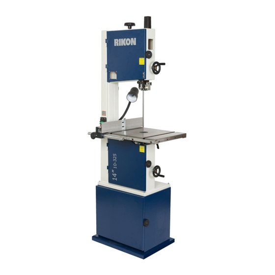
For RIKON 14" Bandsaws 10-324 & 10-325
* PATENT PENDING
Installation & User Manual
Record the date of purchase in your manual for future reference.
Date of purchase: _________________________
For technical support or parts questions, email techsupport@rikontools.com or call toll free at (877)884-5167
www.rikontools.com
10-900M1a
Advertisement
Table of Contents

Subscribe to Our Youtube Channel
Summary of Contents for Rikon Power Tools 10-324
- Page 1 10-900 Tool-less Blade Guide System Retrofit Kit For RIKON 14” Bandsaws 10-324 & 10-325 * PATENT PENDING Installation & User Manual Record the date of purchase in your manual for future reference. Date of purchase: _________________________ For technical support or parts questions, email techsupport@rikontools.com or call toll free at (877)884-5167 www.rikontools.com...
- Page 2 TABLE OF CONTENTS Safety Instructions ......................2 Contents of Package .....................2 & 3 Assembly ....................3 - 6 Adjustments......................7 - 9 Maintenance ......................9 Parts Diagrams & Parts Lists ..................10 - 11 SAFETY INSTRUCTIONS 1. The machine must not be plugged in and the power switch must be in the OFF position until assembly is complete.
-
Page 3: Contents Of Package
CONTENTS OF PACKAGE TABLE OF LOOSE PARTS Tools and Tool Holder: A. Upper Blade Guide Assembly B. Lower Blade Guide Assembly C. Upper Blade Guard D. Scale for Blade Guard Additional Tools Required - not supplied #2 Phillips Screwdriver 10mm Wrench or an Adjustable Wrench NOTE: Parts referenced throughout the instructions refer to the key numbers of the Parts Diagrams and Parts Lists on... -
Page 4: Assembly
ASSEMBLY INSTALLING THE UPPER BLADE GUIDES - continued 3. Once the blade guard is unscrewed, remove the THE MACHINE MUST NOT BE guard from the saw frame. This original guard will not PLUGGED IN AND THE POWER SWITCH MUST BE IN THE be used with the new tool-less blade guides in the Kit. -
Page 5: Assembly
ASSEMBLY INSTALLING THE LOWER BLADE GUIDES Remove the lower drive wheel from the machine. 1. Loosen the drive belt tension and remove the drive belt from the lower wheel’s rear pulley step. 2. Remove the center Bolt and Washer that secure the lower wheel to the motor’s drive shaft. 3. -
Page 6: Adjustments
Changes and improvements may be made at any time, with no obligation on the part FOR INFORMATION ON of RIKON Power Tools, Inc. to modify previously delivered MACHINES, MANUALS, units. Reasonable care has been taken to ensure that the... -
Page 7: Adjustments
ADJUSTMENTS ADJUSTING THE BLADE GUIDES The Tool-less Blade Guide System features quick- adjusting, spring loaded, ball bearing blade guides for fast and easy setting to the blades. With the bandsaw blade properly centered on the drive wheels, the guide bearings can then be set. NOTE: The following photos are representative of the Tool-less Guide System and may not specifically match your machine. -
Page 8: Locking Handle
ADJUSTMENTS Adjusting the Lower Guides - continued: 2. The guides should be approximately 1/16” behind the gullets of the saw blade. If they need to be moved, loosen the Lever Handle (Fig. 11, A), located to the left of the Lower Guide Block (B), and move this block that holds the guides so that the guides are properly positioned behind the blade gullets. -
Page 9: Set Screw
ADJUSTMENTS ADJUSTING THE BLADE GUARD - continued THE MACHINE MUST NOT BE PLUGGED IN AND THE POWER SWITCH MUST BE IN THE 2. When the guide bearings are in proper position, OFF POSITION UNTIL ALL ADJUSTMENTS ARE COMPLETE. re-tighten the guidepost lock knob. NOTE: The guide post is pre-set at the factory to aligned vertical with the bandsaw blade. - Page 10 PARTS DIAGRAM 30 31...
- Page 11 PARTS LIST DESCRIPTION PART NO. KEY NO. QTY. Blade guard 1-JMBS1404051000-114X Hex socket cap screw M5x12 1-M5X12GB70D1B Flat washer 1-WSH5GB97D1B Locking handle 1-JMBS1403050004-001S Window 1-JMBS1404050001 Allen flat end set screws M8x10 1-M8X10GB77B Locking handle 1-JMBS1801052002-001S Spacer 1-JMBS1403014007 Spring 1-JMBS1403014005 Upper guide 1-JMBS1401051001 Locking handle 1-JMBS1403014006-001S...
- Page 12 10-900 Tool-less Blade Guide System * Retrofit Kit For RIKON 14” Bandsaws 10-324 & 10-325 For more information: * PATENT PENDING 16 Progress Road Billerica, MA 01821 877-884-5167 / 978-528-5380 techsupport@rikontools.com www.rikontools.com 10-900M1a...
- Page 13 RIKON #10-900 TOOL-LESS BLADE GUIDE SYSTEM RETROFIT KIT INSTRUCTIONS ADDENDUM Addendum Notes to page 5 of the #10-900 Instructions – INSTALLING THE LOWER BLADE GUIDES Reference Instruction’s Step 7 and Figures 4 & 5. On older models of the 10-325 Bandsaws, the pre-bored mounting hole in the frame (Figure 4) may not be an oval shape to accept both connecting Hex Socket Cap Screw and Alignment Pin that are on the underside of the Retrofit Guide’s Connecting Plate (Parts List #26).


Need help?
Do you have a question about the 10-324 and is the answer not in the manual?
Questions and answers