Table of Contents
Advertisement
Quick Links
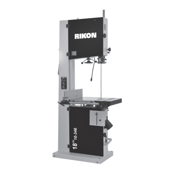
10-346
18" Professional Bandsaw
4001824
Operator's Manual
Record the serial number and date of purchase in your manual for future reference.
Serial Number: _________________________
Date of purchase: _________________________
For technical support or parts questions, email techsupport@rikontools.com or call toll free at (877)884-5167
www.rikontools.com
10-346M1
Advertisement
Table of Contents

Related Manuals for Rikon Power Tools 18” Professional Bandsaw


Summary of Contents for Rikon Power Tools 18” Professional Bandsaw
- Page 1 10-346 18” Professional Bandsaw 4001824 Operator’s Manual Record the serial number and date of purchase in your manual for future reference. Serial Number: _________________________ Date of purchase: _________________________ For technical support or parts questions, email techsupport@rikontools.com or call toll free at (877)884-5167 www.rikontools.com 10-346M1...
-
Page 2: Table Of Contents
TABLE OF CONTENTS Specifications........................2 Safety Instructions ......................3 - 6 Getting To Know Your Machine ..................7 Contents of Package ....................8 - 9 Assembly .........................10 - 11 Adjustments.......................11 - 15 Operation ........................16 - 17 Maintenance ........................18 Wiring Diagram ........................18 How To Guide for all Band Saw Blades ..................19 Troubleshooting ......................20 - 23 Parts Explosions &... -
Page 3: Safety Instructions
SAFETY INSTRUCTIONS IMPORTANT! Safety is the single most important consideration in the operation of this equipment. The following instructions must be followed at all times. Failure to follow all instructions listed below may result in electric shock, fire, and/or serious personal injury. There are certain applications for which this tool was designed. - Page 4 SAFETY INSTRUCTIONS 12. KEEP PROTECTIVE GUARDS IN PLACE AND IN 25. ALWAYS WEAR A DUST MASK TO PREVENT WORKING ORDER. INHALING DANGEROUS DUST OR AIRBORNE PARTICLES, including wood dust, crystalline silica dust 13. AVOID ACCIDENTAL STARTING. Make sure that the and asbestos dust.
-
Page 5: Electrical Safety
SAFETY INSTRUCTIONS ELECTRICAL SAFETY EXTENSION CORDS Keep the extension cord clear of the working area. Position the cord so that it will not get THIS TOOL REQUIRES THE INSTALLATION OF caught on lumber, tools or other obstructions while A 220V PLUG (NOT INCLUDED), AND MUST BE you are working with a power tool. -
Page 6: Save These Instructions
Changes and improvements may be made at any time, with no obligation on the part of Rikon Power Tools, Inc. to modify previously delivered units. Reasonable care has been taken to ensure that the information in this manual is correct, to provide you with the guidelines... -
Page 7: Getting To Know Your Machine
GETTING TO KNOW YOUR MACHINE A. Hoist Ring L. Lower Door Blade Guard B. Tension Indicator Window M. 4” Dust Ports C. Blade Tension Hand Wheel N. Foot Brake D. Switch O. Blade Tracking Knob E. Rip Fence P. Quick Release Lever F. -
Page 8: Contents Of Package
CONTENTS OF PACKAGE Model 10-346 18” Professional Bandsaw is shipped complete in one crate. Unpacking and Checking Contents a. Separate all “loose parts” from packaging materials and check each item with “Table of Loose Parts” to make sure all items are accounted for, before discarding any packaging material. b. - Page 9 CONTENTS OF PACKAGE LIST OF LOOSE PARTS Table Assembly: A. Table B. Rip Fence Rail Rip Fence Assembly: A. Rip Fence B. Rip Fence Carrier C. Re-saw Bar Bandsaw Accessories: A. Hoist Ring* B. Hex Screw & Nut for Hanging Push Stick* C.
-
Page 10: Assembly
ASSEMBLY INSTALLING THE WORK TABLE The Work Table is extremely heavy. It may require two other individuals to assist with the installation. NOTE: The upper and lower bandwheel doors must remain closed during table installation. The guide shaft (A-Fig.1) and table locking hardware (B-Fig.1) were installed on the lower trunnion (C-Fig.1) Figure 1 during saw assembly. - Page 11 ASSEMBLY / ADJUSTMENTS INSTALLING THE 4” DUST PORT The 4” dust port under the table is installed on the frame above the lower door knob. Locate four 4mm pan head screws and four 4mm flat washers from the hardware pack. Using a Phillips-head screw driver install the screws through the dust port flange into pre-threaded holes in the frame.
-
Page 12: Adjustments
ADJUSTMENTS TILTING THE TABLE Loosen the locking handle (A-Fig.9) on the table trunnion. Install the Table Tilting Wrench (B-Fig.9) onto the Gear Shaft (C-Fig.9). Turn the Table Tilting Wrench to adjust the table to the desired angle. Use the angle indicator scale on the trunnion bracket to find the desired angle. - Page 13 ADJUSTMENTS Always tension the blade with the quick release lever in the “On” position. Failure to do so could result in lack of blade tension or tension failure. BLADE TENSION INDICATOR ADJUSTMENT The Blade Tension Indicator arrow should be checked and adjusted the first time the saw is set up and run, and whenever a new blade is installed.
- Page 14 ADJUSTMENTS Continued from Page 13 f) Re-tension the new blade by moving the quick release lever (Fig.15) left to right and check the blade tracking. With your hand, slowly spin the upper wheel clockwise three times. The blade should run in the center of both wheels. Refer to “Tracking the Saw Blade”...
- Page 15 ADJUSTMENTS When the correct adjustment is reached, lock the guides in position by re-tightening the lock knob (B-Fig.20). Adjust the thrust guide to be just clear of the back of the blade by unlocking the wing nut (C-Fig.20), and turning adjusting knob on rear of the trunnion. Finally, re-tighten the wing nut (C-Fig.20).
-
Page 16: Operation
OPERATION BASIC OPERATION The blade cuts on a continuous down-stroke. Never start the saw with the workpiece in contact with the saw blade. With both hands, firmly hold the workpiece down on the table, and feed it slowly towards the blade, putting only light pressure on it, and keeping your hands away from the blade. - Page 17 OPERATION RE-SAWING A re-saw guide bar is supplied to help correct any blade wandering during certain re-sawing operations. For re-sawing, attach the re-saw bar to the slot on the fence. Position the re-saw bar so that it is aligned with the front of the blade.
-
Page 18: Maintenance
MAINTENANCE BEFORE CLEANING OR CARRYING OUT MAINTENANCE WORK, DISCONNECT THE MACHINE FROM THE POWER SOURCE (WALL SOCKET). NEVER USE WATER OR OTHER LIQUIDS TO CLEAN THE MACHINE. USE A BENCH BRUSH. DO NOT USE COMPRESSED AIR NEAR BEARINGS. REGULAR MAINTENANCE OF THE MACHINE WILL PREVENT UNNECESSARY PROBLEMS. -
Page 20: Troubleshooting
TROUBLESHOOTING FOR YOUR OWN SAFETY, ALWAYS TURN OFF AND UNPLUG THE MACHINE BEFORE CARRYING OUT ANY TROUBLESHOOTING. TROUBLE PROBABLE CAUSE REMEDY The machine does not 1. No power supply. Check the cable for breakage. work when switched on. 2. Defective switch. Contact your local dealer for repair. - Page 21 TROUBLESHOOTING CHANGING THE MOTOR DRIVE BELT (Refer to “Frame Assembly” parts diagram on page 24 and “Wheel Assembly” parts diagram on page Before changing the belt, make sure that the bandsaw is unplugged from the power source. Release the saw blade tension from the drive belt by turning the quick release blade tension lever. From the rear of the machine, loosen the two Hex Nuts (Part #54) that secure the motor to the frame.
- Page 22 TROUBLESHOOTING LOWER WHEEL ADJUSTMENTS The following instructions will correct common blade issues related to the lower wheel’s alignment in relation to the upper wheel. These adjustments will correct the blade position on the lower wheel and blade oscillation (wobble). These are critical adjustments which affect the performance and accuracy of the bandsaw.
- Page 23 TROUBLESHOOTING If a blade is tracking on the rear of the lower wheel, away from the door, follow these steps: De-tension the saw blade. Loosen 9 o’clock shaft bolt to take pressure off the shaft. Loosen 6 o’clock shaft bolt one half rotation. Tighten the 12 o’clock shaft bolt until the shaft touches the 6 o’clock adjusting bolt.
-
Page 24: Parts Explosions & Parts Lists
PARTS DIAGRAM FRAME ASSEMBLY NOTE: Please reference the Manufacturer’s Part Number when calling for Replacement Parts. For Parts under Warranty, the serial number of your machine is required. - Page 25 PARTS LIST FRAME ASSEMBLY KEY NO. DESCRIPTION QTY MFG. PART NO. KEY NO. DESCRIPTION QTY MFG. PART NO. Ring Bolt P10-346-1 Hex Nut P10-346-62 Pan Head Screw P10-346-2 Big Washer P10-346-63 Tool Holder P10-346-3 P10-346-64 Frame P10-346-4 Braking Bracket P10-346-65 Pan Head Screw P10-346-5 Spring...
- Page 26 PARTS DIAGRAM WHEEL ASSEMBLY...
- Page 27 PARTS LIST WHEEL ASSEMBLY KEY NO. DESCRIPTION MFG. PART NO. Hexagon Socket Cap Screw P10-346-123 Washer P10-346-124 Retaining Ring P10-346-125 Deep Groove Ball Bearing P10-346-126 Upper Wheel P10-346-127 Tube P10-346-128 Tire P10-346-129 Blade P10-346-130 Lower Wheel P10-346-131 NOTE: Please reference the Manufacturer’s Part Number when calling for Replacement Parts. For Parts under Warranty, the serial number of your machine is required.
- Page 28 PARTS DIAGRAM TABLE ASSEMBLY...
- Page 29 PARTS LIST TABLE ASSEMBLY KEY NO. DESCRIPTION QTY MFG. PART NO. Hex Nut P10-346-132 Hex Bolt P10-346-133 Lock Nut P10-346-134 Guide Shaft P10-346-135 Flat Washer P10-346-136 Gear Shaft P10-346-137 Lock Handle P10-346-138 Flat Washer P10-346-139 Rivet P10-346-140 Angle Label P10-346-141 Flat Washer P10-346-142 Indicator...
- Page 30 PARTS DIAGRAM BLADE TENSION & TRACKING...
- Page 31 PARTS LIST BLADE TENSIONING & TRACKING KEY NO. DESCRIPTION MFG. PART NO. Cap Nut P10-346-166 Spring Washer P10-346-167 Flat Washer P10-346-168 Hex Nut P10-346-169 Spring Washer P10-346-170 Lock Nut P10-346-171 Flat Washer P10-346-172 Bolt P10-346-173 Threaded Rod P10-346-174 Set Screw P10-346-175 Sliding Block P10-346-176...
- Page 32 PARTS DIAGRAM GUIDE POST ASSEMBLY NOTE: Please reference the Manufacturer’s Part Number when calling for Replacement Parts. For Parts under Warranty, the serial number of your machine is required.
- Page 33 PARTS LIST GUIDE POST ASSEMBLY KEY NO. DESCRIPTION MFG. PART NO. Retaining Ring P10-346-200 Rack P10-346-201 Blade Guard P10-346-202 P10-346-203 Flat Washer P10-346-204 Clear Window P10-346-205 Pan Head Screw P10-346-206 P10-346-207 Hexagon Socket Cap Screw P10-346-208 Flat Washer P10-346-209 Upper Guide Base P10-346-210 Hexagon Socket Cap Screw P10-346-211...
- Page 34 PARTS DIAGRAM FENCE ASSEMBLY PARTS LIST FENCE ASSEMBLY KEY NO. DESCRIPTION MFG. PART NO. Plate P10-346-213 Fence Carrier P10-346-214 Handle P10-346-215 Washer P10-346-216 Hexagon Socket Cap Screw P10-346-217 Fence Rail P10-346-218 Joint Lever P10-346-219 P10-346-220 Flat Washer P10-346-221 Hex Nut P10-346-222 Stop Lever P10-346-223...
-
Page 35: Warranty
WARRANTY WARRANTY... - Page 36 10-346 For more information: 16 Progress Rd Billerica, MA 01821 877-884-5167 / 978-528-5380 techsupport@rikontools.com www.rikontools.com 10-346M1...
Need help?
Do you have a question about the 18” Professional Bandsaw and is the answer not in the manual?
Questions and answers