Table of Contents
Advertisement
Quick Links
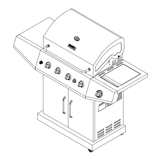
ASSEMBLY & OPERATING INSTRUCTIONS
Liquid Propane Gas Grill
!
WARNING:
Read this Owner's manual carefully and be
sure your gas grill is properly assembled,
installed and maintained. Failure to follow these
instructions could result in serious injury and/or
property damage. This gas grill is intended for
outdoor use only and is not intended to be
installed in or on recreational vehicles or boats.
Note to Installer
Leave this Owner's Manual with the customer
after delivery and/or installation.
400
300
500
200
600
100
700
800
Nexgrill Industries, INC.
5270 Edison Ave. Chino, CA 91710
Note to Consumer
Leave this Owner's Manual in a convenient
place for future reference.
Customer Service Helpline:
For parts ordering, call:
1-800-913-8999
MFG No.: 720-0670D
Please make sure the cylinder valve
connection device shall properly and safely
mate with the connection device attached to
the inlet of the pressure regulator.
• Parts
• Assembly
• Safety Rules
• Use and Care
• Troubleshooting
19000378A0
Advertisement
Table of Contents

Related Manuals for Nexgrill 720-0670D


Summary of Contents for Nexgrill 720-0670D
- Page 1 For parts ordering, call: outdoor use only and is not intended to be 1-800-913-8999 installed in or on recreational vehicles or boats. MFG No.: 720-0670D Note to Installer Leave this Owner’s Manual with the customer Please make sure the cylinder valve after delivery and/or installation.
-
Page 2: Table Of Contents
Table of Contents Safety Precautions WARNING Warranty------------------------------------------------2 Combustion by products produced when using Safety Precautions--------------------------------2~4 this product contain chemicals known to the Hardware List------------------------------------------5 State of California to cause cancer, birth defects, Parts Diagram -----------------------------------------6 or other reproductive harm. Parts List------------------------------------------------7 Assembly Instructions---------------------------8~12 WARNING Lighting Instructions----------------------------12~14... -
Page 3: Safety Precautions
Safety Precautions A tank of approximately 12 inches in diameter by 18- • Have your LP gas tank filled by a reputable 1/2 inches high is the maximum size LP gas tank to propane gas dealer and visually inspected and re- use. - Page 4 WARNING Burner Flame Check A strong gas smell, or the hissing sound of gas indicates a serious problem with your gas grill or the LP gas tank. Failure to immediately follow the steps listed below could result in a fire or explosion that could cause serious bodily injury, death, or property damage.
- Page 5 Contents for Hardware Pack The following table illustrates a breakdown of the hardware pack. It highlights what components are used in the various stages of assembly. Item Description Specification Quantity Phillips Head Screw 1/4"x 15mm 35 pcs Phillips Head Screw 5/32"x 10mm 22 pcs Flat Head Screw...
-
Page 6: Parts Diagram
Model 720-0670D Parts Diagram... -
Page 7: Parts List
Model 720-0670D Parts List KEY# DESCRIPTION Q’TY KEY# DESCRIPTION Q’TY Main Lid Front Door, Right Warming Rack Lighting Rod Main Lid Screw Door iron piece Temperature Gauge Back Panel, bottom Hood Buffer A Back Panel, top Logo Diagonal Bar Barrier... -
Page 8: Assembly Instructions
Assembly Instructions Figure 1 CAUTION: While it is possible for one person to assemble this grill, obtain assistance from another person when handling some of the larger, heavier pieces 1. Open lid of shipping carton and remove top sheet of cardboard. Lay cardboard sheet on floor and use as a work surface to protect floor and grill parts from scratches. - Page 9 Figure 7 5. Attach the diagonal bar barrier to back & bottom panel using (2)5/32*10mm Phillips head screws with (2) 5/32 lock washers.(Fig.5) 6. Attach door handles to doors by using (4) 5/32 x 10mm Phillips head screws. (Fig. 6) 7.
- Page 10 Figure 12 Installing Side Burner Shelf & Side Shelf 4pcs: 1/4 X 15mm 1. Remove (2) preinstalled 1/4 x 15mm Phillips head screws from left side of grill head as shown. Do not remove screws in fully; leave ¼ extended for shelf assembly.
- Page 11 Installing Battery Figure 16 1.Unscrew the ignition battery cap. (Found at far left of control panel). 50 0 60 0 10 0 2.Install battery into ignition box with positive terminal facing outward. 3.Replace the ignition battery cap after the battery has been installed.
- Page 12 Connecting LP Gas Tank to LP Grill Figure 21 1.Remove the screw on tank bolt & take off the washer. Insert the tank bolt from rear of the grill and Regulator Connection reinstall the washer & screw set. From Rear of the cart, place foot ring of 20 lb tank into the hole in bottom panel.
-
Page 13: Lighting Instructions
Checking for LP gas leaks Never test for leaks with a flame. Prior to first use, at the beginning of each season, or every time your LP gas tank is changed, you must check for gas leaks. 7. To light additional burners, push and turn burner knob (s) 1. - Page 14 If Grill Still Fails To Light WARNING 1. Check gas supply and connections for leaks. Check Never lean over the grill cooking area while that all wire connections are secure. lighting your gas grill. Keep your face and body a safe distance (at least 18 inches) from the 2.
-
Page 15: Cleaning And Maintenance
Cleaning and Maintenance Cleaning Exterior Stainless Steel Surfaces To ensure a proper working unit the following proper care and maintenance is suggested. •Weathering and extreme heat can cause exterior stainless steel surfaces to turn tan in color. Machine Cleaning Cooking Grids oils used in manufacturing process of stainless steel We suggest you wash your cooking grids in a mild soap can also cause this tanning color. -
Page 16: Troubleshooting
3. Inspect each burner for damage (cracks or holes) Regardless of which burner cleaning procedure you and if such damage is found, order and install a new use, we recommend you also complete the following burner. After installation check to ensure that gas steps to help prolong burner life. -
Page 17: Cooking Instruction
Cooking Instructions Indirect Cooking To cook indirectly, the food should be placed on the left or right side of your grill with the burner lit WARNING on the opposite side. Indirect cooking must be Do not leave the grill unattended. done with the Lid down. - Page 18 Grill Cooking Chart FOOD Weight or thickness Temperature Time Special instructions and tips Slice or chop vegetables and dot with butter or Vegetables Medium 8 to 20 minutes margarine. Wrap tightly in heavy duty foil. Grill turning occassionally. Wrap individually in heavy duty foil. Cook Potatoes Whole Medium...
Need help?
Do you have a question about the 720-0670D and is the answer not in the manual?
Questions and answers