Table of Contents
Advertisement
Figure 325
CSA International
Project 2070363
2 of 31
WARNING
To reduce the risk of fire, burn hazard or
other injury, read the Care and Use
Manual carefully and completely before
using your grill.
Example only: SERIAL # ________ MFG. DATE ________ PURCHASE DATE: _________
Questions, problems, missing parts? Before returning to your retailer, call our customer
service department at 1-877-323-5263, 8 a.m. - 6 p.m., PST, Monday - Friday, 8 a.m. – 12 p.m.
Saturday.
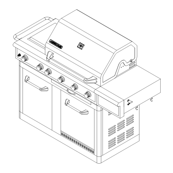
ITEM / ARTICLE / ARTICULO # 296469
STAINLESS STEEL GAS GRILL
MODEL / MODÈLE / MODELO # 720-0665
WARNING
FOR OUTDOOR USE ONLY
WARNING
This grill is not intended to be
installed in or on recreational
vehicles and/or boats.
®
Advertisement
Table of Contents

Related Manuals for Nexgrill 296469


Summary of Contents for Nexgrill 296469
- Page 1 Figure 325 CSA International Project 2070363 2 of 31 ITEM / ARTICLE / ARTICULO # 296469 STAINLESS STEEL GAS GRILL MODEL / MODÈLE / MODELO # 720-0665 WARNING WARNING To reduce the risk of fire, burn hazard or FOR OUTDOOR USE ONLY other injury, read the Care and Use ®...
-
Page 2: Table Of Contents
Figure 325 CSA International Project 2070363 3 of 31 TABLE OF CONTENTS Safety Information….…………………………………………………..………………...……..….2 Package Contents List………………………………………………………………………..……..7 Preparation……………….…………………. ……………………….…………….………………..7 Assembly Instructions…………………………………………………………….…..……..………7 Installation Instructions……………………………………………………………..…….……...11 Operation Instructions…….…………………………………………………….…..…..……….…14 Gas Conversion from LP to NG…………………………………………………………………...17 Refrigerator Safe Guide……………………………………………………………………………22 Care and Maintenance……………………………………………………………………………..24 Troubleshooting…………………………………………………………………..……….……..…26 Warranty………………………………….…………………………………………..………..…….28 Replacement Parts List………………….…...……………………………………..…….……….29 SAFETY INFORMATION RECOGNIZED SAFETY SYMBOLS, WORDS AND LABELS DANGER... - Page 3 Figure 325 CSA International Project 2070363 4 of 31 WARNING 1. The grill and its individual shut-off valve must be disconnected from the gas supply piping system during any pressure testing of that system at test pressure in excess of 1/2 psi. (3.5 kpa). 2.
- Page 4 Figure 325 CSA International Project 2070363 5 of 31 BEFORE LIGHTING Inspect the gas supply hoses prior to turning on the gas. If there is evidence of cuts, wear, or abrasion, it must be replaced prior to use. Only the pressure regulator and hose assembly supplied with the unit should be used. Never substitute regulators for those supplied with the grill.
- Page 5 Figure 325 CSA International Project 2070363 6 of 31 Children should not be left alone or unattended in an area where the grill is being used. Do not allow children to sit, stand or play on or around the grill at any time. Do not store items of interest to children around or below the grill or cart.
- Page 6 Figure 325 CSA International Project 2070363 7 of 31 Do not use briquettes of any kind in the grill. 720-0665 liquid propane gas grill is designed for optimum performance without the use of briquettes. Do not place briquettes on the flame tamers as this will block the ventilation to the grill burners. Adding briquettes can damage ignition components, thus voiding the warranty.
-
Page 7: Package Contents List
Figure 325 CSA International Project 2070363 8 of 31 PACKAGE CONTENTS LIST 1. Grill Body Assembly-----1pc. 12. Right Side Shelf----------1pc. 3. Left Side Shelf Handle-1pc. 4. Hook-------2pcs. .5. Bottle Opener-------1pcs. PREPARATION Before beginning assembly, installation or operation of product, make sure all parts are present. Compare parts with package contents list and diagram above. - Page 8 Figure 325 CSA International Project 2070363 9 of 31 2. Right side Shelf Assembly Fig. 3 (1) Remove one screw (B) 5/32-in. x 10mm as shown in Fig. 3 and three (A) 1/4-in. x 15mm truss head screws that have been pre-placed into the right side panel as shown fig.
- Page 9 Figure 325 CSA International Project 2070363 10 of 31 Fig. 6 Fig. 7 3. Battery Installation Unscrew the ignition button housing (A); insert the battery from pack D into the housing with the positive terminal (+) facing outward (B). Replace the ignition button housing after the battery has been installed as shown in Fig.
- Page 10 Figure 325 CSA International Project 2070363 11 of 31 Fig. 9 5. Hooks Installation Fig. 10 Align the holes in the bottom of right side panel of side shelf, and hang the hooks. Fig. 11 6. Tank Tray Slide Out Bracket Before pulling the tank tray slide, should rotate the bracket according to the A arrowhead as shown in Fig.
-
Page 11: Installation Instructions
Figure 325 CSA International Project 2070363 12 of 31 7. Liquid Propane Tank Installation Fig. 12 (1)According to step 6, pull the tank tray, and place the liquid propane tank into the tank tray and tighten the retention screw to fix the tank as shown in Fig. 12. (2) Push the tank tray to the end, and then lock the tank tray slide as shown in Fig. - Page 12 Figure 325 CSA International Project 2070363 13 of 31 LIQUID PROPANE CYLINDER REQUIREMENTS (20-lb Cylinder) A dented or rusty Liquid Propane cylinder may be hazardous and should be checked by your supplier. Never use a cylinder with a damaged valve. The Liquid Propane cylinder must be constructed and marked in accordance with the specifications for Liquid Propane cylinders by the United States Department of Transportation (DOT) or the National Standard of Canada, CAN/CSA-B339, Cylinders, Spheres and Tubes for Transportation of Dangerous Goods Commission.
- Page 13 Figure 325 CSA International Project 2070363 14 of 31 LEAK TESTING GENERAL Although gas connections on the grill are leak tested prior to shipment, a complete leak test must be performed at the installation site. Before each use, check all gas connections for leaks using the procedures listed below. If the smell of gas is detected at any time, you should immediately check the entire system for leaks.
-
Page 14: Operation Instructions
Figure 325 CSA International Project 2070363 15 of 31 WARNING 1. The grill and its individual shutoff valve must be disconnected from the gas supply piping system during any pressure testing of that system at test pressure in excess of 1/2-in. psi. (3.5kpa). 2. - Page 15 Figure 325 CSA International Project 2070363 16 of 31 Using the Rotisserie Burner Your grill is capable of performing back burner rotisserie cooking. Light the rear burner as described in the Lighting Instructions on page 15. Once lit, the rotisserie burner will reach cooking temperature in about 1 minute.
- Page 16 Figure 325 CSA International Project 2070363 17 of 31 Fig. 15 TO LIGHT THE ROTISSERIE BURNER 1. Open the lid, push and turn rear burner knob slowly to “IGNITE/ON” , keep pushing until the burner is lit. Once it is lit, continue to press and hold for another 15 seconds to ensure the burner stay lit.
-
Page 17: Gas Conversion From Lp To Ng
This grill is certified for use with either Liquid Propane (LP Gas) or Natural Gas and comes complete with the necessary parts to convert the grill for use with Natural Gas hose and regulator sold separately. The Nexgrill patented Conversion Valves allows the use of Natural Gas without replacing the burners or entire valve system. - Page 18 1.07 13,000 1.84 13,000 Natural Gas Conversion for Item#296469/Model# 720-0665 Warning: Make sure all grill components are completely cool and gas supply is turned off and removed from grill prior to performing the conversion. NG Hose and Regulator Conversion Tools required:...
- Page 19 Figure 325 CSA International Project 2070363 20 of 31 3. Screw the Regulator on the right side panel from inside to outside. 4. Install the NG regulator hose to the manifold and secure using a wrench. Main Tube Burner Conversion Tools Required Phillips Head Screwdriver (+) 6mm Nut Driver...
- Page 20 Figure 325 CSA International Project 2070363 21 of 31 2. Locate and remove the LP orifice at the end of each valve with an nut driver. The main burner NG orifices are located behind the LP orifices, so no additional orifices need to be installed. CAUTION: The NG orifice is easily loosed or even removed together with the LP orifice when the LP orifice is being unscrewed.
- Page 21 Figure 325 CSA International Project 2070363 22 of 31 2. Take out the searing side burner from the firebox. Locate orifice on end of valve and remove by turning counterclockwise with a 6mm Nut Driver 3. Insert NG orifice with a 6mm Nut Driver, then secure and turning clockwise in tightly. Replace the searing side burner, searing side burner and igniter wire back.
-
Page 22: Refrigerator Safe Guide
Figure 325 CSA International Project 2070363 23 of 31 3. Take out the LP orifice, and place the NG orifice accordingly. After the orifice is placed, put the cover of the rear burner back to its original location. REFRIGERATOR SAFE GUIDE IMPORTANT: READ THE FOLLOWING PRIOR TO CONNECTING POWER AND USE To reduce the risk of fire, electrical shock or injury when using this unit, follow basic precaution, including the following. - Page 23 Figure 325 CSA International Project 2070363 24 of 31 INSTALLATION INSTRUCTIONS Before Using Your Unit • Remove the exterior and interior packing. • Before connecting the unit to the power source, let it stand upright for approximately 2 hours. This will reduce the possibility of a malfunction in the cooling system from handling during transportation.
-
Page 24: Care And Maintenance
Figure 325 CSA International Project 2070363 25 of 31 Refrigerator Technical Data ITEM DATA Voltage (V) Frequency (Hz) Current (A) 1.38 Input Wattage (W) Consumptions (KW.h/24h) Volume (cu.ft.) Dimension (mm) 442*470*500 Refrigerant R134a High Pressure (psig) Low Pressure (psig) Net Weight (kg) Insulation CARE AND MAINTENANCE Stainless Steel... - Page 25 Figure 325 CSA International Project 2070363 26 of 31 To remove the main burners for cleaning: Fig. 17 1. Locate the burner screw at the rear of the firebox. 2. Remove the screw and lift the burner out of the firebox. To clean the grill burners: 1.
-
Page 26: Troubleshooting
Figure 325 CSA International Project 2070363 27 of 31 TROUBLESHOOTING Please refer to the following Troubleshooting Guide if you have any problems lighting or operating your grill. Many solutions given here can make your grilling experience safer and more enjoyable. Problems Possible Solutions Grill will not light... - Page 27 Figure 325 CSA International Project 2070363 28 of 31 Problems Possible Solutions Burner blows out 1. Check for any burner defects. 2. Check for proper burner installation. 3. Make certain the fuel mixture is not too lean. 4. Make sure the gas supply is sufficient. 5.
-
Page 28: Warranty
LIMITED WARRANTY (Model # 720-0665) Nexgrill warrants to the original consumer-purchaser only that this product (Model #720-0665) shall be free from defects in workmanship and materials after correct assembly and under normal and reasonable home use for the periods indicated below beginning on the date of purchase. The manufacturer reserves the right to require photographic evidence of damage, or that defective parts be returned, postage and or freight pre-paid by the consumer, for review and examination. -
Page 29: Replacement Parts List
Figure 325 CSA International Project 2070363 30 of 31 REPLACEMENT PARTS LIST For replacement parts, call our customer service department at 1-877-323-5263, 8 a.m. – 6 p.m., PST, Monday – Friday and 8 a.m. – 12 p.m. PST, Saturday. Warranty Warranty REF# DESCRIPTION... - Page 30 Figure 325 CSA International Project 2070363 31 of 31 Printed in China...
Need help?
Do you have a question about the 296469 and is the answer not in the manual?
Questions and answers