Table of Contents
Advertisement
Figure 338
CSA International
Project 2075516
2 of 38
WARNING
To reduce the risk of fire, burn hazard or
other injury, read the Care and Use
Manual carefully and completely before
using your grill.
Example only: SERIAL # ________ MFG. DATE ________ PURCHASE DATE: _________
Questions, problems, missing parts? Before returning to your retailer, call our customer
service department at 1-877-323-5263, 8 a.m. - 6 p.m., PST, Monday - Friday, 8 a.m. – 12 p.m.
Saturday.
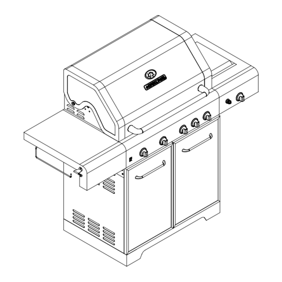
Stainless Steel LP GAS GRILL
WARNING
FOR OUTDOOR USE ONLY
WARNING
This grill is not intended to be
installed in or on recreational
vehicles and/or boats.
ITEM / ARTICLE / ARTICULO # 296459
MODEL / MODÈLE / MODELO # 720-0649
®
Advertisement
Table of Contents

Related Manuals for Nexgrill 720-0649


Summary of Contents for Nexgrill 720-0649
- Page 1 CSA International Project 2075516 2 of 38 ITEM / ARTICLE / ARTICULO # 296459 STAINLESS STEEL LP GAS GRILL MODEL / MODÈLE / MODELO # 720-0649 WARNING WARNING To reduce the risk of fire, burn hazard or FOR OUTDOOR USE ONLY ®...
-
Page 2: Table Of Contents
Figure 338 CSA International Project 2075516 3 of 38 TABLE OF CONTENTS Safety Information….…………………………………………………..………………...……..….3 Package Contents List………………………………………………………………………..……..7 Preparation……………….…………………. ……………………….…………….………………..8 Assembly Instructions…………………………………………………………….…..……..………8 Installation Instructions……………………………………………………………..…….……...16 Operation Instructions…….…………………………………………………….…..…..……….…19 Gas Conversion From LP to NG…………………………………………………………………..25 Care and Maintenance……………………………………………………………………………..30 Troubleshooting…………………………………………………………………..……….……..…32 Warranty………………………………….…………………………………………..………..…….34 Replacement Parts List………………….…...……………………………………..…….……….35 DANGER WARNING If you smell gas: Do not store or use gasoline or other... -
Page 3: Safety Information
Figure 338 CSA International Project 2075516 4 of 38 SAFETY INFORMATION WARNING Do not try lighting this appliance without first reading WARNING the “LIGHTING INSTRUCTIONS” section of this manual. WARNING – Hazards or unsafe practices which COULD result in severe personal injury or death. - Page 4 Figure 338 CSA International Project 2075516 5 of 38 WARNING WARNING Do not leave the grill unattended while cooking. Spiders and insects can nest inside the burners of the grill and disrupt gas flow. Inspect the grill at least twice a year. WARNING Failure to properly place the burner over the orifice could cause a fire to occur behind and beneath the...
- Page 5 Figure 338 CSA International Project 2075516 6 of 38 Do not use indoors. TESTED IN ACCORDANCE WITH ANSI Z21.58 WARNING LATEST STANDARD and CGA 1.6-2007 Do not try lighting this appliance without first STANDARED FOR OUTDOOR COOKING GAS reading the “LIGHTING INSTRUCTIONS” section APPLIANCES.
- Page 6 Figure 338 CSA International Project 2075516 7 of 38 For proper lighting and performance of the burners, keep the burner ports clean. It is necessary to clean them periodically for optimum performance. The burners will only operate in one position and must be mounted correctly for safe operation.
-
Page 7: Package Contents List
Figure 338 CSA International Project 2075516 8 of 38 PACKAGE CONTENTS LIST A. Body Assembly -----------1pc. B. Bottom Panel----------1 pc. C. Door-----------------------2pcs. D. Side Burner Shelf----------1pc. E. Left Side Shelf------------1pc. F. Left Side Panel----------1pc. G. Right Side Panel----------1pc. H. Back Panel---------------1pc. I. -
Page 8: Preparation
Figure 338 CSA International Project 2075516 9 of 38 HARDWARE CONTENTS Pack Description Quantity 5/32-in. x 10-mm Truss Head Screw 26 pcs. 5/32-in. Locking Washer 26 pcs. 1/4-in. x 15-mm Truss Head Screw 47 pcs. 1/4-in. Locking Washer 47 pcs. 5/32-in. - Page 9 Figure 338 CSA International Fig. 3 Project 2075516 10 of 38 3. Back Panel Assembly Remove the back panel from the carton. Position the back panel (H) with the flat side facing outward. Attach the back panel to the bottom panel (B) with three 1/4-in. x 15-mm truss head screws (CC) and three 1/4-in.
- Page 10 Figure 338 CSA International Fig. 6 Project 2075516 11 of 38 5. Spare Liquid Propane Tank Barrier Bar Assembly Attach the barrier bar (I) to the bottom panel (B) and back panel (H) using two 5/32-in. x 10-mm truss head screws (AA) and two 5/32-in.
- Page 11 Figure 338 CSA International Fig. 8 Project 2075516 12 of 38 Attach the firebox assembly (A) to the grill cart using four 1/4-in. x 15-mm truss head screws (CC) and four 1/4-in. locking washers (DD). Note: Two screws and two washers for each side of cart) as shown in fig.
- Page 12 Figure 338 CSA International Project 2075516 Fig 11 13 of 38 Remove the 3 screws that are pre-placed onto side burner shelf (D). Fig. 12 Align the bottom key holes on side burner shelf (D) with two loosened screws, and tighten these 2 screws.
- Page 13 Figure 338 CSA International Project 2075516 14 of 38 9. Left Side Shelf Assembly Repeat steps 8 for the left side shelf. Fig. 14 10. Side Burner Installation Side tube burner Insert the side burner gas valve, which extends from the right side of the main Side burner gas valve manifold, into the side tube burner.
- Page 14 Figure 338 CSA International Project 2075516 Fig 16 15 of 38 11. Igniter Installation Plug the rear burner and searing main burner igniter wires into the slots in the back of the igniter module as shown in Fig. 16. Gas valve (Note: Rotisserie burner igniter and searing main slot burner wire are located under the main fire box...
- Page 15 Figure 338 CSA International Project 2075516 Fig. 19 16 of 38 14. Flame Tamers, Cooking Grids and Warming Rack Installation Place the flame tamers (Q), cooking grids (P) and warming rack (O) into the grill as shown in Fig. 19. Fig.
-
Page 16: Installation Instructions
Figure 338 CSA International Project 2075516 17 of 38 Fig. 22 17. Liquid Propane Hook-Up Attach the regulator to the propane cylinder by turning the regulator handle clockwise as shown in Fig. 22. If the outdoor cooking appliance is not in use, the gas must be turned “OFF”... - Page 17 Figure 338 CSA International Project 2075516 18 of 38 Remove the plastic valve cover from the Liquid Propane cylinder. Make sure the grill gas hoses do not contact the grease pan or grill firebox when the Liquid Propane cylinder is placed into the cart. CONNECTING THE LIQUID PROPANE CYLINDER To connect the Liquid Propane gas supply cylinder: 1.
- Page 18 Figure 338 CSA International Project 2075516 19 of 38 6. Should the gas continue to leak from any of the fittings, turn the gas supply “OFF” and contact customer service at 1-877-323-5263. 7. If there is evidence of excessive abrasion or wear, or the hose is cut, it must be replaced prior to the outdoor cooking gas appliance being put into operation.
- Page 19 Figure 338 CSA International Project 2075516 20 of 38 It is very important to keep your appliance’s clear and away from any combustible materials. Maintain at least 24 inches of clearances from sides and back and do not use under overhead combustible construction.
- Page 20 Figure 338 CSA International Project 2075516 21 of 38 Using the Rear Burner Your grill is capable of performing back burner rotisserie cooking. Light the rear burner as described in the Lighting Instructions on page 20. Once lit, the rear burner will reach cooking temperature in about 1 minute.
- Page 21 Figure 338 CSA International Project 2075516 22 of 38 Fig. 23 Rear Burner IGNITE / HI IGNITE / HI IGNITE / HI IGNITE / ON IGNITE / ON IGNITE / ON Main Burners Searing Main Burner Side Burner For Main burners IGNITE / HI For Searing main burner IGNITE / ON...
-
Page 22: Operation Instructions
Figure 338 CSA International Project 2075516 23 of 38 Searing Main Burner and Rear Burner 1. If you have already attempted to light the searing main burner or Side burner with the igniter, allow 5 minutes for any accumulated gas to dissipate. 2. - Page 23 Figure 338 CSA International Project 2075516 24 of 38 WARNING Keep any electrical supply cord away from any heated surface. Halogen Bulb Replacement 1. Make sure that the grill has cooled before changing the light bulb. 2. Make sure the light’s power switch on the control panel is in the “OFF”...
- Page 24 Figure 338 CSA International Project 2075516 25 of 38 Then loosen but not remove the upper two screws above the light. 7. Pull out the light bulb and replace with a new bulb. Tighten the four screws. Note: Do not touch the halogen bulb with bare hands. 8.
-
Page 25: Gas Conversion From Lp To Ng
Figure 338 CSA International Project 2075516 26 of 38 Gas Conversion From LP to NG WARNING MAKE SURE ALL CONTROL KNOBS & CYLINDER VALVE ARE IN OFF POSITION BEFORE CONVERTING. This grill is portable and configured for use with Liquid Propane (LP Gas), which is delivered to the grill from removable tanks (LP tanks and their use are covered elsewhere in this manual). - Page 26 Figure 338 CSA International Project 2075516 27 of 38 2.Turn all knobs to OFF. Turn off LP gas supply and remove the LP cylinder from the grill cart. Remove the brass adapter of the LP regulator from the manifold with a wrench. 3.Install the NG regulator hose to the manifold and secure using a wrench.
- Page 27 Figure 338 CSA International Project 2075516 28 of 38 1.Remove the rotisserie kit, warming rack, cooking grids, and flame tamers from the firebox. Remove the main tube burners by removing the screw securing the burners near the back wall of the firebox and the screws near the front of the firebox that secure the igniter brackets to the burners.
- Page 28 Figure 338 CSA International Project 2075516 29 of 38 Searing Main Burner Conversion Tools required: Phillips Head Screwdriver (+) 6mm nut driver 1. Loosen the igniter wire screws, searing main burner brace screws, and back two screws securing searing side burners. 2.
- Page 29 Figure 338 CSA International Project 2075516 30 of 38 1. Remove cooking grid from side burner. Remover the two screws securing the side burner pipe, which are underneath the side burner shelf. Then take off the side burner pipe by hand. 2.
-
Page 30: Care And Maintenance
Figure 338 CSA International Project 2075516 31 of 38 1. Remove the cover of the rear burner by unfastening the screws in the firebox. Use another hand to hold the orifice cover to ensure it doesn’t fall Install burner orifice 2. - Page 31 Figure 338 CSA International Project 2075516 32 of 38 Wear a barbeque mitt to protect your hand from heat and steam. Scrub the hot cooking grates by dipping a bristled barbeque brush in tap water. Cleaning will be more difficult if the grill is allowed to cool. Grease Pan The grease pan should be emptied, wiped down and washed after each use with a mild detergent and warm water solution.
-
Page 32: Troubleshooting
Figure 338 CSA International Project 2075516 33 of 38 Flame Characteristics Check for proper burner flame characteristics. Burner flames should be blue and stable with no yellow tips, excessive noise, or lifting as shown in Fig. 26. The following steps should be followed for correcting the flame characteristics: 1. - Page 33 Figure 338 CSA International Project 2075516 34 of 38 Problems Possible Solutions Burner blows out. 1. Check for any burner defects. 2. Check for proper burner installation. 3. Make certain the fuel mixture is not too lean. 4. Make sure the gas supply is sufficient. 5.
-
Page 34: Warranty
LIMITED WARRANTY (Model # 720-0649) The manufacturer warrants to the original consumer-purchaser only that this product (Model #720-0649) shall be free from defects in workmanship and materials after correct assembly and under normal and reasonable home use for the periods indicated below beginning on the date of purchase. The manufacturer reserves the right to require photographic evidence of damage, or that defective parts be returned, postage and/or freight pre-paid by the consumer, for review and examination. -
Page 35: Replacement Parts List
Figure 338 CSA International Project 2075516 36 of 38 REPLACEMENT PARTS LIST For replacement parts, call our customer service department at 1-877-323-5263, 8 a.m. – 6 p.m., PST, Monday – Friday and 8 a.m. – 12 p.m. PST, Saturday. WARRANTY WARRANTY REF# DESCRIPTION REF# DESCRIPTION... - Page 36 Figure 338 CSA International Project 2075516 37 of 38 WARRANTY WARRANTY REF# DESCRIPTION REF# DESCRIPTION COVERAGE COVERAGE Main burner Warming rack Sear main burner Sear main burner igniter wire Flame tamer Cooking grid w/ hole...
- Page 37 Figure 338 CSA International Project 2075516 38 of 38...
Need help?
Do you have a question about the 720-0649 and is the answer not in the manual?
Questions and answers