Table of Contents
Advertisement
Quick Links
Advertisement
Table of Contents

Related Manuals for Digi SkyCloud Z4500 Series


Summary of Contents for Digi SkyCloud Z4500 Series
- Page 1 Digi SkyCloud User Guide...
- Page 2 Information in this document is subject to change without notice and does not represent a commitment on the part of Digi International. Digi provides this document “as is,” without warranty of any kind, expressed or implied, including, but not limited to, the implied warranties of fitness or merchantability for a particular purpose.
-
Page 3: Table Of Contents
Z4550x Industrial Controllers--Wireless Connect Sensor+ M2M Wireless Get started with SkyCloud Step 1: Get Digi SkyCloud registration information from Digi Step 2: Activate the SIM card in your devices Step 3: Assemble and power your devices Step 4: Log into Digi SkyCloud... - Page 4 Define the Device Summary page and display options Configuration overview for a Connect Sensor+ in SkyCloud Interfaces Services Options Configuration overview for a Z45 Controller in SkyCloud Quick Panel page Services Asset Management Admin Facilities Admin Menu buttons Welcome to Digi SkyCloud...
- Page 5 Log in security on the Z45 Controller Configure a locked login message and disable web server access on a Z45 Controller General security configuration for a Z45 Controller Enable HTTP access and allow LAN and WWAN port access on a Z45 Controller Welcome to Digi SkyCloud...
- Page 6 SkyCloud/DDNS Service Select General Configuration SkyCloud Services Configuration SkyCloud Location Services SkyCloud Network Management Services (NMS) Clear System Connection Stats Configure access to SkyCloud Device Profile page Application Parameters Local Interfaces Port forwarding RS232/RS485 Ports RS232/RS485 Options Welcome to Digi SkyCloud...
- Page 7 Modbus client data type mapping Physical Device to Modbus Mapping Summary Virtual Device to Modbus Mapping Summary Register Addressing IP Address and Port Configuration Parameters Configuring with other SCADA software Change max block read length Change the Max Coalesce Gap Welcome to Digi SkyCloud...
- Page 8 Configure internal temperature settings Safety information Assembly safety information Battery safety Safety notices Technical Specifications Maximum power and frequency bands Cell modem transmit (TX) output power Regulatory information FCC certifications and regulatory information Declaration of Conformity (DoC) Welcome to Digi SkyCloud...
- Page 9 Connect the power supply to the RMS Z45 Detach an accessory from the RMS Z45 Detach the antenna cables from the RMS Z45 Disconnect the power supply from the RMS Z45 Detach the RMS Z45 from the DIN rail Welcome to Digi SkyCloud...
-
Page 10: Welcome To Digi Skycloud
Welcome to Digi SkyCloud Digi SkyCloud is a web-based application that brings alarms, reports and control to your web browser. Applicable hardware This manual supports the following hardware: Z4500x Industrial Controllers--Ethernet Description CTK-Z4500A1X Z45 Industrial Controller Ethernet, Automation Lite* CTK-Z4500A2X... -
Page 11: M2M Wireless
Welcome to Digi SkyCloud M2M Wireless M2M Wireless Your Connect Sensor+ has been shipped with a pre-installed SIM card from M2M Wireless (www.m2mwireless.com). M2M Wireless provides cellular service designed specifically for Connect Sensor+, including seamless access to SkyCloud over a secure private network (VPN). -
Page 12: Get Started With Skycloud
Step 1: Get Digi SkyCloud registration information from Digi If you do not already have access to SkyCloud, contact your Digi representative to set up your organization with a user name and password, and to register your device. -
Page 13: Step 3: Assemble And Power Your Devices
2. Click Login. The SkyCloud Log In page displays. 3. Enter your user name and password. User name: This is the user name assigned to you by Digi, and is usually your email address. Password: Enter the password that was assigned to you when you were registered with SkyCloud. -
Page 14: Connect Sensor
5. Click the name at the top of the pop-up. The SkyCloud web UI displays. 6. From the Interfaces section, click Location Source. The System Location Configuration page displays. a. In the Latitude and Longitude fields, enter the latitude and longitude coordinates. b. Click Submit. Welcome to Digi SkyCloud... -
Page 15: Assemble The Connect Sensor+ Hardware
For the initial assembly, you will need these items from the box: Component Description Connect Sensor+ Battery One lithium metal battery. For battery safety information, see Battery safety Battery care and maintenance. In addition, you also need to provide: Component Description Cellular antenna One cellular antenna. Welcome to Digi SkyCloud... -
Page 16: Step 2: Assemble The Connect Sensor
Place the connection end of the antenna onto the metal female SMA connector on the Connect Sensor+. b. Tighten the plastic housing at the connection end of the antenna. 4. Leave the cover open for the next assembly step. NEXT STEP: Proceed to Step 3: Check the cellular connection. Welcome to Digi SkyCloud... -
Page 17: Step 3: Check The Cellular Connection
Wiring the Connect Sensor+ I/O interface. The Connect Sensor+ cover must be open to wire sensors to the Connect Sensor+. If you choose to wire sensors at a later time, you should close the cover, which snaps in place. Welcome to Digi SkyCloud... - Page 18 For details about closing the Connect Sensor+ enclosure, see Closing the Connect Sensor+. Note All external or field wiring must be in accordance with NFPA 70 Article 501.10(B). Welcome to Digi SkyCloud...
-
Page 19: Assemble The Z45 Controller Hardware
Step 1: Open the box and remove components needed for assembly For the initial assembly, you will need: Equipment Description Z45 Controller Required additional equipment These items are not included with your Z45 Controller and should be purchased separately before you begin assembly. Welcome to Digi SkyCloud... -
Page 20: Step 2: Wire A Power Supply To The Z45 Controller And Power The Device
For information about wiring the barrel connector pigtail power supply, see Power the Z45 Controller using a barrel connector pigtail. LPS (Limited power source) power supply required Welcome to Digi SkyCloud... - Page 21 Use a Phillips-head screwdriver to loosen the screws for Pin 1 and Pin 2. b. Connect the negative wire to Pin 1 (negative terminal). c. Connect the positive wire to Pin 2 (positive terminal). d. Tighten the screws for Pin 1 and Pin 2. Welcome to Digi SkyCloud...
-
Page 22: Step 3: Optional: Insert A Second Sim Card Into The Z45 Controller
For best results, you should attach two cellular antennas to the Z45 Controller. 1. Orient the Z45 Controller so the back of the device is facing you. 2. Connect both cellular antennas to the metal antenna connectors. Welcome to Digi SkyCloud... -
Page 23: Step 5: Power The Z45 Controller
If you are using an Ethernet connection to an internal network instead of a cellular connection, a solid LED means the Z45 Controller is connected to the network. Link: The Link LED is solid once the Z45 Controller has an IP address from the network. ASSEMBLY IS COMPLETE Welcome to Digi SkyCloud... -
Page 24: Assemble The Rms Z4550 Hardware
The RMS Z45 has two SIM card slots. At least one SIM card is required for cellular connection. Slot A: An M2M SIM card is inserted in Slot A by default. Check with your system administrator to confirm that the M2M SIM card in the RMS Z45 has been activated. Welcome to Digi SkyCloud... -
Page 25: Step 3: Attach Antenna Cables To The Rms Z45
1. Orient the RMS Z45 as shown. 2. Connect a cellular antennas to an antenna connector. 3. While gripping the metal connector section with your thumb and forefinger, tighten until secure. Welcome to Digi SkyCloud... -
Page 26: Step 4: Attach An Accessory To The Rms Z45
3. Push the clip up to attach the DIN rail to the RMS Z45. 4. Attach your additional accessory to the DIN rail, following the connection instructions for the accessory. NEXT STEP: Proceed to Step 5: Power the RMS Z45. Welcome to Digi SkyCloud... -
Page 27: Step 5: Power The Rms Z45
3. Insert the enclosure key into the lock and cover the screw. 4. Twist the key to lock the enclosure. 5. Put the enclosure key in a safe place. You cannot unlock the enclosure without the enclosure key. ASSEMBLY IS COMPLETE Welcome to Digi SkyCloud... -
Page 28: Using The Skycloud Device Map
You can hover or click on a device name to display more information about the device. SkyCloud mapped device list. Map view Use the icons on the lower right corner of the map to manage the map view. Manage the SkyCloud map view. Welcome to Digi SkyCloud... -
Page 29: Skycloud Map Toolbar
Up 20 devices are included in the list, and match the devices that are in the viewable map area. As you change the focus of the map, or zoom in or out, the list is updated to match the devices displayed on the map. The following information is displayed: Welcome to Digi SkyCloud... - Page 30 IMEI assigned to a Connect Sensor+. Search Click to display the Search Assets field, which you can use to search for a Assets device. Zoom Click to return the display to a visualization of the entire SkyCloud map. Show All Welcome to Digi SkyCloud...
-
Page 31: Location Pins On The Skycloud Map
Location pin color The color of the location pin shows the status of the location. The color is determined by the Location Status items, which are a set of metrics tracked by the firmware. Welcome to Digi SkyCloud... - Page 32 Gray color bar. The device has not connected to SkyCloud within the last 24 hours. Click a location pin Click a location pin to display the Device Summary page with status information about the device. For information about this page, see Review the Device Summary page. Welcome to Digi SkyCloud...
-
Page 33: Skycloud Map Settings
Imagery with Streets A high resolution aerial image with street names superimposed. Device display Select which type of location pins you want to display on the map, depending on the Location Status items. Option Description Active Assets OK (Green): All of the Location Status items are green. Welcome to Digi SkyCloud... -
Page 34: Skycloud Mapped Device List
When you hover over a name in the list or over a location pin on the map, a dialog that shows information about the location displays: the latitude and longitude of the location, and the location name and status. Welcome to Digi SkyCloud... -
Page 35: Manage The Skycloud Map View
The location permission must be turned on for this feature to work as expected. Location permission ON: A blue location circle displays on the map at the location assigned to your computer. Welcome to Digi SkyCloud... - Page 36 Zoom out Click to zoom out on the map. Hand The Windows hand icon displays in the map. Click and depress the left icon mouse button to move the map and focus on the desired area. Welcome to Digi SkyCloud...
-
Page 37: Review The Device Summary Page
GPS is enabled on the device. The device is connected to a cellular network. Note Z45 Controller only. Speed The speed in which a device is moving. This is reported if the following conditions are met: Welcome to Digi SkyCloud... - Page 38 Click the Date to display a calendar pop-up. Select a day to display a historical view of network management data that is displayed on the device, radio, and network tabs. Click the Previous Day (left arrow) and Next Day (right arrow) to display data from the previous or the next day. Welcome to Digi SkyCloud...
-
Page 39: Skycloud Location Status Information
SkyCloud Location Status information The location status information is a set of metrics tracked by the firmware and displays in the asset list. The metrics included are dependent on the device type: Metric Z45 Controller Connect Sensor+ Application Battery Welcome to Digi SkyCloud... - Page 40 Green: -88 or above. Yellow: Less than -88. Red: Less than -98. Uptime Percentage of time the network was available. Green: Equal to or above 90%. Yellow: Between 75% and 90%. Red: Less that or equal to 75%. Welcome to Digi SkyCloud...
-
Page 41: Review Status Information For A Z45 Controller
The total data amount used to receive data sent from SkyCloud to the device tthrough Received the same day in the billing cycle from the previous billing cycle. Previous The total previous data usage: Previous Sent + Previous Received Total Welcome to Digi SkyCloud... -
Page 42: Network Status
Any automation control groups that have been assigned a group name display as a section on this page. The groups are unique to each Connect Sensor+. As an alternative, you can also review automation control group data in the Automation Dashboard page. Welcome to Digi SkyCloud... -
Page 43: System Status
The unique number by a cell tower can be identified within a location area code (LAC) or a GSM network. Last Disconnect The reason for the last time the device disconnected from a cell tower. Reason Welcome to Digi SkyCloud... -
Page 44: Config Status
Review status information for a Connect Sensor+ Config Status Item Description Sync Information about the next synchronization between SkyCloud and the device. Status Last Sync The date and time of the last full configuration synchronization between SkyCloud and the device. Welcome to Digi SkyCloud... -
Page 45: Log In To A Device From Skycloud And Manage Skycloud
2. Click Login. The SkyCloud Log In page displays. 3. Enter your user name and password. User name: This is the user name assigned to you by Digi, and is usually your email address. Password: Enter the password that was assigned to you when you were registered with SkyCloud. -
Page 46: Change Your Skycloud Password
7. Click Change Password. An email is sent to SkyCloud. After a few minutes, an email is sent to the email address you entered with further instructions. Forgot your SkyCloud password You should change your SkyCloud password from the default password assigned to you when your email was registered with SkyCloud. Welcome to Digi SkyCloud... -
Page 47: Define The Skycloud Browser Tab Name
Default: The default name displays, which is the device type (Connect Sensor+ or Z45 Controller) and the digiskycloud.com URL. Location Name: The defined location name displays. 6. In the Location Name field, enter the location's name. 7. Click Update. Welcome to Digi SkyCloud... -
Page 48: Manage The Device Summary Page
4. Scroll down to the Dashboard Options section. 5. From the Display Template list box, determine the Device Summary page display style. Default Tabular 6. From the Default View list box, determine the data display style: Detailed Overview Analysis Welcome to Digi SkyCloud... - Page 49 7. In the Auto-Refresh Time field, enter the time interval at which the data should automatically refresh. The time is measured in seconds. Connect Sensor+: The default is 0 seconds Z45 Controller: The default is 5 seconds 8. Click Update. Welcome to Digi SkyCloud...
-
Page 50: Interfaces
WARNING! The APN of the SIM that came with the Connect Sensor+ is auto-detected. No changes should be made to the APN. Analog I/O Configure the analog I/O input pins, each of which you can configure as either a 4-20 Welcome to Digi SkyCloud... -
Page 51: Services
Update the cellular modem firmware version on the Connect Firmware Sensor+. Update the cellular modem firmware. Firmware Update Update the Connect Sensor+ firmware. Update the Connect Sensor+ firmware. Device Profile Manage the Connect Sensor+'s location name and Device Summary page display. Welcome to Digi SkyCloud... -
Page 52: Configuration Overview For A Connect Sensor+ In Skycloud
Configuration overview for a Connect Sensor+ in SkyCloud Button Description Assign the location name Define the Device Summary page and display options Define the SkyCloud browser tab name Welcome to Digi SkyCloud... -
Page 53: Configuration Overview For A Z45 Controller In Skycloud
You can configure the Z45 Controller features using the buttons in theSkyCloud Quick Panel page. Quick Panel page Services Button Description The Automation Dashboard page graphically represents the information Automation gathered by your devices. Dashboard View automation data in the Automation Dashboard Automation Log Automation Schedule Welcome to Digi SkyCloud... -
Page 54: Asset Management
Button Description Asset Cloud Admin Facilities Button Description Admin Display additional feature buttons. For more information, see the Admin Menu table Menu below. Admin Menu buttons Interfaces Button Description Wireless Local Network RS232/RS485 Ports RS232/RS485 Options Welcome to Digi SkyCloud... -
Page 55: Services
Create an IP White List to limit access to the Z45 Controller Enable HTTP access and allow LAN and WWAN port access on a Z45 Controller Configure SSH Access for a Z45 Controller Options Button Description Applications System Tools Backup/Restore Backup and restore the configuration. Welcome to Digi SkyCloud... - Page 56 Power Management Radio AT Commands Provisioning Radio Update The Z45 Controller contains a multi-carrier, software-defined radio that you can configure for proper operation on a specific network. Radio configuration and activation on a Z45 Controller Device Profile Welcome to Digi SkyCloud...
-
Page 57: Configure The Connect Sensor+ Serial Port In Skycloud
The default is None. Power Enables or disables the power output source. Options are: output Enabled Disabled: This is the default. Output Specifies the voltage level output for the power source. The default is 3.3 Volts. voltage Welcome to Digi SkyCloud... - Page 58 Specifies the time in seconds that the sensor voltage is enabled before Connect delay Sensor+ reads its value. This allows the sensor to stabilize to get an accurate reading. The default is 0. Note A higher read delay keeps the device powered on longer, which reduces battery life. Welcome to Digi SkyCloud...
-
Page 59: Configure Connect Sensor+ Pins
Determine the analog input type. Options are: 4-20mA Current Loop Voltage Input Oversampling Select the option that describes the desired value for the sampled data. Options are: Off: Do not use this option. This is the default. Average Welcome to Digi SkyCloud... - Page 60 Specifies the time in seconds that the sensor voltage is enabled before Connect Sensor+ reads its value. This allows the sensor to stabilize to get an accurate reading. The default is 0. Note A higher read delay keeps the device powered on longer, which reduces battery life. Welcome to Digi SkyCloud...
-
Page 61: Enable And Configure A Digital Input, Pulse Counter, And Power Output For A Connect Sensor
The oversampling feature enables you to increase the precision of a data sample collected at a scheduled reading by reading multiple samples. You can specify the number of samples that should be read and the time interval between each reading. You can also specify how the data samples should Welcome to Digi SkyCloud... -
Page 62: Hysteresis
Setting the hysteresis threshold to 0 (zero) causes Connect Sensor+ to send an alarm report every time the sensor input value exceeds a high or low alarm threshold. Note Setting the hysteresis threshold to 0 (zero) may cause excessive data usage and reduce battery life. Welcome to Digi SkyCloud... -
Page 63: Configure The Apn For The Connect Sensor+ In Skycloud
Any changes made to the APN Profile Configuration may cause the device to no longer connect to the internet. Digi recommends making changes only when you have physical access to the device. Log into the Connect Sensor+ web UI on SkyCloud. -
Page 64: Update The Connect Sensor+ Configuration
8. Click Submit. The back up file is downloaded onto your computer and saved to the default download location. You can move the file to a new location if needed. Welcome to Digi SkyCloud... -
Page 65: Restore A Connect Sensor+ Configuration
Digi recommends only forcing a configuration update when the Sync Status in the Device Summary page shows as Synced but the device configuration is not properly synced and you have physical access to the device. - Page 66 Force a full configuration update on a Connect Sensor+ 3. Click Force Full Config to force a full configuration update for the device. The device's configuration in SkyCloud is pushed to the device and overwrites the device's existing configuration. Welcome to Digi SkyCloud...
-
Page 67: Update The Connect Sensor+ Firmware
3. Click Cellular Firmware Update. The Update Cellular Firmware page displays. Information about the current cell modem firmware displays in the Device Reported Cellular Firmware section. 4. From the Select a Cellular Firmware Version list box, select the firmware version that you want to update to. Welcome to Digi SkyCloud... - Page 68 Update the Connect Sensor+ firmware Update the cellular modem firmware 5. Click Schedule Update to store the update instruction. The firmware update occurs the next time that the Connect Sensor+ wakes and connects to SkyCloud. Welcome to Digi SkyCloud...
-
Page 69: Configure The Skycloud Servers And Group For Connect Sensor
The URLs for the SkyCloud and the NTP servers are defined during the initial set up, and should not be changed. WARNING! Any changes made to the SkyCloud Server URL configuration may cause the device to no longer connect with SkyCloud. Digi recommends making changes to this section only when you have physical access to the device. NTP server The Connect Sensor+ retrieves and synchronizes to the time provided by an NTP server. - Page 70 5. In the Cloud Group ID field, enter the ID for the Cloud group. An entry in this field is required for all SkyCloud services. 6. Click Update to save your changes. Click Cancel to revert to the most recent configuration. Welcome to Digi SkyCloud...
-
Page 71: Configure The Wake Up Interval For A Connect Sensor
5. If you want to reset the synchronization schedule to the factory default after a change, click Reset Schedule Config. This button is unavailable until a change has been made. 6. Click Update to save your changes. Click Cancel to revert to the most recent configuration. Welcome to Digi SkyCloud... -
Page 72: Configure The Location Coordinates For A Device
5. Z45 Controller only: If you have a cellular connection and the GPS feature is enabled, the Location Source list box displays. Select the Use lat/long below option. This disables the cellular discovery of the location coordinates. Welcome to Digi SkyCloud... -
Page 73: Enable And Use Gps Location Services (Z45 Controller Only)
4. In the Interfaces section of the main screen, click Location Source. a. From the Location Source list box, select the GPS Coordinates option to enable the GPS coordinates to be discovered by the built-in GPS/GLONASS receiver. b. Click Update. c. Click Home to return to the main screen. Welcome to Digi SkyCloud... -
Page 74: Synchronize The Z45 Controller Time With Skycloud
TIME protocol. NIST recommends using the NTP protocol. To configure time synchronization: Log in to a device's web UI from SkyCloud. 2. Click Admin Main. 3. In the Interfaces section, click Time Source. The System Date/Time Configuration page displays. Welcome to Digi SkyCloud... - Page 75 From the Region list box, select the region where the device is located. TIME Server a. Select the Time Server option. b. From the Region list box, select the region where the device is located 5. Click Update. Welcome to Digi SkyCloud...
-
Page 76: Security For The Z45 Controller
Administrative IP address 192.168.1.10 Network Configuration Gateway DHCP Server For cellular devices: Disabled Port 80. See Security for the Z45 Controller. Administrative LAN and WAN port Enabled. See General security configuration for a Z45 Controller. Firewall Status Welcome to Digi SkyCloud... -
Page 77: Log In Security On The Z45 Controller
In addition to the default lock-out feature, you can enable intrusion detection. When enabled, and when a user has 3 failed log in attempts on a Z45 Controller, access to the device's web UI over a Welcome to Digi SkyCloud... -
Page 78: General Security Configuration For A Z45 Controller
Enabled: Select Enabled to open port 5060 for XML applications. Disabled: Select Disabled to close the port. 7. Determine the WAN ping response status. From the WAN Ping Response list box, choose: Disabled: Disable the WAN ping response. Enabled: Enable the WAN ping response to test the network performance. Welcome to Digi SkyCloud... -
Page 79: Enable Http Access And Allow Lan And Wwan Port Access On A Z45 Controller
SkyCloud. 2. Click Admin Main. 3. In the Services section, click Security Preferences. The Security Preferences screen displays. 4. Scroll to the IP White List section. 5. Select Enabled from the White List Status list box. Welcome to Digi SkyCloud... -
Page 80: Configure Ssh Access For A Z45 Controller
Copy (SCP) utility can be used with the same log in credentials as SSH. a. In the Current Password field, enter the current password. b. In the New Password field, enter the new password. c. In the Confirm Password field, re-type the new password. 8. Click Update. Welcome to Digi SkyCloud... -
Page 81: Manage The Z45 Controller User Accounts
4. Scroll to the Add New Account section. 5. In the Username and Password fields, enter a unique user name and password for the Z45 Controller. 6. In the Confirm Password field, re-enter the password. Welcome to Digi SkyCloud... -
Page 82: Change The Password Or User Level For A Z45 Controller
For each page in the Z45 Controller web UI, you can specify which user level can view and/or edit that page. You can also rename the page, which is the name shown on the button you click to access a page. Welcome to Digi SkyCloud... -
Page 83: User Levels And Access Levels For The Z45 Controller
Z45 Controller SkyCloud pages. Note You should always have at least one account that is assigned the Super User user level to ensure that you can access all of the Z45 Controller web UI features. Welcome to Digi SkyCloud... -
Page 84: Radio Configuration And Activation On A Z45 Controller
IMEI found on an installed SIM card. 1. Prepare the Z45 Controller. a. Unplug the Z45 Controller from the main power supply. b. Remove any SIM cards inserted in the Z45 Controller. c. Plug the Z45 Controller into a main power supply. Welcome to Digi SkyCloud... -
Page 85: Configure The Radio Firmware And Perform Network Activation
Click Admin Main. b. From the Interfaces section, click Wireless. c. From the Data Connection Configuration section, select Enabled from the Connection State list box. d. In the APN Profile Configuration section, select the appropriate APN. Welcome to Digi SkyCloud... - Page 86 4. Restart the Z45 Controller, by unplugging it from the main power source and then plugging it back in. When the device reconnects to the network, the Link LED is lighted. The selected APN and WAN connection status are saved in the appropriate firmware area. Welcome to Digi SkyCloud...
-
Page 87: Back Up And Restore The Z45 Controller Configuration
Z45 Controller that was backed up. 1. If you are installing a saved configuration from a USB flash drive, connect the USB flash drive to the Z45 Controller. Welcome to Digi SkyCloud... -
Page 88: Back Up The Z45 Controller Event Logs
10. If you backed up the log file to a USB flash drive, remove the USB drive. Install a packaged factory application on a Z45 Controller This process installs a packaged factory application on a Z45 Controller. This feature enables you to quickly set up automation controls for third-party hardware. Welcome to Digi SkyCloud... - Page 89 10. Restart the web UI. 11. Verify the installation. a. From the main screen, click Admin Main. b. From the Options section, click Applications. c. Click Automation Dashboard. d. Select Show All from the list box. Welcome to Digi SkyCloud...
-
Page 90: Configure Access To The Firmware Server
Before the Z45 Controller firmware can be updated, you must configure a connection from the Z45 Controller to the firmware server. The firmware server is controlled by Digi, and when a new firmware update is available, Digi puts the firmware file on the server. -
Page 91: Update The Z45 Controller Firmware
Monthly: Firmware updates are done monthly. 7. Click Start Update to start the initial firmware update and establish the starting day/time reference for the next scheduled update. 8. When the update is complete, the Z45 Controller web UI automatically reboots. Welcome to Digi SkyCloud... -
Page 92: Review The Z45 Controller Firmware Update Counters
Quick Panel: The update counters are displayed in the System Status box in the Quick Panel. Firmware update page: Navigate to Admin Main > System Tools > Firmware Update. The update counters are displayed in the Update Counts section. Welcome to Digi SkyCloud... -
Page 93: Skycloud Services Configuration Page
Automatic: Device automatically sends updates to SkyCloud on threshold events configured through Automation Control. This is the default. Function Driven: State changes are not automatically reported and the use of the program function Application Update must be used to trigger an update. Welcome to Digi SkyCloud... -
Page 94: Skycloud Services Configuration
SkyCloud Network Management Services (NMS) Field Description Status Disable NMS Enable NMS Send Application Log Disable: Do not send a log. Enable: Send a log. Clear System Connection Stats Field Description Clear Click Clear to delete any existing information. Welcome to Digi SkyCloud... -
Page 95: Configure Access To Skycloud
8. In the SkyCloud/DDNS Service Select section, click SkyCloud from the DDNS Service Type list box. 9. You can rename the device by entering a descriptive name in the Device Name field in the General Configuration section. 10. Click Update. Welcome to Digi SkyCloud... -
Page 96: Device Profile Page
This panel is used to assign names to the display groups shown on the automation dashboard. Dashboard Options This function is used to configure the number (1-5) of named display groups that will appear on a single row of the dashboard. Welcome to Digi SkyCloud... -
Page 97: Local Interfaces
The serial ports can be connected to the TCP/UDP PAD function for WAN transmission or to various protocols used by Automation Control. RS232/RS485 Options The screens under this function are used to configure the serial (TCP/UDP/PPP) pad function. Welcome to Digi SkyCloud... -
Page 98: Tunneling And Encryption
Tunnel Select None/1/2/Both WAN MTU/MRU Increase for tunnel overhead (Yes/No) TTL Value Time for a packet to live in a tunnel (seconds) Multicast Support Enable/Disable Remote Router IP: Routable address of the remote router) GRE Tunnel Definition Welcome to Digi SkyCloud... -
Page 99: Ipsec Tunnels
Sends ICMP request as the defined interval in seconds to the router subnet to maintain the tunnel connection alive. Local Security Type: Available option are FQDN, USER FQDN, KEY ID Local Router Definition or NONE Security ID: The identifier corresponding to the selected security type Welcome to Digi SkyCloud... - Page 100 Phase 1. SA Lifetime (Phase 1 & Phase 2): The lifetime parameter controls the duration (in minutes) for which the SA is valid. A zero (0) setting disables SA Lifetime timeouts. Welcome to Digi SkyCloud...
-
Page 101: Automation Control
Access the Automation Control page You can access the Automation Control page from the Quick Panel page. Log in to a device's web UI from SkyCloud. 2. If you have logged into a Z45 Controller, click Admin Main. Welcome to Digi SkyCloud... -
Page 102: View Automation Data In The Automation Dashboard
Z45 Controller: The data displayed on the page reflects the most recently collected data. When the Refresh option is selected, the data is automatically updated at the refresh interval defined in the Auto-Refresh option in the Device Profile page. Welcome to Digi SkyCloud... -
Page 103: Use Automation Control Formulas
9 places will be displayed back on return. After a constant value is defined within a formula, it is not updated unless the Update option is checked before clicking Save. Welcome to Digi SkyCloud... -
Page 104: Constants Formulas
Allows the use of the correction value that is defined for the input or output pin invoking the formula. Min Range Allows the use of the Min Range value of the analog input invoking the formula. Welcome to Digi SkyCloud... -
Page 105: Calculate Values Formulas
At every interval the current value will be logged and the value of the invoking pin will be reset to 0. To use this function, first specify the source of the data that will be used Welcome to Digi SkyCloud... - Page 106 Trim Below Value: Numeric Fn Trim Over Return the Trim Above Value when the sample is above that value. In-line Parameters Trim Above Value: Numeric Fn Totalize Performs totalizing function over a defined period of time. Welcome to Digi SkyCloud...
-
Page 107: Hex Formulas
Example 1: Assume the invoking pin is an input of a MODBUS module configured as hex and the source is a 16-bit Holding register. Use the register value as a signed integer. [Current Input] [Ent] Welcome to Digi SkyCloud... -
Page 108: Command Formulas
Takes the value in the stack and saves at a specified interval. This function requires one parameter that defines an interval time value in seconds at which the value will be saved. A value of zero will save at every change. Example: [Fn Save Value] 15 Welcome to Digi SkyCloud... - Page 109 Passes the low signal to the system and waits a period of time before sending the next signal. The time period can be defined in minutes or come from another Input/Ouput in the system. In-line Parameters Trigger Period: Numeric (minutes) Input/Output Source: Ixx or Oxx Welcome to Digi SkyCloud...
-
Page 110: Use Automation Control Programs
Programs are entered in the Manage Programs page. A pull down provides a list of available functions that can be applied and screen hints describe the function’s parameter or argument list. Parameters are entered with a space separator. 1. Access the Automation Control page. 2. Click Programs. The Manage Programs page displays. Welcome to Digi SkyCloud... -
Page 111: Set And Clear Input/Output Pins Functions
Example: Set digital output pin 6 to ON (1) Function: Digital I/O - Set Parameters: o 6 u 1 Numeric I/O - Set Numeric [i]nput or [o]utput Destination pin type Numeric <pin number> Destination Numeric pin number Welcome to Digi SkyCloud... - Page 112 Function: Hex I/O - Set Bits Parameters: i 7 u 41 Hex I/O - Clear Bits Clear Bits performs a Boolean AND of the 1’s compliment of the absolute value specified in the source definition with the destination pin. Welcome to Digi SkyCloud...
-
Page 113: Performing Arithmetic Functions
Z45 Controllers in different physical locations connected over the cellular network. All remote operations are a single function providing the ability to remotely set the values of remote virtual input pins and all types of output pins, both physical and virtual. This approach allows decisions to be made Welcome to Digi SkyCloud... - Page 114 4, without checking if the network is connected. Function: Remote Digital I/O – Set Parameters: 173.101.15.44 o 18 i 4 0 Remote Numeric I/O - Set <IP address> Remote IP address of Destination Numeric [i]nput or [o]utput Destination pin type Welcome to Digi SkyCloud...
- Page 115 [1]: Wait for a certain period of time for the Z45 Controller to get an IP address from the network. Example: Set input pin 24 of IP address 166.155.12.12 to AF without waiting for the network to respond Function: Remote Hex I/O – Set Parameters: 166.155.12.12 i 24 u AF 0 Welcome to Digi SkyCloud...
-
Page 116: Timers And Counters Functions
A watchdog timer is a value decrementing at a one second rate. The value is NOT directly housed in an input or output pin. When the value decrements to zero the defined digital output or input pin will turn on. If you keep setting the watchdog timer, it will never get to zero. Welcome to Digi SkyCloud... - Page 117 Example: Clock output pin 1 at a rate of once every 1 second (1 second ON followed by 1 second OFF) for 400 iterations Function: Timer/Clock – Start Parameters: o 1 u 5 10 1 400 Timer/Counter/Ext/Clk - Start Note Use of this function is tied to the Z45 Controller’s Discrete or Relay Input (pin 17). Welcome to Digi SkyCloud...
- Page 118 (in minutes). P1 and P2 define the pin that will represent the state of override, and P3 and P4 define the period of time for which alarms will be disabled. As with all timers Timer/Alarm Override is stopped with Timer/Any – Stop. Welcome to Digi SkyCloud...
-
Page 119: Motor Control And Wear Leveling Functions
Motor outputs (P3) must be configured so that their initial state is set to zero during automation control start up. All Override inputs (P4) must be configured to execute an override state change function when override pins turn on or off. This means that the override state change must be defined Welcome to Digi SkyCloud... - Page 120 When the motor is in service it operates automatically under the control of the Control_Motor_Group function. When it is out of service it is not available as a part of the group being controlled. A motor that is out of Welcome to Digi SkyCloud...
-
Page 121: Application Status And Reporting To Skycloud Functions
[ 7 ]: Trigger Value and Reset Value = Trigger + Factor [ i ]nput or [ o ]utput or [ u ]ser defined New Value Source Type <pin number> or <value> New Value Source: Pin number or user defined Welcome to Digi SkyCloud... -
Page 122: Managing Geo-Fences Functions
In the following descriptions, P1, P2, P3, etc. are used to indicate positional parameters or arguments that must be specified when using a function. Each parameter or argument given to a function must be separated by a single space. Welcome to Digi SkyCloud... -
Page 123: Cycle Control Group Function
Control Output Location: Output source pin number of 1st motor; others assigned number> sequentially. <pin Cycle Setup Location: Output source pin number where cycle setup parameters number> begin < pin System State Parameters Location: Input source pin number of 1st parameter. number > Welcome to Digi SkyCloud... -
Page 124: Output Shutoff Timer Function
Reset to zero the value for an input pin where the value is calculated/maintained by a formula. Up to 10 pins can be reset. In-line Parameters Pin Number(s): Input Pin Number: Up to 10 characters, separated by a space. Welcome to Digi SkyCloud... -
Page 125: List Of Automation Control Program Functions
Through the use of Input/Output modules, sensor data, MODBUS data, and your local Z45 Controller, information can be brought into the application in order to develop monitoring and control solutions. The following I/O module types are available: Virtual/Internal module Multi-Function I/O module MODBUS RTU module MODBUS TCP/IP module Welcome to Digi SkyCloud... -
Page 126: Add An I/O Module
Z45 Controller such as temperature, GPS coordinates, or voltage, for intermediate calculations and for displaying values and results. Communications Since Virtual I/O modules are internal to the Z45 Controller, communications is also internal. There are no off-box communications. Addressing None Welcome to Digi SkyCloud... -
Page 127: 16 Port Multi-Function I/O Module
16 Port Multi-Function I/O module Characteristics This module type is configured for communication with Digi's 16-Port Multi-Function I/O Modules. They consist of 8 physical inputs and 8 physical outputs. Inputs may be defined as data type digital, analog, or pulse through the Automation Control application. Outputs are of type digital. -
Page 128: 16 Port Modbus Rtu Module
Poll Rate: Polling time value for TCP communications with the Modbus device (1 – 9999 sec.). The recommended poll rate is 5 seconds. Client ID: Optional device ID which may be required depending on vendor. Defaults to zero if not specified. Examples: 192.168.1.200:565:20 10.10.30.44:1017:20 Welcome to Digi SkyCloud... -
Page 129: Modbus Tcp Client For Automation Control
The following internal data types are supported as both inputs and outputs. Digital Pin A single bit with a value of one or zero. Digital outputs may be used to set the value of external physical devices or may be user defined virtual inputs/outputs. Welcome to Digi SkyCloud... -
Page 130: Modbus Client Data Type Mapping
Writing a Digital Output Any digital output (virtual or physical) may be written. A digital output may be written using the Modbus Write Single Coil function, or Modbus Write Multiple Coils function. Multiple digital output writes are supported. Welcome to Digi SkyCloud... - Page 131 16 Bit Option: A single register (16 bit) Modbus Write Single Holding Register function may be used to write an integer value to a single Virtual Numeric Input. Welcome to Digi SkyCloud...
- Page 132 Holding Registers function will be interpreted as a floating point write to the selected output. 16 Bit Option: A single register (16 bit) Modbus Write Single Holding Register function may be used to write an integer value to a single Ctek Numeric Output. Welcome to Digi SkyCloud...
- Page 133 16 bit Modbus holding register - Each 16 bit Modbus holding register will be mapped to a C32 bit Hex Output. Multiple register reads are supported in 32 bit mode. A 32 bit integer value will be returned. Welcome to Digi SkyCloud...
-
Page 134: Physical Device To Modbus Mapping Summary
Fn 04 – Read Input **Input Register Floating Registers point Input Register Integer (16 Modbus 16 bit Input Numeric Fn 04 – Read Input bit) Registers Fn 03 – Read Holding Modbus 16 bit Holding Numeric Holding Register Integer (16 Welcome to Digi SkyCloud... -
Page 135: Virtual Device To Modbus Mapping Summary
Virtual I/O available on Ctek’s Automation Control. Note In automation control, floating point values must have a decimal scale defined of “2” or “6”. A decimal scale of “0” will result in the numeric value being treated as an integer. Welcome to Digi SkyCloud... -
Page 136: Register Addressing
1004 to retrieve or write the 32 bit value. You would also use address 1004 if you were to do a single register (16 bit) read or write. In that case you will be retrieving or writing the least significant portion of the 32 bit value. Welcome to Digi SkyCloud... -
Page 137: Ip Address And Port
Control. WOFF adjusts the offset of outputs based on its value. By default, WOFF is set to 1000 giving the first output an address of 1001. WSWAP Defaults to “0” (no swapping). This parameter controls the read order of 32 bit Welcome to Digi SkyCloud... -
Page 138: Configuring With Other Scada Software
Change max block read length 1. Right-click your application in the VT Scada application viewer menu. 2. Select the edit properties menu. At the bottom right of your screen, click the Advanced Mode button. Welcome to Digi SkyCloud... -
Page 139: Change The Max Coalesce Gap
Z45 Controller do not support reading registers that are not explicitly declared. To fix this, the max coalesce gap must be set to “0”. When setting your Modbus Device Z45 Controller Driver, Select the IO tab and change the Max Coalesce Gap to a value of 0. Welcome to Digi SkyCloud... -
Page 140: Make Sure All Addresses Point To The Correct Register
No suffix is needed for digital pins Numeric 16 Bit Integer /UWORD (used for unsigned integers) /SWORD (used for signed integers) Numeric 32 Bit Integer /UDWORD (used for unsigned integers) /SDWORD (used for signed integers) Numeric Floating /Float Point /UDWORD Welcome to Digi SkyCloud... -
Page 141: Connect Sensor+ Hardware
Description Connect Sensor+ Battery One lithium metal battery. Note For battery safety information, see Battery safety Battery care and maintenance. SIM card The SIM card is included and installed by default, but must be activated by M2M Welcome to Digi SkyCloud... -
Page 142: Optional Accessories
Connect Sensor+ hardware List of Connect Sensor+ SkyCloud components and accessories Component Description Wireless. Optional accessories The following accessories are available through Digi International Inc. For more information, visit the Digi Connect Sensor+ product page. Component Description Cellular One cellular antenna. -
Page 143: Connect Sensor+ Ports And Buttons
Connects Connect Sensor+ to a computer using a USB Console port type A to B cable for access to the command line interface (CLI). Note If you need to use the CLI, contact Digi for more information on CLI support. Connects the battery wire to power the Connect Battery port Sensor+. -
Page 144: Wake The Connect Sensor
Manually wake the device: Wake button You can wake the Connect Sensor+ by pressing the Wake button inside the device. 1. Open the device. 2. Press the Wake button inside the device. Welcome to Digi SkyCloud... -
Page 145: Connect Sensor+ Led Start-Up Sequence
1. Ensure the gasket is fully seated in the groove on the enclosure. 2. Place the device on a flat, stable surface. 3. Apply pressure to the top of the Connect Sensor+ and pull the front door clip closed with your finger. Welcome to Digi SkyCloud... -
Page 146: Wiring The Connect Sensor+ I/O Interface
All external or field wiring must be in accordance with NFPA 70 Article 501.10(B). To wire sensors to the I/O interface: 1. Open the Connect Sensor+ enclosure and disconnect all power sources. CAUTION! You must disconnect power from the Connect Sensor+ before wiring sensors to the I/O interface. Welcome to Digi SkyCloud... - Page 147 3. Run the sensor cable through the cap and thread it through the cable gland. 4. Use the screwdriver to loosen the I/O interface connector screw. 5. Slide the wire into the terminal side of the connector. Welcome to Digi SkyCloud...
-
Page 148: I/O Interface Pin Assignments
For details about closing the Connect Sensor+ enclosure, see Closing the Connect Sensor+. I/O interface pin assignments The Connect Sensor+ has two I/O connectors: a 9-pin connector and a 12-pin connector. Welcome to Digi SkyCloud... - Page 149 Serial interface Modbus + SPwr Serial interface power output EXT GND IN External power supply, ground EXT PWR IN External power supply, positive input DGnd Digital interface, ground Digital interface input DPwr Digital interface power output Welcome to Digi SkyCloud...
-
Page 150: Analog Input
Voltage input The Connect Sensor+ can monitor a voltage input from 0 V to 10 V. The following schematics show wiring options for 0-10 V input. Welcome to Digi SkyCloud... - Page 151 The Connect Sensor+ can monitor a current input from 4 mA to 20 mA. The following schematics show wiring options for 4-20 mA inputs. Self-powered This figure shows the schematic when the external sensor is self-powered or powered from a source other than the Connect Sensor+. Welcome to Digi SkyCloud...
- Page 152 For example, calculate an estimate of the range of voltage across the external sensor device terminals (Power to Analog Input) when the Analog Output voltage is set to 24 V. The nominal internal resistance of the Connect Sensor+ is 375 ohms, but may vary across current flow and temperature. Welcome to Digi SkyCloud...
-
Page 153: Digital I/O Pin
If you enable the pull-up resistor, it will constantly draw power. Depending on the current flow to the sensor, you may need to externally power the Connect Sensor+. The following figure shows a digital input with the pull-up resistor enabled where it is driving an external relay. Welcome to Digi SkyCloud... -
Page 154: Modbus Serial Power Output
Termination is only applied at the two ends of the 485 bus (not in the middle), and bias typically is applied only once on the whole bus. Welcome to Digi SkyCloud... -
Page 155: Analog Input Schematic
The schematic below shows how to wire the device, depending on the power source for the Modbus device: Connect Sensor+ or powered from a source other than the Connect Sensor+. Analog input schematic The following image is an overview of the analog input wiring diagrams. Welcome to Digi SkyCloud... -
Page 156: Digital I/O Schematic
Connect Sensor+ hardware Wiring the Connect Sensor+ I/O interface Digital I/O schematic The following image is an overview of the digital I/O wiring diagrams. Welcome to Digi SkyCloud... -
Page 157: Device Not Connected To The Cellular Network
Sensor+ on the cellular network for your cellular service provider. Use the command line interface (CLI) to initially configure the cellular connection. Before you begin, make sure you have the following required equipment and information: Computer running a terminal emulator program USB type A to B cable Welcome to Digi SkyCloud... - Page 158 Do not use the mini USB port, which is covered by a red X in the graphic below. You may need to install device drivers or wait for your computer to automatically install them when connecting Connect Sensor+ to a computer using a USB cable. Digi recommends drivers available at www.ftdichip.com/Drivers/VCP.htm.
-
Page 159: Battery Care And Maintenance
Connect Sensor+ uses sleep and wake modes to manage power use. The device wakes only for sensor readings and sending reports to SkyCloud. It is in sleep mode at all other times to maintain low power consumption. Welcome to Digi SkyCloud... -
Page 160: Battery Orientation
If the battery appears to be damaged or is dropped during installation, do not use the battery and dispose of it properly. Please contact Digi Technical Support at 952-912-3444 or Tech.support@digi.com to order a replacement battery. -
Page 161: Replace A Battery
For details about closing the Connect Sensor+ enclosure, see Closing the Connect Sensor+. Reset the Connect Sensor+ This procedure forces the device to restart. This resets only the hardware. The device's configuration is retained. Welcome to Digi SkyCloud... -
Page 162: Install The Magnet Mount
5. Using the screwdriver, screw the magnet onto the device. 6. Repeat this process to screw the remaining magnets onto the corners of the Connect Sensor+. When you have completed this process, a magnet should be screwed onto each corner of the device. Welcome to Digi SkyCloud... -
Page 163: Configure Connect Sensor+ Device Settings
To configure cellular options: 1. Log in to SkyCloud. Configure SkyCloud settings SkyCloud settings options for SkyCloud are configured by default and require updates only when instructed by Digi Technical Support. For details about these options, see SkyCloud options. Welcome to Digi SkyCloud... -
Page 164: Configure Internal Temperature Settings
CAUTION! The device is sensitive to electrostatic discharge (ESD). The SkyCloud device must be maintained only by Digi or a Digi qualified technician. Move the device to a non-hazardous and unclassified area before opening the enclosure and connecting the hardware. -
Page 165: Safety Notices
However, cellular-based products contain radio devices that require specific consideration. Make sure you read and understand all of the safety notices, warnings, and cautions for this product. Digi International assumes no liability for failure to comply with these precautions. - Page 166 B, C et D. Le remplacement de tout composant risquerait de compromettre la convenance à la classe I, division 2. AVERTISSEMENT - RISQUE D’EXPLOSION: LES BATTERIES DOIVENT ÊTRE REMPLACÉES DANS UN ENDROIT EXEMPT DE CONCENTRATIONS INFLAMMABLES. Welcome to Digi SkyCloud...
-
Page 167: Technical Specifications
This section contains the maximum power and frequency bands for Connect Sensor+. Maximum power Associated frequencies Cellular 850 and 900 MHz bands Cellular 1800 and 1900 MHz bands Cell modem transmit (TX) output power Modem Band Power Class LE910-SV1 LTE All Bands Class 3 (0.2W) Welcome to Digi SkyCloud... -
Page 168: Regulatory Information
FCC ID. Modifications (FCC 15.21) Changes or modifications to this equipment not expressly approved by Digi may void the user’s authority to operate this equipment. Declaration of Conformity (DoC) Digi has issued Declarations of Conformity for the SkyCloud concerning emissions, EMC, and safety. -
Page 169: Z45 Controller Hardware
Equipment Description Power supply A power supply that has one end with two wires exposed and stripped, which are then wired to the Z45 Controller. For information about wiring the power supply to the device, see Welcome to Digi SkyCloud... -
Page 170: Power The Z45 Controller Using A Barrel Connector Pigtail
The female barrel connector pigtail provides an interface to power supplies equipped with a male barrel connector. If yours does not, you can purchase this power supply kit from www.digi.com. LPS (Limited power source) power supply required... - Page 171 Use a Phillips-head screwdriver to loosen the screws for Pin 1 and Pin 2. b. Connect the negative wire to Pin 1 (negative terminal). c. Connect the positive wire to Pin 2 (positive terminal). d. Tighten the screws for Pin 1 and Pin 2. Welcome to Digi SkyCloud...
-
Page 172: Reset A Z45 Controller To The Default Factory Settings
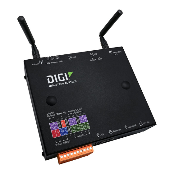
1. Connect one end of the Ethernet cable to the Ethernet port on the front of the Z45 Controller. 2. Connect the other end of the Ethernet cable to the Ethernet port on your computer. Z45 Controller indication/terminations/switches Below is a diagram of the Z45 Controller block terminations. Welcome to Digi SkyCloud... - Page 173 Digital/Pulse Input Configuration on Revision A and B Units: In digital/pulse mode, an internal pull up to 3.3Vdc allows for direct connect of dry contacts. You may also configure an external pull up or digital source of up to 24Vdc if required. Welcome to Digi SkyCloud...
- Page 174 0-5Vdc sources. Analog Inputs on Revision B Units: In analog mode, inputs may be configured for sensing standard 0-5Vdc or 4-20ma sources. Power Input The device requires 9-24v DC. The power input also has reverse polarity protection. Welcome to Digi SkyCloud...
- Page 175 Perform a factory default by holding the default button for 5 seconds, until the Service and Link LEDs blink Orange/Red in unison and release. The device will be set to factory defaults and reboot. LAN Led Welcome to Digi SkyCloud...
-
Page 176: Z45 Controller Digital Inputs
(D6). You can select an appropriate pull up/current limiting resistor value and pull the input up to whatever DC level is required. As described above, contacts or an open collector/open drain output can then pull the input to ground. Examples of both are shown below. Welcome to Digi SkyCloud... - Page 177 Z45 Controller hardware Z45 Controller Digital Inputs Examples Using Internal 3.3 VDC Pull Up Welcome to Digi SkyCloud...
-
Page 178: Using The Analog Inputs Of The Z45 Controller
Use the Z45 Controller (+) supply to power the sensor. b. Use the Z45 Controller (-) supply to ground the sensor. c. Connect the loop return to the appropriate IN1-IN4 input of the Z45 Controller. Welcome to Digi SkyCloud... -
Page 179: Using The Digital Outputs Of The Z45 Controller
(-) of the Z45 Controller DC supply. It is important to understand the DC characteristics of the external load. In some cases, current limiting will be required. Example using a Z45 Controller Output to Drive a Relay Welcome to Digi SkyCloud... -
Page 180: Rms Kit Hardware
An M2M SIM card is inserted in Slot A by default. Check with your system (Optional) administrator to confirm that the M2M SIM card in the RMS Z45 has been activated. The second SIM card is optional and is used for redundancy. Welcome to Digi SkyCloud... -
Page 181: Accessories Bag
1. Make sure you have the RMS Z45 mounting kit. Remove the set of 4 screws with wall anchors and 4 rubber sealing washers. 2. Unplug the RMS Z45 from the main power supply. 3. Open the enclosure using the enclosure key. Welcome to Digi SkyCloud... - Page 182 7. Place the enclosure on the wall, being careful to line up each mounting foot on the enclosure with an anchor in the wall. 8. Place a rubber sealing washer over each mounting foot. Make sure that the washer completely covers the mounting foot. Welcome to Digi SkyCloud...
-
Page 183: Attach The Rms Z45 To The Din Rail
Connect the power supply to the RMS Z45. Close and lock the hardware. Power the device. Attach the RMS Z45 to the DIN rail If you have detached the RMS Z45 from the DIN rail, you should re-attach RMS Z45 to the DIN rail. Welcome to Digi SkyCloud... -
Page 184: Connect The Power Supply To The Rms Z45
If you wire the power supply in backwards you will not harm the device. The RMS Z45 simply will not power on when plugged into the main power. Step 1: Attach wires to the power supply The RMS Z45 kit comes with a power supply unit and two wires: one black and one red. Welcome to Digi SkyCloud... - Page 185 3. Tighten the screws for both pins. Step 2: Attach power supply to the RMS Z45 1. Orient the RMS Z45 so the front of the device is facing you. 2. Unplug and remove the lower Phoenix connector from the RMS Z45. Welcome to Digi SkyCloud...
-
Page 186: Detach An Accessory From The Rms Z45
4. Plug the lower Phoenix connector back into the RMS Z45. Detach an accessory from the RMS Z45 An accessory that is attached to the 3" DIN rail on the side of the RMS Z45 can be detached. Welcome to Digi SkyCloud... -
Page 187: Detach The Antenna Cables From The Rms Z45
3. Detach the accessory from the DIN rail, following the connection instructions for the accessory. 4. If your process is complete, close and lock the hardware. Otherwise, leave the enclosure open to perform any other items. Detach the antenna cables from the RMS Z45 Both antenna cables should be detached. Welcome to Digi SkyCloud... -
Page 188: Disconnect The Power Supply From The Rms Z45
Pin 1 (negative) and Pin 2 (positive) terminals. Tools needed You will need a Phillips-head screwdriver to loosen and tighten the pins. Follow the process below to disconnect the power supply from the RMS Z45. Welcome to Digi SkyCloud... - Page 189 Use a Phillips-head screwdriver to loosen the screws for Pin 1 and Pin 2. b. Disconnect the black (negative) wire from Pin 1 (negative terminal). c. Disconnect the red (positive) wire from Pin 2 (positive terminal). d. Tighten the screws for Pin 1 and Pin 2. Welcome to Digi SkyCloud...
-
Page 190: Detach The Rms Z45 From The Din Rail
Before you detach the he RMS Z45 from the DIN rail, make sure you have disconnected the device from an external power supply, detached the antennas, and disconnected the internal power supply. If an accessory was attached, that should be detached as well. 1. Orient the RMS Z45 as shown. Welcome to Digi SkyCloud... - Page 191 RMS kit hardware Detach the RMS Z45 from the DIN rail 2. Open the enclosure using the enclosure key. 3. Push down to unclip the RMS Z45 from the DIN rail. Welcome to Digi SkyCloud...
Need help?
Do you have a question about the SkyCloud Z4500 Series and is the answer not in the manual?
Questions and answers