
Related Manuals for Enwork EMERSON


Summary of Contents for Enwork EMERSON
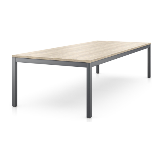
- Page 1 E M E R S O N E M E R S O N T A B L E T I 0 0 6 9 Emerson Table Installation Guide REV A DATE:(7/29/2022)
-
Page 2: Tools And Supplies Required
1) TOOLS AND SUPPLIES REQUIRED Drill Ratchet ½” Socket #3 Phillips Head Driver #2 Square Head Driver T I 0 0 6 9 Emerson Table Installation Guide REV A DATE:(7/29/2022) - Page 3 Work surface attachment Support tube attachment Footer bar tube (EMM-2003) bracket (EMM-1002) bracket (EMM-1007) (EMM-1013) #8 x .75” Phillips Pan head Laminate Footer bar wood screw shelf (EMM-1001) T I 0 0 6 9 Emerson Table Installation Guide REV A DATE:(7/29/2022)
- Page 4 (4) ¼-20 x 50 thread cutting screws. Orient the brackets towards each other as seen in Fig 3.3 **Repeat these steps with the 2 set of leg and crossbar sub assemblies** Fig 3.3 T I 0 0 6 9 Emerson Table Installation Guide REV A DATE:(7/29/2022)
- Page 5 (8) ¼-20 x .50” thread cutting screws as seen in Fig 3.5 Fig 3.5 3.9) For tables with casters, install them into the Corner Legs at this time. Fig 3.6 T I 0 0 6 9 Emerson Table Installation Guide REV A DATE:(7/29/2022)
- Page 6 (1) #10 x 1.00 Wood screw per work surface attachment bracket Fig 3.7 3.13) Flip the completed table assembly right-side 3.14) Adjust levelers as needed Fig 3.8 T I 0 0 6 9 Emerson Table Installation Guide REV A DATE:(7/29/2022)
- Page 7 (4) ¼-20 x .50 Flat head tri-lobe screws 4.5) Repeat these steps for the 3 remaining corner leg weldments Fig 3.9 T I 0 0 6 9 Emerson Table Installation Guide REV A DATE:(7/29/2022)
- Page 8 (1) #10 x 1.00 Wood screw per work surface attachment bracket Fig 4.4 4.9) Flip the completed table assembly right-side 4.10) Adjust levelers as needed Fig 4.5 T I 0 0 6 9 Emerson Table Installation Guide REV A DATE:(7/29/2022)
- Page 9 (4) ¼-20 x .50 thread cutting screws. 5.6) Complete these steps for the 2 set of Corner legs and Crossbar tubes and set them aside. Fig 5.3 T I 0 0 6 9 Emerson Table Installation Guide REV A DATE:(7/29/2022)
- Page 10 Footer bar tubes as seen in Fig 5.6. **Confirm that the holes on the wide side of the Footer bars are facing toward each other** Fig 5.6 T I 0 0 6 9 Emerson Table Installation Guide REV A DATE:(7/29/2022)
- Page 11 Footer bar shelf, attach (3) Worksurface attachment brackets to the Footer bar tube using (2) ¼-20 Pan head thread cutting screws each. 5.17) For Tables 108-120”L, attach (4) Worksurface attachment brackets T I 0 0 6 9 Emerson Table Installation Guide REV A DATE:(7/29/2022)
- Page 12 5.18) Attach the Footer bar shelf to the work surface attachment brackets using (1) 0.75” Pan head wood screw per bracket Refer to Steps 3.10 to 3.14 to finish the table assembly T I 0 0 6 9 Emerson Table Installation Guide REV A DATE:(7/29/2022)
- Page 13 12900 Christopher Drive Lowell, MI 49331 800.815.7251 www.enwork.com Specifications subject to change without notice.
Need help?
Do you have a question about the EMERSON and is the answer not in the manual?
Questions and answers