Chapters
Table of Contents

Related Manuals for Kichler Lighting Lucian II 330241


Summary of Contents for Kichler Lighting Lucian II 330241
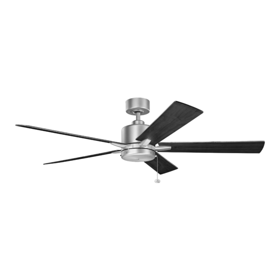
- Page 1 42" , 52" and 60" Lucian II Product images may vary slightly from actual product. INSTRUCTION MANUAL Model#: 330241, 330242, 330243 READ AND SAVE THESE INSTRUCTIONS REV. 28-JULY-2022...
-
Page 2: Table Of Contents
TABLE OF CONTENTS SAFETY RULES ..............3 FINISHING THE INSTALLATION........ 11 TOOLS REQUIRED ............4 ATTACHING THE FAN BLADES .........12 PACKAGE CONTENTS ............4 INSTALLING THE MOUNTING PLATE ....12 MOUNTING OPTIONS .............5 INSTALLING THE SWITCH HOUSING .....13 HANGING THE FAN ............6 OPERATING INSTRUCTIONS ........14 INSTALLATION OF SAFETY SUPPORT .... -
Page 3: Safety Rules
SAFETY RULES 1. CAUTION – RISK OF SHOCK – Disconnect Power at the main 9. WARNING: make sure the power is disconnected before cleaning circuit breaker panel or main fusebox before starting and during the your fan. installation. 10. To avoid personal injury or damage to the fan and other items, be 2. -
Page 4: Tools Required
TOOLS REQUIRED • Phillips Screwdriver • Blade Screwdriver • 11 mm Wrench • Step Ladder • Wire Cutters PACKAGE CONTENTS Unpack your fan and check the contents . You should have the following items: A-1. Fan Blades (5) (42 in.) H. -
Page 5: Mounting Options
MOUNTING OPTIONS If there isn’t an existing UL (cUL for Canadian Installation) listed mounting box, then read the following instructions. Disconnect the power by removing fuses or turning off circuit breakers. Outlet box Secure the outlet box directly to the building structure. Use appropriate fasteners and building materials. -
Page 6: Hanging The Fan
HANGING THE FAN WARNING: All set screws must be checked, and retightened where necessary, before installation. Hanger Bracket REMEMBER to turn off the power before you begin. Ceiling To properly install your ceiling fan, follow the steps below. Canopy Step 1. Remove the decorative canopy bottom cover from the canopy by turning the cover counter clockwise. - Page 7 HANGING THE FAN Cross Pin (continued) Hanger WARNING: All set screws must be checked, and retightened where Ball Set Screw necessary, before installation. Step 5. Remove the hanger ball from the downrod assembly by loosening the Download set screw, unscrewing and removing removing the cross pin and unscrewing the ball off the rod.
- Page 8 HANGING THE FAN (continued) Downrod Step 8. Slip the coupling cover , canopy cover and canopy onto the downrod. (Fig. 9) Canopy Thread the hanger ball onto the downrod, insert the cross pin through the Canopy Cover downrod and tighten. Now tighten the set screw. (Fig. 9) Step 9.
-
Page 9: Installation Of Safety Support
INSTALLATION OF SAFETY SUPPORT (required for Canadian installation ONLY) A safety support cable is provided to help prevent the ceiling fan from falling. Step 1. Attach the wood screw and washers to the ceiling joist next to the Ceiling mounting Attach safety cable mounting bracket but do not tighten. -
Page 10: Electrical Connections
ELECTRICAL CONNECTIONS Power Lines 120V Green WARNING: To avoid possible electrical shock, be sure you have turned Ground off the power at the main circuit panel. Follow the steps below to connect the fan to your household wiring. Use Wiring the wire connecting nuts suppled with your fan. -
Page 11: Finishing The Installation
FINISHING THE INSTALLATION Step 1. Tuck all the connections neatly into the ceiling outlet box. Outlet Box Step 2. Slide the canopy up to the mounting bracket and place one of the key hole slots over the mounting screw on the mounting bracket. Rotate Ceiling the canopy until the screw head locks in place at the narrow section of the Mounting... -
Page 12: Attaching The Fan Blades
ATTACHING THE FAN BLADES CAUTION: To Reduce The Risk Of Electric Shock, Disconnect The Electrical Supply Circuit To The Fan Before Installing Fan Blades. Screws CAUTION: Remove the five rubber shipping blocks attached to the face of the motor. These blocks keep the motor from shifting during shipping and MUST be removed during installation. -
Page 13: Installing The Switch Housing
INSTALLING THE SWITCH HOUSING CAUTION: To Reduce The Risk Of Electric Shock, Disconnect The Electrical Supply Circuit To The Fan Before Installing Switch Housing. Step 1. While holding the switch housing under your ceiling fan, push the square wire connectors together. One from the fan and one from the switch housing. -
Page 14: Operating Instructions
OPERATING INSTRUCTIONS Turn the power on and check the operation of your ceiling fan. The pull chain controls the 3 speeds of your ceiling fan. 1 pull = High, 2 pulls = Medium, 3 pulls = Low and the 4th pull turns the motor off. -
Page 15: Troubleshooting
TROUBLESHOOTING Problem Solution Fan will not start. 1. Check circuit fuses or breakers. 2. Check all electrical connections to ensure proper contact. CAUTION: Make sure the main power is OFF when checking any electrical connection. Fan sounds noisy. 1. Make sure all motor housing screws are snug. 2. - Page 16 KICHLER LIGHTING LLC ® 30455 SOLON ROAD SOLON, OHIO 44139 CUSTOMER SERVICE 866.558.5706 8:00 AM TO 5:00 PM EST, MONDAY - FRIDAY 2022/07/28 © Kichler Lighting LLC. All Rights Reserved.
- Page 17 Lucian II de 42 po, 52 po et 60 po Les images du produit peuvent varier légèrement par rapport au produit réel. MANUEL D’INSTRUCTIONS Modèle nº : 330241, 330242, 330243 LISEZ ET CONSERVEZ CES INSTRUCTIONS REV. 28-JUL-2022...
- Page 18 TABLE DES MATIÈRES RÈGLES DE SÉCURITÉ ..........3 FIN DE L’INSTALLATION ..........11 OUTILS NÉCESSAIRES ..........4 FIXATION DES PALES DU VENTILATEUR ..12 CONTENU DU COLIS ..........4 INSTALLATION DE LA PLAQUE DE MONTAGE ..12 OPTIONS DE MONTAGE ...........5 INSTALLATION DU BOÎTIER DE COMMUTATEUR ..13 SUSPENDRE LE VENTILATEUR ......6 INSTRUCTIONS D’UTILISATION ......
-
Page 19: Règles De Sécurité
RÈGLES DE SÉCURITÉ 1. ATTENTION : RISQUE DE CHOC : Débranchez l’alimentation au 9. AVERTISSEMENT : assurez-vous que l’alimentation est coupée panneau du disjoncteur principal ou à la boîte à fusibles principale avant de nettoyer votre ventilateur. avant de démarrer et pendant l’installation. 10. -
Page 20: Outils Nécessaires
OUTILS NÉCESSAIRES • Tournevis cruciforme • Tournevis à lame • Clé de 11 mm • Escabeau • Pinces coupantes CONTENU DU COLIS Déballez votre ventilateur et vérifiez le contenu. Vous devriez avoir les éléments suivants : A-1. Pales de ventilateur (5) (42 po) Bouchon en plastique A-2. -
Page 21: Options De Montage
OPTIONS DE MONTAGE S’il n’y a pas de boîtier de montage homologué UL (cUL pour installation canadienne), lisez les instructions suivantes. Débranchez l’alimentation en retirant les fusibles ou en désactivant les disjoncteurs. Boîtier de sortie Fixez le boîtier de sortie directement à la structure du bâtiment. -
Page 22: Suspendre Le Ventilateur
SUSPENDRE LE VENTILATEUR AVERTISSEMENT : Toutes les vis de réglage doivent être vérifiées et resserrées si nécessaire avant l’installation. Support de suspension RAPPELEZ-VOUS de couper l’alimentation avant de commencer l’installation. Auvent de Pour installer correctement votre ventilateur de plafond, suivez les étapes plafond ci-dessous. - Page 23 SUSPENDRE LE VENTILATEUR Broche croisée (suite) Boule de AVERTISSEMENT : Toutes les vis de réglage doivent être vérifiées et suspension Vis de réglage resserrées si nécessaire avant l’installation. Étape 5. Retirez la boule de suspension de l’assemblage de la tige Télécharger descendante en desserrant les vis de réglage, en dévissant et retirant la goupille transversale et en dévissant la boule hors de la tige.
- Page 24 SUSPENDRE LE VENTILATEUR (Suite) Tige descendante Étape 8. Glissez le couvercle du couplage, le cache de l’auvent et l’auvent sur la tige descendante. (Fig. 9) Auvent Enfilez la boule de suspension sur la tige descendante, insérez la tige Cache de l’auvent transversale à...
-
Page 25: Installation Du Support De Sécurité
INSTALLATION DU SUPPORT DE SÉCURITÉ (requis pour l’installation au Canada SEULEMENT) Un câble de support de sécurité est fourni pour aider à empêcher le ventilateur de plafond de tomber. Support de montage Fixez le câble de Étape 1. Fixez la vis à bois et les rondelles à la solive de plafond à côté du support au plafond sécurité... -
Page 26: Raccordements Électriques
RACCORDEMENTS ÉLECTRIQUES Lignes électriques 120 V Fil de AVERTISSEMENT : Pour éviter tout risque d’électrocution, assurez- terre vert vous d’avoir coupé l’alimentation au panneau de circuit principal avant de procéder au câblage. Boîtier de Suivez les étapes ci-dessous pour raccorder le ventilateur à votre câblage câblage domestique. -
Page 27: Fin De L'installation
FIN DE L’INSTALLATION Étape 1. Rentrez soigneusement toutes les connexions dans la boîte de sortie au plafond. Boîtier de sortie Étape 2. Faites glisser l’auvent jusqu’au support de montage et placez Support de l’une des fentes du trou de serrure sur la vis de montage du support de montage au plafond montage. -
Page 28: Fixation Des Pales Du Ventilateur
FIXATION DES PALES DU VENTILATEUR ATTENTION : Pour réduire le risque de choc électrique, débranchez le circuit d'alimentation électrique du ventilateur avant d'installer les pales du ventilateur. ATTENTION : Retirez les cinq blocs d’expédition en caoutchouc fixés à la face du moteur. Ces blocs empêchent le moteur de se déplacer pendant Rondelles de fibre l’expédition et DOIVENT être retirés pendant l’installation. -
Page 29: Installation Du Boîtier De Commutateur
INSTALLATION DU BOÎTIER DE COMMUTATEUR ATTENTION : Pour réduire le risque de choc électrique, débranchez le circuit d’alimentation électrique du ventilateur avant d’installer boîtier d’interrupteur. Étape 1. Tout en tenant le boîtier d’interrupteur sous votre ventilateur de plafond, poussez les connecteurs carrés des fils ensemble. Un pour le ventilateur et un pour le boîtier d’interrupteur. -
Page 30: Instructions D'utilisation
INSTRUCTIONS D’UTILISATION Rétablissez le courant et vérifiez le fonctionnement de votre ventilateur de plafond. La chaîne de traction commande les 3 vitesses de votre ventilateur de plafond. Tirer 1 fois = Élevé, tirer 2 fois = Moyen, tirer 3 fois = Bas et tirer 4 fois éteint le moteur. -
Page 31: Dépannage
DÉPANNAGE Problème Solution Le ventilateur ne 1. Vérifiez les fusibles ou les disjoncteurs. démarre pas. 2. Vérifiez tous les raccordements électriques pour assurer un bon contact. ATTENTION : Assurez-vous que l’alimentation principale est coupée lors de la vérification de tout raccordement électrique. - Page 32 KICHLER LIGHTING LLC ® 30455 SOLON ROAD SOLON, OHIO 44139 SERVICE À LA CLIENTÈLE 866.558.5706 8 h à 17 h EST, DU LUNDI AU VENDREDI 2022/07/28 © Kichler Lighting LLC. Tous droits réservés.
- Page 33 Lucian II de 42 in, 52 in y 60 in Las imágenes del producto pueden diferir ligeramente del producto real. MANUAL DE INSTRUCCIONES Modelo n.°: 330241, 330242, 330243 LEER Y GUARDAR ESTAS INSTRUCCIONES REV. 28-JUL-2022...
- Page 34 ÍNDICE NORMAS DE SEGURIDAD........3 FINALIZACIÓN DE LA INSTALACIÓN ....11 HERRAMIENTAS NECESARIAS ......4 COLOCACIÓN DE LAS ASPAS DEL VENTILADOR ..12 CONTENIDO DEL PAQUETE........4 INSTALACIÓN DE LA PLACA DE MONTAJE ..12 OPCIONES DE MONTAJE .........5 INSTALACIÓN DE LA CARCASA DEL INTERRUPTOR ... 13 COLGAR EL VENTILADOR ........6 INSTRUCCIONES DE FUNCIONAMIENTO ..
-
Page 35: Normas De Seguridad
NORMAS DE SEGURIDAD 1. PRECAUCIÓN: RIESGO DE DESCARGA ELÉCTRICA. Desconecte 8. Evite colocar objetos en el camino de las aspas. la energía en el panel del disyuntor principal o en la caja de fusibles 9. ADVERTENCIA: asegúrese de que la corriente esté desconectada principal antes de comenzar y durante la instalación. -
Page 36: Herramientas Necesarias
HERRAMIENTAS NECESARIAS • Destornillador Phillips • Destornillador plano • Llave de 11 mm • Escalera de mano • Cortadores de alambre CONTENIDO DEL PAQUETE Desempaque su ventilador y verifique el contenido. Debería tener los siguientes elementos: A-1. Aspas del ventilador (5) (42 in) Tapón de plástico A-2. -
Page 37: Opciones De Montaje
OPCIONES DE MONTAJE Si no existe una caja de montaje con certificación UL (cUL para la instalación canadiense), lea las siguientes instrucciones. Desconecte la corriente quitando los fusibles o apagando los disyuntores. Caja de salida Fije la caja de salida directamente a la estructura del edificio. Utilice sujetadores y materiales de construcción adecuados. -
Page 38: Colgar El Ventilador
COLGAR EL VENTILADOR ADVERTENCIA: Todos los tornillos de fijación deben revisarse y volverse a apretar cuando sea necesario antes de la instalación. Soporte para colgar RECUERDE desconectar la corriente antes de comenzar la instalación. Dosel de Para instalar correctamente su ventilador de techo, siga los pasos a continuación. techo Paso 1. - Page 39 COLGAR EL VENTILADOR Pasador cruzado (continuación) Bola de ADVERTENCIA: Todos los tornillos de fijación deben revisarse y volverse a suspensión Tornillo de fijación apretar cuando sea necesario antes de la instalación. Paso 5. Retire la bola de suspensión del conjunto de la varilla de extensión Descargar aflojando el tornillo de fijación, desatornillando y quitando el pasador transversal y desatornillando la bola para quitarla de la varilla.
- Page 40 COLGAR EL VENTILADOR (continuación) Varilla de extensión Paso 8. Deslice la cubierta del acoplamiento, la cubierta del dosel y el dosel por la varilla de extensión. (Figura 9) Dosel Enrosque la bola de suspensión en la varilla de extensión, inserte el pasador Cubierta del dosel transversal a través la varilla de extensión y apriete.
-
Page 41: Instalación De Soporte De Seguridad
INSTALACIÓN DE SOPORTE DE SEGURIDAD (requerido para instalación canadiense ÚNICAMENTE) El cable de soporte de seguridad se proporciona para ayudar a evitar que el Soporte de ventilador de techo se caiga. Fije el cable de seguridad montaje del techo a la viga del techo con tornillo y arandela Paso 1. -
Page 42: Conexiones Eléctricas
CONEXIONES ELÉCTRICAS Líneas eléctricas de 120V Conexión a ADVERTENCIA: Para evitar posibles descargas eléctricas, asegúrese de tierra verde haber desconectado la energía en el panel del circuito principal. Siga los pasos a continuación para conectar el ventilador al cableado Caja de doméstico. -
Page 43: Finalización De La Instalación
FINALIZACIÓN DE LA INSTALACIÓN Paso 1. Meta todas las conexiones cuidadosamente en la caja de salida del techo. Caja de salida Paso 2. Deslice el dosel hacia arriba hasta el soporte de montaje y coloque Soporte de una de las ranuras del orificio de la llave sobre el tornillo del soporte de montaje del techo montaje. -
Page 44: Colocación De Las Aspas Del Ventilador
COLOCACIÓN DE LAS ASPAS DEL VENTILADOR PRECAUCIÓN: Para reducir el riesgo de descarga eléctrica, desconecte el circuito de suministro eléctrico al ventilador antes de instalar las aspas. Tornillos PRECAUCIÓN: Retire los cinco bloques de goma de envío unidos a la cara del motor. -
Page 45: Instalación De La Carcasa Del Interruptor
INSTALACIÓN DE LA CARCASA DEL INTERRUPTOR PRECAUCIÓN: Para reducir el riesgo de descarga eléctrica, desconecte el circuito de suministro eléctrico al ventilador antes de instalar la carcasa del interruptor. Paso 1. Mientras sostiene la carcasa del interruptor debajo del ventilador de techo, empuje los conectores de cable cuadrado juntos. -
Page 46: Instrucciones De Funcionamiento
INSTRUCCIONES DE FUNCIONAMIENTO Encienda la corriente y verifique el funcionamiento del ventilador de techo. Mediante la cadena de tracción se controlan las tres velocidades del ventilador de techo. 1 tirón = alto, 2 tirones = medio, 3 tirones = bajo y el cuarto tirón apaga el motor. -
Page 47: Resolución De Problemas
RESOLUCIÓN DE PROBLEMAS Problema Solución El ventilador 1. Verifique los fusibles o disyuntores del circuito. no arranca. 2. Verifique todas las conexiones eléctricas para asegurar un contacto adecuado. PRECAUCIÓN: Asegúrese de que la corriente principal esté APAGADA cuando verifique cualquier conexión eléctrica. El ventilador 1. - Page 48 KICHLER LIGHTING LLC ® 30455 SOLON ROAD SOLON, OHIO 44139 SERVICIO AL CLIENTE 866.558.5706 8:00 A. M. A 5:00 P. M. EST, DE LUNES A VIERNES 28/07/2022 © Kichler Lighting LLC. Todos los derechos reservados.
Need help?
Do you have a question about the Lucian II 330241 and is the answer not in the manual?
Questions and answers