
Subscribe to Our Youtube Channel
Related Manuals for Kichler Lighting Incus


Summary of Contents for Kichler Lighting Incus
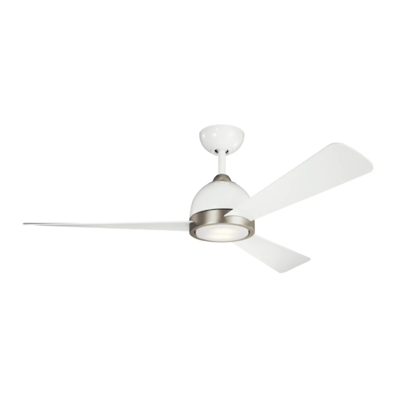
- Page 1 56” Incus™ LED FAN Product images may vary slightly from actual product. Prod INSTRUCTION MANUAL...
-
Page 3: Table Of Contents
FINISHING THE INSTALLATION........MOUNTING OPTIONS............. INSTALLING THE LED ASSEMBLY ..........16 INSTALLING THE WALL TRANSMITTER ......ATTACHING THE FAN BLADES ........7 INSTALLING THE BLADE ARM PLATE ......8 OPERATION INSTRUCTION ..........HANGING THE FAN..............TROUBLESHOOTING............. 56” Incus™ LED FAN | 3... -
Page 4: Safety Rules
SAFETY RULES 1. To reduce the risk of electric shock, insure electricity has been 7. Avoid placing objects in the path of the blades. 8. To avoid personal injury or damage to the fan and other items, be cautious when working around or cleaning the fan. 2. -
Page 5: Tools Required
Blade attachment hardware: Screw (9 + 2 spare) Fiber washer ( 9 + 2 spare) Blade arm plate hardware: Screw (5 + 2 spare) Safety cable hardware: wood screw, spring washer, flat washer Balance Kit 56” Incus™ LED FAN | 5... -
Page 6: Mounting Options
MOUNTING OPTIONS If there isn't an existing UL (cUL for Canadian Installation) listed mounting box, then read the following instructions. Disconnect the Secure the outlet box directly to the building structure. Use appropriate fasteners and building materials. The outlet box and its Outlet box support must be able to fully support the moving weight of the fan (at least 50 lbs). -
Page 7: Attaching The Fan Blades
(Fig.1) Secure the blade with three blade screws and fiber washer fiber washer Blade arm plate slot provided. Step 2. Repeat same process for the remaining blades.(Fig.2) Blades Fig. 1 Fig. 2 56” Incus™ LED FAN | 7... -
Page 8: Installing The Blade Arm Plate
blade arm plate screw INSTALL THE BLADE ARM PLATE blade arm plate Step 1. Align the 5 holes from the blade arm plate to the fan motor assembly. Secure it with the 5 blade arm screws provided. (Fig.3) blade fan motor assembly Fig. -
Page 9: Hanging The Fan
Step 4. Attach the ceiling mounting bracket to the outlet box using the screws and washers included with the outlet box. (Fig.6) UL Listed electrial Ceiling hanger bracket Washers 120V Wires with electrical box) Fig. 6 56” Incus™ LED FAN | 9... - Page 10 HANGING THE FAN (continued) Cross pin Step 5. Remove the hanger ball from the downrod assembly by loosening the set screw, unscrewing and removing the cross Hanger (Fig. 7) ball Set screw Step 6. Loosen the two set screws and remove the hitch pin and retaining clip from the coupling on top of the motor assembly.
- Page 11 WARNING: Failure to reattach the cross pin and seat the "Check Tab" can cause the fan to fall from the ceiling during operation. Take special care to make sure this pin is reattached. Fig. 8 Registration slot Fig. 9 56” Incus™ LED FAN | 11...
-
Page 12: Installation Of Safety Support
INSTALLATION OF SAFETY SUPPORT (required for Canadian installation ONLY) A safety support cable is provided to help prevent the ceiling fan from falling. Step 1. Attach the provided wood screw and washers to the ceiling joist Ceiling mounting next to the mounting bracket but do not tighten. (Fig. 10) bracket Attach safety cable... -
Page 13: Electrical Connections
(Fig. 11) For best performance, make sure the Black Antenna, on the end of the receiver, remains extended and not tangled with any of the electrical Fig. 11 wires. 56” Incus™ LED FAN | 13... - Page 14 ELECTRICAL CONNECTIONS (continued) Outlet box Step 2. Motor to Receiver Electrical Connections: (Fig. 12) Connect the White (neutral) Black (hot) black wire from the fan to the black wire marked "TO MOTOR L" on Green or bare the receiver. Connect the white wire from the fan to the white wire copper (ground) Black ("AC IN L") marked "TO MOTOR N"...
-
Page 15: Finishing The Installation
Failure to properly seat the "Check Tab" could damage the electrical wires when to ceiling fan blade direction is changed while the fan is running. 56” Incus™ LED FAN | 15... -
Page 16: Installing The Led Assembly
INSTALLING THE LED ASSEMBLY NOTE: Before starting installation, disconnect the power by turning switch box Step 1. While holding the LED assembly under your fan ,firmly snap the wire connection plugs together .(Fig.14) Step 2. Attach the LED assembly to the switch box by twisting tightly. (Fig.14) NOTE: This is an integrated LED light kit assembly and can not be... -
Page 17: Installing The Wall Transmitter
WALL CONTROL AC POWER (BLACK) GROUND /EARTH RECEIVER LIVE AC POWER (BLACK) L (BLACK) FOR LIGHT AC POWER (BLUE) (WHITE) N TO MOTOR L (BLACK) TO MOTOR N RECEIVER (WIHTE) Fig. 20 TO CEILING FAN 56” Incus™ LED FAN | 17... -
Page 18: Operation Instruction
OPERATION INSTRUCTION ACTIVATING THE LEARNING PROCESS(Fig.21) faceplate NOTE:The control system for this fan is equipped with a learning frequency function which LEARN has 56K code combinations to prevent potential interference from other remote units. The frequency on your receiver and wall transmitter units have been preset at the factory. No frequency change is necessary. - Page 19 To change the direction of the rotation of the blades,the fan muse be in operation. Warm weather - Forward (counter clockwise) A downward airflow comfort. Cool weather - Reverse (clockwise) An upward airflow moves warm Fig. 23 Fig. 24 56” Incus™ LED FAN | 19...
-
Page 20: Troubleshooting
TROUBLESHOOTING Problem Solution Fan will not start. 1. Check circuit fuses or breakers. 2. Check all electrical connections to insure proper contact. CAUTION: Make sure the main power is OFF when checking any electrical connection. Fan sounds noisy. 1. Make sure all motor housing screws are snug. 2. - Page 21 www.kichler.com KICHLER® LIGHTING 7711 EAST PLEASANT VALLEY ROAD P.O. BOX 318010 CLEVELAND, OHIO 44131-8010 CUSTOMER SERVICE 866.558.5706 8:30 AM TO 5:00 PM EST, MONDAY - FRIDAY...
- Page 22 VENTILADOR CON LED de 56” Incus™ Las imágenes del producto pueden variar levemente respecto del producto real. MANUAL DE INSTRUCCIONES...
- Page 24 INSTALACIÓN DEL TRANSMISOR DE PARED....ACOPLAMIENTO DE LAS ASPAS DEL VENTILADOR ..7 INSTALACIÓN DE LA PLACA DEL BRAZO DEL ASPA..8 INSTRUCCIONES DE FUNCIONAMIENTO....... CÓMO COLGAR EL VENTILADOR ..........LOCALIZACIÓN Y RESOLUCIÓN DE PROBLEMAS ..VENTILADOR CON LED DE 56” Incus™ | 3...
-
Page 25: Normas De Seguridad
NORMAS DE SEGURIDAD 6. Para operar la función inversa en este ventilador, oprima el botón de 1. Para reducir el riesgo de descarga eléctrica, asegúrese de haber sentido inverso mientras el ventilador esté funcionando. cortado el suministro de energía desde el disyuntor o la caja de fusibles antes de comenzar. -
Page 26: Herramientas Requeridas
Arandela de fibra ( 9 + 2 de repuesto) Piezas metálicas de la placa del brazo del aspa: Tornillo (5 + 2 de repuesto) Piezas metálicas del cable de seguridad: tirafondos, arandela de resorte, arandela plana Kit de balanceo VENTILADOR CON LED DE 56” Incus™ | 5... -
Page 27: Opciones De Montaje
OPCIONES DE MONTAJE Si no hay ninguna caja de montaje existente con certificación UL (cUL para instalación en Canadá), entonces lea las siguientes instrucciones. Desconecte el suministro de energía eléctrica retirando los fusibles o apagando los disyuntores. Sujete la caja de distribución directamente a la estructura de la construcción. -
Page 28: Acoplamiento De Las Aspas Del Ventilador
(Fig. 1) Asegure el aspa con los tres tornillos y la arandela Arandela de fibra del brazo del aspa de fibra proporcionados. Paso 2. Repita el mismo proceso con el resto de las aspas. (Fig. 2). Aspas Fig. 1 Fig. 2 VENTILADOR CON LED DE 56” Incus™ | 7... -
Page 29: Instalación De La Placa Del Brazo Del Aspa
Tornillo de la placa del brazo del aspa INSTALACIÓN DE LA PLACA DEL placa del brazo del aspa BRAZO DEL ASPA Aspa Paso 1. Alinee los 5 orificios de la placa del brazo del aspa con el ensamblaje del motor del ventilador. Asegúrelo con los 5 tornillos del brazo del aspa proporcionados. -
Page 30: Cómo Colgar El Ventilador
(Fig.6) Soporte colgante para cielorraso Arandelas Cables de 120 V Tornillos incluidas con la caja de distribución. Fig. 6 VENTILADOR CON LED DE 56” Incus™ | 9... - Page 31 CÓMO COLGAR EL VENTILADOR Pasador transversal (continuación) Paso 5. Retire la bola colgante del ensamblaje del vástago de extensión Bola colgante aflojando los tornillos embutidos, retirando el pasador transversal y Tornillo embutido desenroscando la bola del vástago. (Fig. 7) Vástago de extensión Paso 6.
- Page 32 "pestaña de verificación" no se asienta correctamente, el ventilador podría caer durante el funcionamiento. Debe tomarse todos los Fig. 8 recaudos necesarios para asegurar que el pasador se haya vuelto a enganchar. Ranura de registro Fig. 9 VENTILADOR CON LED DE 56” Incus™ | 11...
-
Page 33: Instalación Del Soporte De Seguridad
INSTALACIÓN DEL SOPORTE DE SEGURIDAD (SE REQUIERE ÚNICAMENTE PARA SU INSTALACIÓN EN CANADÁ) Se incluye un cable de soporte de seguridad que contribuye a evitar que el ventilador de techo se caiga. Paso 1. Acople el tirafondos y las arandelas proporcionados con la viga Soporte de montaje del techo junto al soporte de montaje, pero no ajuste. -
Page 34: Conexiones Eléctricas
(Fig.11) Para un mejor rendimiento, asegúrese de que la antena negra, al final del receptor, continúe extendida y no esté enredada con algún cable Fig. 11 eléctrico. VENTILADOR CON LED DE 56” Incus™ | 13... - Page 35 CONEXIONES ELÉCTRICAS Caja de distribución (CONTINUACIÓN) Paso 2. Conexiones eléctricas del motor al receptor: (Fig.12) Conecte el cable negro Blanco (neutro) del ventilador al cable negro marcado como “TO MOTOR L" (AL MOTOR L) desde el Negro (caliente) Verde o cobre sin receptor.
-
Page 36: Finalización De La Instalación
El asiento incorrecto de la "pestaña de verificación" puede dañar los cables eléctricos cuando la dirección de las aspas del ventilador del techo se modifique con el ventilador en movimiento. VENTILADOR CON LED DE 56” Incus™ | 15... -
Page 37: Instalación Del Ensamblaje De Led
INSTALACIÓN DEL ENSAMBLAJE DE LED NOTA: Antes de comenzar con la instalación, desconecte el suministro de energía eléctrica apagando el disyuntor o retirando el fusible del bloque de fusibles. caja de interruptores Paso 1. Mientras sostiene el ensamblaje de LED por debajo del ventilador de techo, acople los conectores con firmeza entre sí. -
Page 38: Instalación Del Transmisor De Pared
PARA ILUMINACIÓN ALIMENTACIÓN DE CA (AZUL) (BLANCO) N AL MOTOR L (NEGRO) AL MOTOR N RECEPTOR (BLANCO) Fig. 20 AL VENTILADOR DE TECHO VENTILADOR CON LED DE 56” Incus™ | 17... -
Page 39: Instrucciones De Funcionamiento
INSTRUCCIONES DE FUNCIONAMIENTO ACTIVACIÓN DEL PROCESO DE OBTENER INFORMACIÓN (FIG. 21) NOTA:El sistema de control del ventilador está equipado con una función de obtener Placa frontal OBTENER información de frecuencia con 56K posibles combinaciones de códigos para evitar la INFORMACIÓN interferencia desde otras unidades remotas. - Page 40 área del cielorraso tal como se muestra en Fig. 23 la Fig. 24. Esto permite configurar la calefacción en casos de clima más fresco sin afectar su comodidad. Fig. 24 VENTILADOR CON LED DE 56” Incus™ | 19...
-
Page 41: Localización Y Resolución De Problemas
LOCALIZACIÓN Y RESOLUCIÓN DE PROBLEMAS Problema Solución El ventilador no arranca. 1. Controle el funcionamiento de los fusibles de circuito o los disyuntores. 2. Verifique todas las conexiones eléctricas para asegurar el debido contacto. PRECAUCIÓN: Asegúrese de que la corriente principal esté DESCONECTADA al verificar cualquier conexión eléctrica 1. - Page 42 www.kichler.com KICHLER® LIGHTING 7711 EAST PLEASANT VALLEY ROAD P.O. BOX 318010 CLEVELAND, OHIO 44131-8010 SERVICIO DE ATENCIÓN AL CLIENTE 866.558.5706 8:30 AM A 5:00 PM HORA DEL ESTE, DE LUNES A VIERNES...
- Page 43 VENTILATEUR À LED Incus™ 56 po Le produit peut différer légèrement des illustrations. MANUEL D'INSTRUCTIONS...
- Page 45 INSTALLATION DE L'ENSEMBLE LED ........16 INSTALLATION DE L'ÉMETTEUR MURAL....FIXATION DES PALES DE VENTILATEUR ......7 INSTALLATION DE LA PLAQUE DU BRAS DE PALE..8 INSTRUCTIONS D'UTILISATION ........SUSPENSION DU VENTILATEUR ........... DÉPANNAGE ................VENTILATEUR À LED Incus™ 56 PO | 3...
-
Page 46: Consignes De Sécurité
CONSIGNES DE SÉCURITÉ 6. Pour utiliser la fonction inverse sur ce ventilateur, appuyer sur le 1. Pour réduire le risque d'électrocution, assurez-vous que l'électricité a bouton de marche arrière pendant que le ventilateur est en marche. été coupée au niveau du disjoncteur ou de la boîte à fusibles avant de commencer. -
Page 47: Outillage Requis
Rondelle en fibre ( 9 + 2 de rechange) Matériel pour la plaque du bras des pales : Vis (5 + 2 de rechange) Matériel pour câble de sécurité : vis à bois, rondelle élastique, rondelle plate Kit d'équilibrage VENTILATEUR À LED Incus™ 56 PO | 5... -
Page 48: Options De Montage
OPTIONS DE MONTAGE En l'absence d'une boîte de montage homologuée cUL (UL pour les États-Unis), prendre connaissance des instructions suivantes. Débrancher l'alimentation en retirant les fusibles ou en déclenchant les disjoncteurs de la boîte à prises. Fixer la boîte à prises directement sur la structure du bâtiment. Utiliser des attaches et des matériaux de construction appropriés. - Page 49 (Fig. 1). Fixez la pale avec les trois vis de lame et la rondelle en fibre (fournies). Étape 2. Répétez le même processus pour les lames restantes (Fig. 2). Pales Fig. 1 Fig. 2 VENTILATEUR À LED Incus™ 56 PO | 7...
-
Page 50: Installation De La Plaque Du Bras De Pale
vis de la plaque du bras des pales INSTALLATION DE LA PLAQUE DU plaque de bras de pale BRAS DE PALE pale Étape 1. Alignez les 5 trous de la plaque du bras de la pale sur le moteur du ventilateur. -
Page 51: Suspension Du Ventilateur
Étape 4. Fixez le support de montage au plafond à la boîte à prises en utilisant les vis et les rondelles fournies avec la boîte à prises (Fig.6). Support de suspension au plafond Rondelles Fils 120V Vis de montage (fournies avec la boîte Fig. 6 électrique) VENTILATEUR À LED Incus™ 56 PO | 9... - Page 52 SUSPENSION DU VENTILATEUR Goupille transversale (suite) Étape 5. Retirez la boule de suspension de la tige de fixation en desserrant Boule de la vis de blocage, en dévissant et en retirant la goupille transversale et en suspension Vis de pression retirant la boule de la tige (Fig.
- Page 53 Check Tab correctement sous risque de faire tomber le ventilateur du plafond pendant le fonctionnement. Prendre toutes les précautions nécessaires pour s'assurer que cette broche est remise en place. Fente d'installation Fig. 9 VENTILATEUR À LED Incus™ 56 PO | 11...
-
Page 54: Installation Du Support De Sécurité
INSTALLATION DU SUPPORT DE SÉCURITÉ (requis UNIQUEMENT dans le cas d'une installation canadienne) Un câble de support de sécurité est fourni pour empêcher que le ventilateur de plafond ne tombe. Étape 1. Fixez la vis à bois et les rondelles fournies à la solive du plafond à Support de montage côté... -
Page 55: Connexions Électriques
(Fig. 11) Pour optimiser la performance, assurez-vous que l'antenne noire, à l'extrémité du récepteur, reste étendue et qu'elle n'est pas emmêlée avec les fils Fig. 11 électriques. VENTILATEUR À LED Incus™ 56 PO | 13... - Page 56 CONNEXIONS ÉLECTRIQUES Boîte à prises (SUITE) Étape 2. Connexions électriques entre le moteur et le récepteur : (Fig. 12) Blanc (neutre) Noir (sous tension) Vert ou cuivre nu (terre) Connectez le fil NOIR du ventilateur au fil noir marqué "TO MOTOR L" du récepteur. Connectez le fil blanc du ventilateur au fil blanc marqué...
-
Page 57: Fin De L'installation
Si la languette de contrôle n'est pas logée correctement dans la fente d'installation , les fils électriques lorsque la direction des pales du ventilateur change alors que le ventilateur est en marche. VENTILATEUR À LED Incus™ 56 PO | 15... -
Page 58: Installation De L'ensemble Led
INSTALLATION DE L'ENSEMBLE LED REMARQUE: Avant de procéder à l'installation, débrancher l'alimentation en déclenchant le disjoncteur ou en retirant le fusible de la boîte à fusibles. boîtier électrique Étape 1. Tout en maintenant l’ensemble LED sous le ventilateur, enclenchez fermement les fiches de connexion des fils (Fig. 14). Étape 2. -
Page 59: Installation De L'émetteur Mural
à la boite à prises murale. POUR L’ÉCLAIRAGE ALIMENTATION CA (BLEU) (BLANC) N POUR MOTEUR L (NOIR) AU MOTEUR N (BLANC) RÉCEPTEUR AU VENTILATEUR DE PLAFOND Fig. 20 VENTILATEUR À LED Incus™ 56 PO | 17... -
Page 60: Instructions D'utilisation
INSTRUCTIONS D’UTILISATION ACTIVATION DU PROCESSUS D'APPRENTISSAGE (Fig.21) Plaque avant REMARQUE: Le système de contrôle de ce ventilateur est équipé d’une fonction de LEARN fréquence d’apprentissage dotée de combinaisons de 56K codes afin d’empêcher toute (APPRENTISSAGE) interférence provenant d’autres télécommandes. La fréquence du récepteur et de l'émetteur mural a été... - Page 61 Temps chaud - Vers l'avant (sens inverse des aiguilles d'une montre) Un flux d'air confortable vers le bas. Temps frais - En marche arrière (dans le sens des aiguilles d'une montre) Un flux d'air chaud vers le haut. Fig. 23 Fig. 24 VENTILATEUR À LED Incus™ 56 PO | 19...
- Page 62 DÉPANNAGE Problème Solution Impossible de mettre le 1. Vérifiez les fusibles ou disjoncteurs de circuit. ventilateur en marche. 2. Vérifiez tous les raccordements électriques pour garantit un bon contact. MISE EN GARDE : Assurez-vous que l'alimentation principale est COUPÉE lors de la vérification des raccordements électriques.
- Page 63 www.kichler.com KICHLER® LIGHTING 7711 EAST PLEASANT VALLEY ROAD P.O. BOX 318010 CLEVELAND, OHIO 44131-8010 U.S.A. SERVICE À LA CLIENTÈLE 866.558.5706 De 08h30 à 17h (heure normale du l'Est), du lundi au vendredi...
Need help?
Do you have a question about the Incus and is the answer not in the manual?
Questions and answers