Advertisement
Quick Links
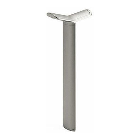
MultipliCITY
Path Light
Assembly Guide
ASSEMBLE WITH CARE! Pangard II Polyester Powdercoat is a strong,
long-lasting finish. To protect this finish during assembly, place
unwrapped powdercoated parts on packaging foam or other non-
marring surface. Do not place or slide powdercoated parts on
concrete or other hard or textured surface – this will damage the
finish causing rust to occur. Use touch-up paint on any gouges in the
finish caused by assembly tools.
Included components:
1x - Base plate
1x - Extrusion
2x – 3/8-16 threaded rod
37-1/4" length for embed mt
34" for surface mt
Tools required for assembly
• Safety glasses
• Flat head screw driver
• 9/16" wrench
• wiring connectors
• compressed air and wire brush
For embedded mount option:
• Anchoring adhesive (Powers Fasteners AC100 Plus™, Hilti™ HIT RE 500 or equivalent)
• masonry drill with bit (diameter recommended by adhesive mfgr for 3/8-16 threaded rod)
For surface mount option:
• Epoxy anchoring system for concrete
• masonry drill with Ø9/16" bit
2x - screw
LED cartridge
concrete anchor
4x - nut
1X – template
LED light head
4x - washer
(surf mt only)
assembly
2X – 3/8-16 x 1" bolt
LIGHTING LAYOUT RECOMMENDATIONS: Refer to the Product Data Sheet
INSTALLATION: Note: Unit must be anchored.
1.
Prepare footing as required by local codes, see Figs. 1 and 2.
2.
Set template in position over conduit.
3.
Mark hole locations and move template
For embedded mount:
4.
Drill holes according to adhesive manufacturer's recommendations. When installed,
threaded rods should extend 4-1/4" below base plate, see Fig. 3.
5.
Using compressed air and wire brush, clear holes of debris.
6.
Place base plate back in position. Install washer, nut and threaded rod as shown in
Fig. 3. Verify top of threaded rod to grade distance is 33".
7.
Move unit. Fill holes with adhesive according to adhesive manufacturer's
recommendations. Do not fill holes to the top.
8.
Slowly set unit back in position.
9.
Wipe away excess adhesive before it begins to cure.
2X - 3/8-16
10. Allow adhesive to fully cure.
11. Fully tighten nuts.
(surface mt)
For surface mount:
4.
Drill holes according to Fig. 4.
5.
Using compressed air and wire brush, clear holes of debris.
6.
Assemble template, concrete anchors and 3/8-16 x 1" hex head bolts as shown in Fig.
10.
7.
Test fit anchors into holes. Make any adjustments to the holes as necessary to allow
anchors to freely install. Anchors should sit centered in hole and not rest against the
sides or bottom of the drilled holes.
8.
Fill anchor holes with epoxy per manufacturer's recommendation.
9.
Slowly set template with anchor assembly into the holes. Wipe away any excess
(surf mt only)
adhesive. Allow epoxy to cure.
10. Remove template and hex head bolts.
11. Install washers and threaded rods. Height from grade to top of installed threaded rod
is 33", see Fig. 4.
12. Fully tighten nuts
Continue embedded and surface mount:
1.
Install extrusion over threaded rods, see Fig. 5.
2.
Make wiring connection.
3.
Open silicone dielectric compound squeeze a generous amount into each wire
terminal before connecting to battery. Use the silicone dielectric compound to
encapsulate the exposed portion of the battery terminals. Set light head assembly
over threaded rods, see Fig 6.
4.
Install washers and nuts onto threaded rods, see Fig. 7. Tighten fully.
5.
Connect wiring from cartridge to wiring connectors.
6.
Set cartridge into place and install screws to secure, see Figs. 8 and 9.
www.landscapeforms.com
.
.
Date: May 21, 2021
Ph: 800.521.2546
Page 1 of 3
Advertisement

Related Manuals for Landscape Forms MultipliCITY Path Light


Summary of Contents for Landscape Forms MultipliCITY Path Light
- Page 1 MultipliCITY Path Light Date: May 21, 2021 Assembly Guide www.landscapeforms.com Ph: 800.521.2546 LIGHTING LAYOUT RECOMMENDATIONS: Refer to the Product Data Sheet ASSEMBLE WITH CARE! Pangard II Polyester Powdercoat is a strong, INSTALLATION: Note: Unit must be anchored. long-lasting finish. To protect this finish during assembly, place unwrapped powdercoated parts on packaging foam or other non- Prepare footing as required by local codes, see Figs.
- Page 2 MultipliCITY Path Light Date: May 21, 2021 Assembly Guide www.landscapeforms.com Ph: 800.521.2546 1-1/2” MAX 2” MIN 37-1/4” LONG THREADED RODS WASHER 36” OR FROSTLINE BASE PLATE WHICHEVER IS DEEPER SIDEWALK EXPANSION JOINT Fig. 1 – sidewalk setback and conduit access Fig.
- Page 3 MultipliCITY Path Light Date: May 21, 2021 Assembly Guide www.landscapeforms.com Ph: 800.521.2546 3/8-16 x 1” HEX HEAD SCREW SCREW TEMPLATE CONCRETE GRIP Fig. 9 – secure top casting ANCHOR Fig. 8 – install top casting Fig. 10 – template assembly for surface mount option WIRING DIAGRAMS: The following schematics are to be used to connect the unit to line voltage.
Need help?
Do you have a question about the MultipliCITY Path Light and is the answer not in the manual?
Questions and answers