Table of Contents
Advertisement
Quick Links
Ashbery
Wall mount light
Installation Guide
Included components
No Twist‐lock
With Twist‐lock
Wall mt luminaire
4X – M8 x 12mm
2X – M10 x 45mm
Hex head bolt
Socket hd
With thread patch
Cap screw
Tools Required
• Safety glasses
• 13mm socket and ratchet wrench
• 8mm hex key
• Wiring tools and connectors
• Twist lock photo eye control, if required
• Phillips screwdriver
• Hardware to mount bracket plate to wall. Bracket has (10) Ø17/64" holes to allow
for anchoring in at least 4 places – see Fig. 3. Max clearance for anchor bolts is 3/8".
• Silicone sealer
ASSEMBLE WITH CARE! Pangard II Polyester Powdercoat is a strong, long‐lasting finish. To
protect this finish during assembly, place unwrapped powdercoated parts on packaging foam or
other non‐marring surface. Do not place or slide powdercoated parts on concrete or other hard or
textured surface – this will damage the finish causing rust to occur. Use touch‐up paint on any
gouges in the finish caused by assembly tools.
Wall mount
Bracket plate
Bracket
4X – 5/16 washer
2X – M8 x 30mm
Socket Hd Cap Screw
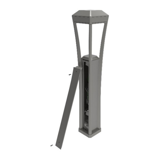
Used for wiring inspection
WARNING! Installer must provide strain relief to line‐in wires where they connect to light
fixture wires. Failure to do so may cause electrical failure and will void warranty.
Landscape Forms is not responsible for site preparation.
INSTALLATION PROCEDURE:
Note: The wall mount luminaire may also be connected to the wall mount bracket first,
and then the assembly can be attached to the bracket plate.
To attach the bracket plate to the wall:
Note: For new installations, it is recommended that a single‐gang outlet box be mounted
horizontally in the wall. The outside face of the box should be flush with the wall or
protrude no more than 1/8" for best results. Since wall mounting substrates vary greatly,
the installer should determine the appropriate fasteners to use to attach the bracket plate
to the wall.
1.
Set bracket plate in position on the wall. See Fig. 3.
2.
Mark hole locations. It is recommended that at least 2 of the holes from the top 5
locations and 2 holes from the bottom 5 locations are used for anchoring.
3.
Move bracket plate.
4.
Drill holes according to anchor manufacturer's recommendations.
5.
Run wires through wiring access hole in bracket plate.
6.
Apply bead of silicone to back of bracket plate as shown in Fig. 4 to ensure the plate
seals to the single‐gang box and the wall.
7.
Place bracket plate in position and install anchors.
To attach wall mount bracket to bracket plate:
Note: Hardware is included to attach wall mount bracket to bracket plate.
1.
Wall mount bracket is shipped pre‐wired. Make wiring connections from the wall
mount bracket to the line‐in voltage wires.
2.
Set wall mount bracket in position over bracket plate
3.
Attach using M8 hex head screws and 5/16 washers as shown in Fig. 5.
To attach luminaire to wall mount bracket:
Note: Hardware is included to attach luminaire to bracket.
1.
Connect the wiring harness from the luminaire to the wall mount bracket as shown in
Fig. 1 and 2.
2.
Push excess wire into the arm of the wall mount bracket.
3.
Align the arm of the luminaire labeled "FRONT" opposite of the arm of the wall
mount bracket.
4.
Verify that the wires will not pinch when nesting the luminaire into the wall mount
bracket cup.
5.
Install the M10x45mm socket head caps screws as shown in Fig. 6.
Date: October 27, 2017
www.landscapeforms.com
Ph: 800.521.2546
Page 1 of 4
Advertisement
Table of Contents

Related Manuals for Landscape Forms Ashbery


Summary of Contents for Landscape Forms Ashbery
- Page 1 Ashbery Wall mount light Date: October 27, 2017 Installation Guide www.landscapeforms.com Ph: 800.521.2546 Included components WARNING! Installer must provide strain relief to line‐in wires where they connect to light fixture wires. Failure to do so may cause electrical failure and will void warranty. Landscape Forms is not responsible for site preparation. INSTALLATION PROCEDURE: Note: The wall mount luminaire may also be connected to the wall mount bracket first, and then the assembly can be attached to the bracket plate. To attach the bracket plate to the wall: Wall mount Bracket plate No Twist‐lock With Twist‐lock Note: For new installations, it is recommended that a single‐gang outlet box be mounted Bracket Wall mt luminaire horizontally in the wall. The outside face of the box should be flush with the wall or protrude no more than 1/8” for best results. Since wall mounting substrates vary greatly, the installer should determine the appropriate fasteners to use to attach the bracket plate to the wall. Set bracket plate in position on the wall. See Fig. 3. Mark hole locations. It is recommended that at least 2 of the holes from the top 5 4X – 5/16 washer locations and 2 holes from the bottom 5 locations are used for anchoring. 4X – M8 x 12mm 2X –...
- Page 2 Ashbery Wall mount light Date: October 27, 2017 Installation Guide www.landscapeforms.com Ph: 800.521.2546 HARDWARE SHOWN FOR REFERENCE (NOT INCLUDED) WIRING Fig. 1 – wall mount luminaire wiring components ACCESS HOLE Fig. 4 – Wall mount silicone location Fig. 3 – Wall mount bracket details Fig. 2– Wall mount luminaire to bracket wiring connection Fig. 6 – Attach luminaire to wall bracket Fig. 5 – Attach wall mount bracket to bracket plate Page 2 of 4...
- Page 3 Ashbery Wall mount light Date: October 27, 2017 Installation Guide www.landscapeforms.com Ph: 800.521.2546 PROCEDURE FOR WIRING ASHBERY: The Ashbery luminaire is assembled at the factory. The light cartridge is mounted into the head of the luminaire and will not need to be removed during installation. The LED cartridge is wired to the driver (located in the base of the luminaire) at the factory. Use of LED drivers other than the supplied unit is not recommended and will void the warranty. The wiring schematics reference connections in the luminaire and connector(s) used to attach to the harness in the wall mount bracket. Connection hardware not included. Installers are responsible for line‐in connections. Optional dimming control is not included. Note: This unit is pre‐wired. These diagrams are for reference to the 3‐pin and 2‐pin connectors. WIRING DIAGRAM: Type 3 luminaire, wall mount, no twist‐lock receptacle WIRING DIAGRAM: Type 3 luminaire, wall mount, with twist‐lock receptacle Page 3 of 4...
- Page 4 Ashbery Wall mount light Date: October 27, 2017 Installation Guide www.landscapeforms.com Ph: 800.521.2546 For inspection purposes: WARNING! Installer must provide strain relief to line‐in wires where they connect to light fixture wires. Failure to do so may cause electrical failure and will void warranty. Landscape Forms is not responsible for site preparation. INSTALLATION PROCEDURE: WARNING! Do not hang or put additional load on the light fixture once it is tipped out and hanging for inspection. Damage to mount bracket or light fixture may occur. 2X – M8 x 30mm To ready unit for inspection: Socket Hd Cap Screw Remove the two bottom M8 hex head screws and washers. Used for wiring inspection Install two M8 x 30mm socket head cap screws in the two bottom holes of the bracket until they bottom out. Remove the top M8 hex head screws while supporting the light fixture to keep it from tipping. Slide the fixture out slowly until it contacts the heads of the bottom two screws. Allow the fixture to slowly tip forward until it rests on the bottom two screws. Hook up / Inspect the wiring. Once inspection is complete, tip unit back to level and slide back to the bracket Fig. 7 – Install special screws for wiring inspection purposes mount plate. Ensure wires are not pinched against the box or the bracket. Reinstall the two M8 hex head screws and washers at the top of the bracket.
Need help?
Do you have a question about the Ashbery and is the answer not in the manual?
Questions and answers