Advertisement
Quick Links
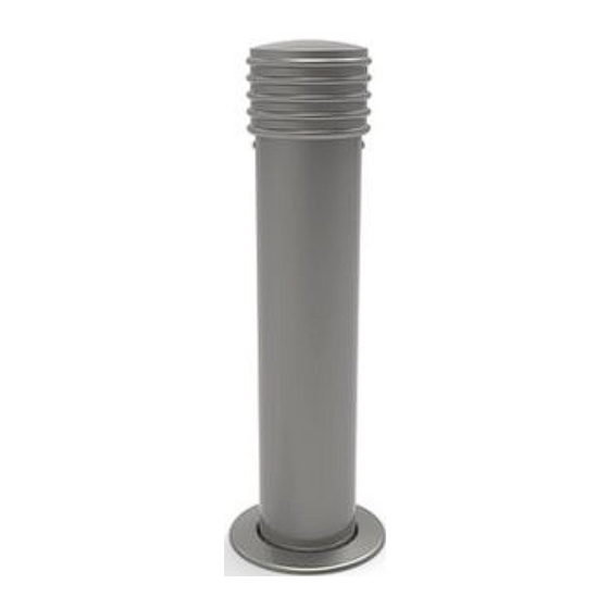
Annapolis
Bollard
Installation Guide
6in
surface
mount
6in
embedded
Tools Required
• 3/16" hex key (for non‐solar bollard without sleeve)
• 1/4" hex key (for non‐solar bollard with sleeve)
• Surface mount bollard: The surface mount bollard has a 3/8" thick mounting plate
that can accept 4 anchors up to 1/2" thread size. If stud anchors are used, select an
anchor length that allows the stud to extend 1" above the mounting surface. Non‐
corrosive anchoring hardware recommended.
• rebar for footing, if required
• drain tubing to engineered fill, if required
CAUTION! Fixtures and wiring must be installed in accordance with local codes and
ordinances. Do not install lighted bollards within 10 feet of a pool, spa, or fountain.
NOTES:
•
Locate bollard where solar light receives an average of 4 hours of direct sunlight per
day. Avoid locations that would become shaded as the path of the sun changes with
the seasons. Solar powered light is not suitable for installation at latitudes greater
than 50 degrees.
Landscape Forms is not responsible for site preparation, footings, or electrical wiring.
•
•
The solar light should not be activated until the bollard is ready to be installed in a
location where it will receive required exposure to sunlight.
•
Failure to allow for proper drainage may void the standard Landscape Forms
warranty.
ASSEMBLE WITH CARE! Pangard II Polyester Powdercoat is a strong, long‐lasting finish. To
protect this finish during assembly, place unwrapped powdercoated parts on packaging foam or
other non‐marring surface. Do not place or slide powdercoated parts on concrete or other hard or
textured surface – this will damage the finish causing rust to occur. Use touch‐up paint on any
gouges in the finish caused by assembly tools.
6in
12in
removable
embedded
1.
Remove top retaining screws, top casting, optional plastic sleeve, and cover ring from
bollard to be mounted. See Fig. 1 and Fig. 5.
PROCEDURE FOR EMBEDDED INSTALLATION, WITHOUT LIGHT:
2.
Embed bollard tube in a concrete footing that meets local frost conditions. Be sure to
allow for proper drainage. See Fig. 2 and Fig. 3.
3.
Clean concrete from bollard tube before it sets. Allow concrete to cure.
PROCEDURE FOR INSTALLATION WITH LED LIGHT:
1.
Complete steps 1‐6 for surface mount installation or steps 1‐3 for embedded.
2.
Unpack the LED light fixture. Refer to light manufacturer's instructions packed with
fixture.
3.
WITH POWER OFF, connect fixture wires to supply wires using approved local
electrical code standard connectors.
4.
Attach LED light assembly to LED mounting bracket with two 8‐32 x 1/2" socket button
head cap screws. Tighten securely. See Fig. 4 and Fig. 6.
5.
Feed fixture wire into bollard. Using two 8‐32 x 1/2" button head cap screws, attach
LED light assembly to retainer bracket. Tighten securely.
PROCEDURE FOR SURFACE MOUNT INSTALLATION, WITHOUT LIGHT:
2.
Place bollard in the desired position and mark hole locations. See Fig. 6.
3.
Move bollard to allow access for drilling holes..
4.
Drill holes at marked locations according to anchor manufacturer's specification.
5.
Clear holes of debris.
6.
Complete the anchor installation according to the anchor manufacturer's instructions.
FINAL INSTALLATION STEP:
1.
Assemble remaining components. Align holes in top casting with threaded holes for
retaining screws. Retaining screws should pass through holes in top casting.
PROCEDURE FOR SOLAR LIGHT INSTALLATION:
1.
Remove top retaining screws, top casting with solar light, optional plastic sleeve, and
cover ring from bollard to be mounted. Solar light and battery bracket remain attached
to top casting with wing nuts.
NOTE: Solar bollards are shipped with a pin‐in‐hex key for security screws. Do NOT connect
the battery wire until Step 4.
2.
Complete surface mount installation steps 1‐6 or embedded installation steps 1‐3.
3.
Assemble cover ring and optional sleeve.
4.
Set battery on shelf of bracket and secure with Velcro strap.
5.
Connect red battery wire to red (positive) battery terminal, see Fig. 7. Connect black
battery wire to black (negative) terminal.
6.
Assemble top casting with solar light and battery to the bollard tube. Align holes in
top casting with threaded holes for retaining screws. Retaining screws should pass
through holes in top casting.
Date: July 20, 2018
www.landscapeforms.com
Ph: 800.521.2546
Page 1 of 4
Advertisement

Related Manuals for Landscape Forms Annapolis Bollard


Summary of Contents for Landscape Forms Annapolis Bollard
- Page 1 Annapolis Bollard Date: July 20, 2018 Installation Guide www.landscapeforms.com Ph: 800.521.2546 Remove top retaining screws, top casting, optional plastic sleeve, and cover ring from bollard to be mounted. See Fig. 1 and Fig. 5. PROCEDURE FOR EMBEDDED INSTALLATION, WITHOUT LIGHT: Embed bollard tube in a concrete footing that meets local frost conditions. Be sure to allow for proper drainage. See Fig. 2 and Fig. 3. Clean concrete from bollard tube before it sets. Allow concrete to cure. 6in PROCEDURE FOR INSTALLATION WITH LED LIGHT: surface Complete steps 1‐6 for surface mount installation or steps 1‐3 for embedded. mount 6in 6in Unpack the LED light fixture. Refer to light manufacturer’s instructions packed with 12in removable embedded fixture. embedded WITH POWER OFF, connect fixture wires to supply wires using approved local electrical code standard connectors. Tools Required Attach LED light assembly to LED mounting bracket with two 8‐32 x 1/2” socket button • 3/16” hex key (for non‐solar bollard without sleeve) head cap screws. Tighten securely. See Fig. 4 and Fig. 6. • 1/4” hex key (for non‐solar bollard with sleeve) Feed fixture wire into bollard. Using two 8‐32 x 1/2” button head cap screws, attach •...
- Page 2 Annapolis Bollard Date: July 20, 2018 Installation Guide www.landscapeforms.com Ph: 800.521.2546 TOP CASTING TOP CASTING HEIGHT O‐RING ABOVE (2) #8‐32 X ½” GRADE SCREWS LED FIXTURE EXPANSION LED FIXTURE JOINT OPTIONAL BOLLARD SHIPS BRACKET PLASTIC SLEEVE WITH BRACKET [457mm] CONCRETE MOUNTED, 24” MIN CONNECTORS 18” SHOWN FOR LED OR FROST REBAR THROUGH LINE MOUNTING Ø1” HOLE CLARITY ONLY ENGINEERED FILL TO ALLOW...
- Page 3 Annapolis Bollard Date: July 20, 2018 Installation Guide www.landscapeforms.com Ph: 800.521.2546 BOLLARD SHIPS WITH BRACKET MOUNTED, TOP SHOWN FOR LED MOUNTING CLARITY ONLY CASTING LED FIXTURE O‐RING (2) #8‐32 X ½” SCREWS LED FIXTURE BATTERY RED BATTERY BRACKET OPTIONAL WIRE PLASTIC SLEEVE CONNECTORS COVER FIG.7 ‐ BATTERY CONNECTION RING SUPPLY WIRES CONCRETE SCREW SURFACE MOUNT BOLLARD TUBE ANCHOR BOLT 4 REQUIRED BY OTHERS SURFACE FIG. 6 ‐...
- Page 4 Annapolis Bollard Date: July 20, 2018 Installation Guide www.landscapeforms.com Ph: 800.521.2546 WARNING! TO AVOID INJURY TO PERSONS HANDLING BOLLARD, USE TWO PEOPLE TO TEAM LIFT AND CARRY BOLLARD. Weight of bollard is 75lbs. SOCKET COVER PLATE CROSS PROCEDURE FOR EMBEDDING THE REMOVABLE BOLLARD SOCKET: Excavate for socket footing and install drain, see Fig. 8. Depth of socket is 18 inches. Depth of footing is minimum 24 inches or as frost conditions require. Before pouring concrete, make sure the factory‐installed tape covers the outside of the hole near the upper end of the socket. Make sure lower end of socket is COVER PLATE PIN sealed to prevent concrete from entering. PVC cap make be cut to fit drain connection. LOCK PLAN VIEW LOCATION PROCEDURE FOR INSTALLING REMOVABLE BOLLARD: Remove socket cover plate and separate halves. (Hint: use a flat blade screwdriver to pry up edge opposite cover plate pin.) Store socket cover plate below cross bar inside socket. Use key to open bollard latch (key horizontal). Remove key. RETAINING Position bollard near socket and align three slots in bollard with bars in socket. SCREW COVER RING Ease bollard into socket. Twist until bars fit into slots. CAUTION! Dropping bollard into socket may damage bollard or socket. CONCRETE Adjusting screws may be used to adjust fit between bollard and socket. Be sure FOOTING ADJUSTING SCREWS locknuts are tight.
Need help?
Do you have a question about the Annapolis Bollard and is the answer not in the manual?
Questions and answers