Advertisement
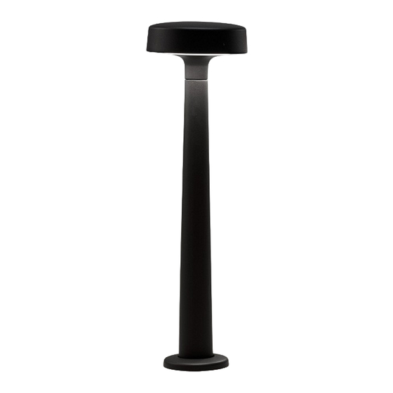
Motive
Path Light
Installation Guide
Surface Mount
Included hardware
1x – anchor
template
1x – path light
assembly
Tools Required
• Safety glasses
• Screwdrivers
• Wiring tools and connectors
• 1/2" wrench or socket
• Hammer drill, with 1/2" dia bit
• 2mm hex key
• Epoxy anchoring system for concrete
• Wire brush and compressed air for clearing anchor holes
• Standard octagon junction box, installed (not included)
LIGHTING LAYOUT RECOMMENDATIONS:
Path light spacing is the responsibility of others. Refer to the Motive Path Light
Product Data Sheet, available on www.landscapeforms.com, for light
distribution options.
4x – 5/16
washer
4x – concrete
anchor
4x – 5/16-18 x
1" hex hd bolt
ASSEMBLE WITH CARE! Pangard II Polyester Powdercoat is a strong, long-lasting finish. To protect this finish
during assembly, place unwrapped powdercoated parts on packaging foam or other non-marring surface. Do not
place or slide powdercoated parts on concrete or other hard or textured surface – this will damage the finish
causing rust to occur. Use touch-up paint on any gouges in the finish caused by assembly tools.
2-1/2"MAX
RECOMMENDED
CONDUIT CLEARANCE
Fig. 1 – Minimum footing recommendation
Fig. 3 – Base plate detail
www.landscapeforms.com
1/2" – 3/4"
RECOMMENDED
CONDUIT SIZE
Fig. 2 – Recommended setback
[133mm]
Ø5-1/4"
BOLT CIRCLE
FRONT
OF LIGHT
Date: November 19, 2019
Ph: 800.521.2546
SIDEWALK
from sidewalk
Page 1 of 3
Advertisement
Table of Contents

Related Manuals for Landscape Forms Motive


Summary of Contents for Landscape Forms Motive
- Page 1 • Standard octagon junction box, installed (not included) FRONT OF LIGHT LIGHTING LAYOUT RECOMMENDATIONS: Path light spacing is the responsibility of others. Refer to the Motive Path Light Product Data Sheet, available on www.landscapeforms.com, for light distribution options. Fig. 3 – Base plate detail...
- Page 2 Installation Guide www.landscapeforms.com Ph: 800.521.2546 Landscape Forms is not responsible for site preparation and footings. Footing recommendations are included in these instructions. INSTALLATION PROCEDURE FOR PATH LIGHT: INDICATES Prepare footing as required by local codes, see Fig. 1, Fig. 2 and Fig. 5 for recommendations.
- Page 3 Motive Path Light Date: November 19, 2019 Installation Guide www.landscapeforms.com Ph: 800.521.2546 PROCEDURE FOR WIRING PATH LIGHT: The following schematic is to be used to connect the unit to line voltage. It is the responsibility of the installer to make sure that all connections are made in accordance with the NEC and local building codes.
Need help?
Do you have a question about the Motive and is the answer not in the manual?
Questions and answers