Table of Contents
Advertisement
SENTRY
TM
1510A
and Tool Interface Module
with (Optional) Condenser
Installation & Operation Manual
Instruction Manual part number 122162
Revision E – February 2020
© 2020 MKS Instruments, Inc. All rights reserved.
Granville-Phillips
®
is a registered trademark of MKS Instruments, Inc.
SENTRY
TM
is a trademark of MKS Instruments, Inc. All other trademarks
and registered trademarks are the properties of their respective owners.
1
Instruction Manual #122162
Advertisement
Table of Contents

Related Manuals for MKS SENTRY 1510A


Summary of Contents for MKS SENTRY 1510A
- Page 1 © 2020 MKS Instruments, Inc. All rights reserved. Granville-Phillips ® is a registered trademark of MKS Instruments, Inc. SENTRY is a trademark of MKS Instruments, Inc. All other trademarks and registered trademarks are the properties of their respective owners. Instruction Manual #122162...
- Page 2 Notice This product is intended for use by industrial customers and should be serviced only by MKS trained representatives. The service manuals and related materials are provided in English at no charge and are intended for use by experienced technicians. It is the responsibility of the user to obtain and assure the accuracy of any needed translations of manuals.
- Page 3 This document contains confidential proprietary information belonging to MKS Instruments, Inc. This information is not for publication and has been provided to MKS on the condition that it not be copied, reproduced or disclosed, either wholly or in part, to third parties without the expressed written consent of MKS Instruments, Inc.
-
Page 4: Table Of Contents
Table of Contents 1. Safety Information ....................5 2. General Description ....................10 2.1 Part Names and Description ................10 3. Quick Start Guide ....................15 3.1 SENTRY 1510 System Installation Checklist ............. 15 4. Guidelines ......................17 4.1 Installation Guidelines ..................17 4.2 Installation Layout ..................... -
Page 5: Safety Information
Failure to comply with these precautions or with specific warnings elsewhere in this manual violates safety standards of design, manufacture, and intended use of the instrument. MKS Instruments, Inc. disclaims all liability for the customer's failure to comply with these requirements. - Page 6 General Hazards Failure to review the Safety chapter and follow the safety warnings can result in serious injury or death. Do not attempt to perform installation, operation, or maintenance procedures on the product until you have read and understand the information in the Safety Chapter. Read and understand each procedure before performing the procedure.
- Page 7 This equipment contains no user serviceable part. Refer all repairs to MKS. Do not operate this equipment without proper exhaust connections. Safety Alert Labels Safety labels and identification labels are placed on the robot and controller to provide operators with information. This section describes each label and identifies its location. For safety labels, instructions are provided on how to avoid the hazard.
- Page 8 It is the responsibility of the end user to provide sufficient lighting at work to meet local regulations. Operation and Service of this equipment in strict accordance with the methods and procedures supplied by MKS is the responsibility of the Customer. Instruction Manual #122162...
- Page 9 MKS Instruments, Inc. assumes no liability, whatsoever, for any personal injuries or damages resulting from the operation or service of this equipment in any manner inconsistent or contrary to the methods supplied in MKS literature including, but not limited to, manuals, instructions, bulletins, communications, and recommendations.
-
Page 10: General Description
General Description Part Names and Description SENTRY 1510 is a mechanical-based process pressure exhaust controller. It is a pressure regulator designed to respond to static exhaust pressure changes and process flow gas changes in order to maintain a constant process pressure at the tool. ... - Page 11 2.1.1 (Optional) CD-20 Condenser The optional CD-20 Condenser is designed to work with the SENTRY 1510 as an integrated system. The CD-20 is designed to remove moisture from wet processing such as steam oxidation or steam cleaning. Whenever a SENTRY 1510 will see a wet process, a BAI or OEM comparable condenser is required.
- Page 12 Reference Port this port is not currently used on models supplied with this manual. A limited number of models are available with the reference port operational to allow for differential pressure control relative to a pressure other than atmosphere. ...
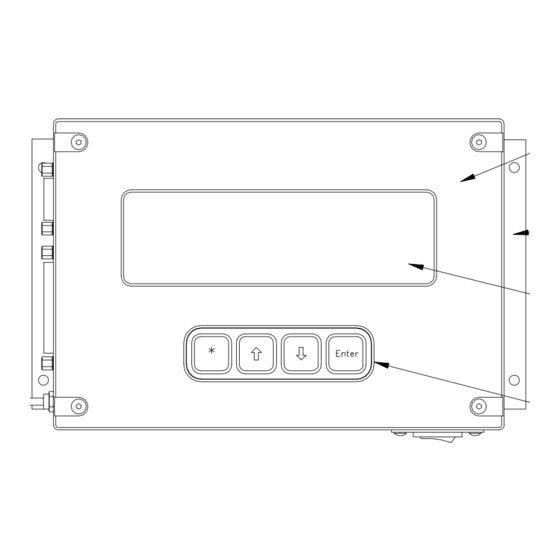
- Page 13 2.1.3 Display TIM-100/200 StptMode Single Pres S 1700 Pres 1713 2540 Selection Indicator An asterisk symbol [*] will appear in the selection indicator box when a menu item is chosen by pressing the asterisk key [*] on the keypad. ...
- Page 14 2.1.4 Keypad (TIM-100/200) Asterisk Key [*] enables a menu item to be modified. When the star key is depressed on the keypad. An [*] will appear in the selection indicator box. & Up Arrow [] and Down Arrow [] Keys allow the user to scroll through the menu items.
-
Page 15: Quick Start Guide
Quick Start Guide If you are familiar with the SENTRY 1510 system and have previously installed the same model, you may wish to make an additional photocopy of this checklist on clean-room paper and refer to it during the installation. Review the notes and cautions located throughout the manual prior to installation. However, if you have not previously installed a SENTRY 1510 system or may have installed a different model, it is recommended that you read through the installation manual in its entirety first and use the checklist during actual installation. - Page 16 [ ] 4.8.1. Mount the Condenser to the Process Tool [ ] 4.8.2. Install the SENTRY 1510 on the Condenser [ ] 4.8.3. Connect the Furnace & Facilities Exhaust to the CD-20 Condenser [ ] 4.8.4. Connect the “AVP” Condenser to the Furnace & Facilities [ ] 4.8.5.
-
Page 17: Guidelines
Guidelines Installation Guidelines Before beginning the design and installation lay out, consider the following general installation features, guidelines and limitations. 1. The SENTRY 1510 controller must remain free of all moisture. For installation on wet process a condenser must be installed in the exhaust path prior to the SENTRY 1510. 2. -
Page 18: Installation Layout
Guidelines Installation Layout The SENTRY 1510 can be ordered as horizontal of vertical installation configuration. Verify you have the correct configuration for your installation and follow the appropriate installation diagrams throughout this manual. Instruction Manual #122162... -
Page 19: Installation & Power-Up
Installation & Power-Up SENTRY 1510 The SENTRY 1510 is available in a horizontally mounted configuration and a vertically mounted configuration. Both versions will be illustrated throughout this manual. Before beginning your installation verify the part number is the appropriate number for your installation. - Page 20 5.1.2 Connecting the Furnace Exhaust (No BAI Condenser) After the SENTRY 1510 is securely mounted, the process tool exhaust can be plumbed to the input side of the SENTRY 1510. If your installation includes a BAI factory condenser please follow the installation guidelines located in the CD-20 condenser section 4.9 of this manual. Notice The process exhaust should not be dampened.
- Page 21 5.1.3 Connecting the Facilities Exhaust to the SENTRY 1510 1. The output of the 1510 is designed to accept 1” male NPT threads. 2. Using thread seal tape install a 1” male NPT compression or other suitable fitting into the output side of the 1510 controller.
-
Page 22: Drains And P-Traps
Drains and P-Traps Drains and p-traps are required on all vertical SENTRY 1510 installations to remove any condensation that may accumulate in the controller. Additionally p-traps and drains are required for furnaces that run wet process regardless of the SENTRY 1510 installation configuration (horizontal or vertical). - Page 23 5.2.2 P-Traps or Tubing Loops 1. Tubing should have a minimum outside diameter of 1/2” (12 mm). 2. Tubing for the SENTRY 1510 drain should have an outside diameter Appropriate to fit a 1/4” NPT fitting. 3. Height of the p-trap or loop should be at least twice the minimum house exhaust. If house exhaust is 100 mm (4”), then the p-trap height should be 200 mm (8”).
-
Page 24: Process Pressure Sense Tube
Process Pressure Sense Tube The process pressure sense tube is a 10’ thin walled Teflon tube (OD 0.25”, ID 0.187). One end of the tube is fitted with a Teflon retainer for securing the tube to the barbed fitting on the SENTRY 1510. -
Page 25: Nitrogen Supply To The Sentry 1510
5.3.2 Connecting the Process Pressure Sense Tube to the SENTRY 1510 1. Connect the process pressure sense tube to the SENTRY 1510 by sliding the end of the tube onto the barb fitting located next to the cable connector on the side of the SENTRY 1510. 2. -
Page 26: Tim 100/120 Installation
TIM 100/120 Installation 5.5.1 Attach the Mounting Brackets to the TIM 100/120 1. Carefully place the TIM 100/120 face down onto a flat surface. 2. Secure both brackets to the TIM 100/120 chassis using the included fasteners (2 each). 3. If the TIM 100/120 has been mounted to a facility structure or the process tool which is not chassis grounded, connect a ground wire lead from the process tool chassis ground to one of the TIM 100/120 mounting brackets as indicated below. -
Page 27: Power Supply
Power Supply Notice MKS systems are sold with and without a power supply. If the system being installed includes the MKS Universal Power Supply, the following applies: • The line voltage requirement of the unit is listed on the power supply label. -
Page 28: Sentry Cable Installation
SENTRY Cable Installation Notice • Cable drawings are provided in the drawings section at the end of this manual. • Both the CE and non-CE cable plugs have alignment keys that must be aligned with the mating panel connector. When the cable plug is fully inserted, lock it in place. - Page 29 5.7.2 Connect the TIM 100/120 Power and/or Tool Interface Depending on the control interface chosen, the system will both require a stand-alone power supply or a tool power and interface cable. Refer to the table below for the appropriate cable connection.
- Page 30 2. Connect the female plug of the power supply cable into the power supply box. 3. Connect the male plug or flying leads of the power supply cable to the appropriate electrical supply. Tool to TIM 100/120 Interface Cable: 1. Connect the interface cable end labeled “P1” to the tool. The connector style varies to accommodate OEM tool connector styles.
-
Page 31: System Start-Up
1. Turn OFF the TIM 100/120 and disconnect the power cable. 2. Connect the RJ12 connector on the serial communications cable to the corresponding socket on the TIM 100/120. 3. Adjust the hexadecimal address as needed. This value is preset at the factory to “00”. 4. - Page 32 5.8.2 Select Communication Operating Mode The TIM-100 communication operating mode must be selected before set points can be properly received and interpreted. The TIM 120 is factory pre-configured. 1. Using the up [] or down [] arrow keys on the SENTRY TIM-100 keypad, scroll through the menu parameters until “STPT MODE”...
-
Page 33: Condenser (Required For Wet Process)
Condenser (Required for Wet Process) The CD-20 and “AVP” condensers are designed to incorporate the SENTRY 1510 for wet processing. Described below are the basic steps for installing the CD-20 condenser and the “AVP” condenser. As with all wet processing drains and p-traps will be required, the “AVP” incorporates a self contained drain. - Page 34 5.9.2 Installing the SENTRY 1510 on the CD-20 or “AVP” Condenser The CD-20 Condenser has two 1” radial seal grooves machined into the input and output blocks. O-rings installed in these grooves create a radial seal between the body of the SENTRY 1510 and the input and output blocks of the condenser.
- Page 35 5.9.3 Connect the Furnace and Facilities Exhaust to the CD-20 Condenser Refer to section 4.8.4 for connecting the “AVP” condenser. The following section details only the immediate connections required for the input and output of the CD-20 condenser. Other facilities requirements are identical to that of installations detailed previously in this manual, such as the drain requirements, process pressure sense line installation, nitrogen supply and cabling.
- Page 36 5.9.4 Connect the “AVP” Condenser to the Furnace & Facilities Shown below is the fully assembled “AVP” condenser. The tubing and fittings required to mate the process output to the input of the “AVP” condenser are not pre-assembled. These parts are intended to be custom fit upon installation of the condenser to the furnace.
- Page 37 6. Connect the process pressure sense tube to the barbed fitting located on the SENTRY 1510 and slide the plastic retainer over the fitting to secure in place. Notice Make sure the Nitrogen supply to the SENTRY 1510 is OFF when connecting the process pressure sense line.
- Page 38 Notice Do not install a flow restrictor or flow controller downstream of the water outlet. Allow the output to flow freely to a drain or recirculation unit. Instruction Manual #122162...
-
Page 39: Operation
Operation Introduction The SENTRY 1510 pressure controller is designed to maintain a constant pressure in a sealed process chamber, compensating for varying process gas flows and fluctuating house exhaust. There are three essential elements that make up the SENTRY system: (1) the mechanical piston based 1510, (2) the microprocessor based TIM 100/120 and (3) the CD-20 condenser for wet processing. - Page 40 a force in the horizontal plane. With no force of gravity (F ) acting in this plane the spring force ) becomes the effective weight of the piston. 6.2.3 Force of Atmospheric Reference The third force acting on the piston is that of atmosphere (F ) providing a reference pressure to the top of the piston.
-
Page 41: Manual ("Single") Mode Sentry Controller With Tim-100/120
6.2.5 Affect of Forces on the Piston The piston’s position forms a gap in the air flow path effectively creating an infinitely variable resistor at the piston edge that responds mechanically to changes in exhaust pressure. For a given process pressure and facility exhaust pressure, the piston will maintain a constant gap in the air flow path. - Page 42 Notice • Any change made to a menu item is only activated after the enter key is depressed. • Any change made to the menu item is only stored in memory until the next time the TIM-100/120 is powered OFF and ON. To permanently store values in memory, follow the steps in Section 4.7.3 of this manual.
-
Page 43: Analog Interfaced Operation
Analog Interfaced Operation When the SENTRY system is configured for analog operation, the process exhaust pressure set points are entered through the process tool. The analog interface operates on a standard 0 to 5 volt full scale (equivalent to 0 to 25.40 mm H O or 0 to 50.80 mm H O) command signal. -
Page 44: Maintenance & Troubleshooting
Maintenance & Troubleshooting Maintenance 7.1.1 Scheduled Maintenance There is no scheduled maintenance for either the SENTRY 1510 or the TIM 100/120. The innovative and simple design of the SENTRY system allows for years of dependable, maintenance-free service. Troubleshooting Many problems associated with the SENTRY 1510 or TIM 100/120 can be traced to improper setup, installation or cabling. - Page 45 Maintenance & Troubleshooting Problem Possible Cause Corrective Action (Section) TIM 100/120 Power not supplied Connect power. (5.7.2) display not on Both positive and The negative voltage (-15 to -24 V negative voltage lines @ 50 mA) powers the display. not supplied Supply voltage according to the appropriate cable drawing in the Drawings section at the end of the...
- Page 46 7.2.1 Measured Exhaust is Not Stable Is the TIM-100/120 power Control unstable Turn on TIM-100/120 Control unstable Are all downstream Set Gain to Zero dampers fully open? Fully open all dampers. Control stable ststable Is the P-Trap filled with fluid Fill P-Trap or close isolation or drain isolation valve Reduce “Gain Fine”...
- Page 47 7.2.2 Measured Process Pressure is Greater than Set Point Is the TIM-100/120 power on? Turn on TIM-100/120 power Set TIM-100/120 Is the TIM-100/120 Parameter Parameter StepLim Step Limit Off? to Off Is set point controlled locally at the TIM- 100/120 or via the analog 0-5 VDC? Is the desired set point indicated next to PresSP?
- Page 48 7.2.3 Measured Process Pressure is Less than Set Point Is the TIM-100/120 power Turn on TIM-100/120 power Set TIM-100/120 Is the TIM-100/120 Parameter StepLim to Parameter Step Limit Off? Is set point controlled locally at the TIM- 100/120 or via the analog 0-5 VDC? Is the desired set point indicated next to Pres SP?
- Page 49 7.2.4 The SENTRY 1510 Not Responding to Changes from the Electronics Is the TIM-100/120 power Turn on TIM-100/120 power Set TIM-100/120 Is the TIM-100/120 Parameter StepLim to Parameter Step Limit Off? Is the desired set point indicated next to Pres SP? Is set point controlled locally at the TIM-100/120 or via the analog 0-5 VDC? 0-5 VDC...
-
Page 50: Appendices
Appendices Appendix A: Specifications and Facility Requirements English Metric English Metric Specifications Specifications TIM-100/120 The SENTRY TIM-100/120 Performance: contains a cartridge fuse holder Negative Pressure Configuration (Inches H (Pa) for a 5 x 20mm fuse. The fuse is 1 Inch Unit (-3 to -23 mm H -0.12 to -0.9 -29 to -225 a 0.8 amp fuse (BAI P/N 12270). -
Page 51: Appendix B: Sentry 1510 Menu
Appendix B: SENTRY 1510 Menu Application: Negative Pressure Control Version Default Value Note 0-25.4 mm H O; TIM-100 G2.3 X = Not Applicable Menu R = Read Only Software Version: G2.3 “Universal Fast Set HWCtrlLock Disable Capable” CtrlItvl CtrlLock Version Default Value Note FlowCoef... -
Page 52: Appendix C: Recommended System Grounding
Appendix C: Recommended System Grounding Instruction Manual #122162... -
Page 53: Appendix D: Tool/Host To Cable Matrix
SEE TABLE BELOW Host End TIM End Non-CE Host End, SEE TABLE FOR PIN OUT Host End, SEE TABLE FOR PIN OUT 9-PIN DB 10-PIN CONEXALL 10-PIN JAE 9-PIN DB RECEPTACLE RECEPTACLE RECEPTACLE PLUG Appendix D: Tool/Host to Cable Matrix Part Host End Pin TIM-100/120 End... -
Page 54: Appendix E: Dimensional Drawings
Appendix E: Dimensional Drawings SENTRY 1510 Legacy Supervisor TIM-100/120 SENTRY 1510 Vertical Installation Dimensions Instruction Manual #122162... - Page 55 Appendix E: Dimensional Drawings (Continued) 1510 with CD-20 Condenser Dimensions 1510 with AVP Condenser Dimensions Instruction Manual #122162...
- Page 56 SENTRY 1510A and Tool Interface Module With (Optional) Condenser Installation & Operation Manual Customer Service / Technical Support: MKS Global Headquarters 2 Tech Drive, Suite 201 Andover MA, 01810 USA Phone: +1-833-986-1686 Email: insidesales@mksinst.com Visit our website at: www.mksinst.com Instruction Manual part number 122162 Revision E –...
Need help?
Do you have a question about the SENTRY 1510A and is the answer not in the manual?
Questions and answers