
Related Manuals for MKS HPS


Summary of Contents for MKS HPS
- Page 1 Two-Stage Valve Service Manual 651 Lowell Street Methuen, MA 01844 Main Telephone: (800) 227-8766 p/n 1061054 www.mksinst.com Rev. 001...
- Page 2 All rights reserved. No part of this work may be reproduced or transmitted in any form or by any means, electronic or mechanical, including photocopying and recording, or by any information storage or retrieval system, except as may be expressly permitted in writing by MKS Instruments, Inc. Printed in the United States of America DeviceNet™...
-
Page 3: Table Of Contents
Customer Support ................................9 Chapter One: General Information ......................10 Introduction ................................. 10 Chapter Two: Servicing an HPS Products Two-Stage Valve ..............11 Disassembly of the main valve ............................ 11 Disassembly and Inspection of Internal Assembly ...................... 12 Disassembly of the bypass valve ..........................14 Disassembly and Inspection of the Bypass Valve ....................... -
Page 5: Valve Safety Information
Failure to comply with these precautions or with specific warnings elsewhere in this manual violates safety standards of intended use of the instrument and may impair the protection provided by the equipment. MKS Instruments, Inc. assumes no liability for the customer’s failure to comply with these requirements. - Page 6 DO NOT SUBSTITUTE PARTS OR MODIFY VALVE Do not install substitute parts or perform any unauthorized modification to the valve. Return the valve to an MKS Calibration and Service Center for service and repair to ensure that all safety features are maintained.
-
Page 7: Sicherheitshinweise Für Das Ventil
Sicherheitshinweise für das Ventil Sicherheitshinweise für das Ventil In dieser Betriebsanleitung vorkommende Symbole Bedeutung der mit WARNUNG!, VORSICHT! und HINWEIS gekennzeichneten Absätze in dieser Betriebsanleitung. Warnung! Das Symbol WARNUNG! weist auf eine Gefahr für das Bedienpersonal hin. Es macht auf einen Arbeitsablauf, eine Arbeitsweise, einen Zustand oder eine sonstige Gegebenheit aufmerksam, deren unsachgemäße Ausführung bzw. - Page 8 Ersetzen Sie keine Teile mit baugleichen oder ähnlichen Teilen, und nehmen Sie keine eigenmächtigen Änderungen am Ventil vor. Schicken Sie das Ventil zwecks Wartung und Reparatur an den MKS-Kalibrierungs- und -Kundendienst ein. Nur so wird sichergestellt, daß alle Schutzvorrichtungen voll funktionsfähig bleiben.
-
Page 9: Informations De Sécurité Relatives Au Manomètre
Informations de sécurité relatives au manomètre Informations de sécurité relatives au manomètre Symboles utilisés dans ce manuel d’utilisation Définitions des indications AVERTISSEMENT, ATTENTION, et REMARQUE utilisées dans ce manuel. Avertissement L’indication AVERTISSEMENT signale un danger pour le personnel. Elle attire l’attention sur une procédure, une pratique, une condition, ou toute autre situation présentant un risque d’accident pour le personnel, en cas d’exécution incorrecte ou de non-respect des consignes. - Page 10 Ne pas installer des pièces de substitution ou effectuer des modifications non autorisées sur la valve. Renvoyer la valve à un centre de service et de calibrage MKS pour tout dépannage ou réparation afin de garantir le l'intégrité des dispositifs de sécurité.
-
Page 11: Medidas De Seguridad Del Manómetro
Medidas de seguridad del manómetro Medidas de seguridad del manómetro Símbolos usados en este manual de instrucciones Definiciones de los mensajes de advertencia, precaución y de las notas usados en el manual. Advertencia El símbolo de advertencia indica la posibilidad de que se produzcan daños personales. - Page 12 No instale piezas que no sean originales o modifique la válvula sin autorización. Para asegurar el correcto funcionamiento de todos los dispositivos de seguridad, envíe la válvula al Centro de servicio y calibración de MKS toda vez que sea necesario efectuar reparaciones o tareas de mantenimiento.
-
Page 13: How This Manual Is Organized
MKS Calibration and Service Center before shipping. The RMA Number expedites handling and ensures proper servicing of your instrument. Please refer to the inside of the back cover of this manual for a list of MKS Calibration and Service Centers. Warning All returns to MKS Instruments must be certified free of harmful, corrosive, radioactive, or toxic materials. -
Page 14: Chapter One: General Information
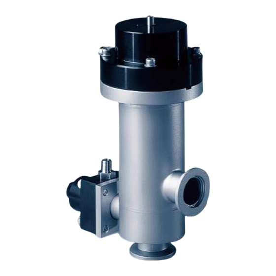
Chapter One: General Information Introduction Chapter One: General Information Introduction The Two-Stage Valve (see Figure 1) consists of a main isolation valve and a soft start bypass valve, all within a single valve body. Both valves are pneumatically operated bellows-sealed vacuum valves of stainless steel construction. -
Page 15: Chapter Two: Servicing An Hps Products Two-Stage Valve
Chapter Two: Servicing an HPS Products Two-Stage Valve Chapter Two: Servicing an HPS Products Two-Stage Valve Vacuum components must be kept free of both particulate contamination and of all foreign materials which would have a significant vapor pressure. Before repairing the vacuum valve, prepare a clean work station in a dust-free area. -
Page 16: Disassembly And Inspection Of Internal Assembly
Chapter Two: Servicing an HPS Products Two-Stage Valve Disassembly and Inspection of Internal Assembly To replace the actuator cap seal and the bonnet seal, sit the O-ring in the groove. Remove the nosepiece O-ring only if a new replacement is available. - Page 17 Disassembly and Inspection of Internal Assembly Chapter Two: Servicing an HPS Products Two-Stage Valve 2-Insert the assembly into the gear puller. Do not touch the bellows with the claws of the puller or any hard object. Bellows with the slightest damage must be replaced. A spanner must be placed on the nosepiece to prevent rotation.
-
Page 18: Disassembly Of The Bypass Valve
Chapter Two: Servicing an HPS Products Two-Stage Valve Disassembly of the bypass valve 9-To disassemble the upper stem guide assembly, 1) remove the two 6-32 x 0.25 pan head screws, 2) remove the seal retainer, 3) remove the stem seal. Inspect for wear. The bearing is press fit into the stem guide and should not be removed. -
Page 19: Disassembly And Inspection Of The Bypass Valve
Disassembly and Inspection of the Bypass Valve Chapter Two: Servicing an HPS Products Two-Stage Valve Disassembly and Inspection of the Bypass Valve 1-To further disassemble the bypass internal (see Figure 5), unscrew the piston from the bellows assembly. 2-Inspect the piston U-cup for excessive wear.
Need help?
Do you have a question about the HPS and is the answer not in the manual?
Questions and answers