Sign In
Upload
Download
Table of Contents
Contents
Add to my manuals
Delete from my manuals
Share
URL of this page:
HTML Link:
Bookmark this page
Add
Manual will be automatically added to "My Manuals"
Print this page
×
Bookmark added
×
Added to my manuals
Manuals
Brands
MKS Manuals
Control Unit
T3B Series
Supplement manual
MKS T3B Series Supplement Manual
With rs-232 interface
Hide thumbs
1
2
3
4
Table Of Contents
5
6
7
8
9
10
11
12
13
14
15
16
17
18
19
20
21
22
23
24
25
26
27
28
29
30
31
32
33
34
35
36
37
38
39
40
41
42
43
44
45
46
47
48
49
50
51
52
53
54
55
56
57
58
59
page
of
59
Go
/
59
Contents
Table of Contents
Bookmarks
Table of Contents
English
Table of Contents
Valve Safety Information
Symbols Used in this Instruction Manual
Symbols Found on the Unit
Safety Procedures and Precautions
Table 1: Definition of Symbols Found on the Unit
Tabelle 2: Bedeutung der am Gerät Angebrachten Symbole
Tableau 3: Définition des Symboles Sur L'unité
Tabla 4: Definición de Los Símbolos Hallados en la Unidad
Chapter One: Remote RS-232 Operation
RS-232 Protocol
Special Commands Supported (Version 01.04.00 and Newer)
Table 5: Message Syntax
Setup Messages
Table 6: RS-232 Setup Messages
Table 7: Sensor Range Values
Chamber Pump Speed
Setpoint Messages
Table 8: Setpoint Messages
(Code Version 01.04.08 or Newer)
Control Messages
Table 9: RS-232 Control Messages
Slow Pump Introduction
Slow Pump Behavior
Activation of Slow Pump
Valve.informational Messages
Informational Messages
Table 10: RS-232 Informational Messages
Chapter Two: RS-232 Message Summary
German
Sicherheitshinweise für das Ventil
In dieser Betriebsanleitung Vorkommende Symbole
Erklärung der am Gerät Angebrachten Symbole
Sicherheitsvorschriften und Vorsichtsmaßnahmen
French
Informations de Sécurité Relatives Au Manomètre
Symboles Utilisés Dans Ce Manuel D'utilisation
Symboles Figurant Sur L'unité
Mesures de Sécurité Et Précautions
Spanish
Medidas de Seguridad del Manómetro
Símbolos Usados en Este Manual de Instrucciones
Símbolos Hallados en la Unidad
Procedimientos y Precauciones de Seguridad
Advertisement
Quick Links
1
Table of Contents
2
Chapter One: Remote Rs-232 Operation
3
Rs-232 Protocol
4
Table 6: Rs-232 Setup Messages
5
Table 9: Rs-232 Control Messages
Download this manual
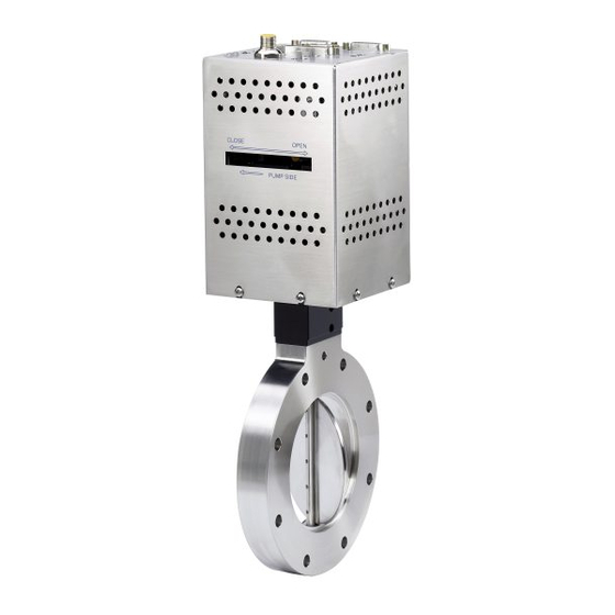
MKS Type T3B and T3P Valves
With RS-232 Interface
Supplement
2 Tech Drive, Suite 201
Andover, MA 01810-2449
Main: 978.975.2350
134414-P1
www.mksinst.com
RS-232 Interface
Rev 00G
Table of
Contents
Previous
Page
Next
Page
1
2
3
4
5
Advertisement
Table of Contents
Need help?
Do you have a question about the T3B Series and is the answer not in the manual?
Ask a question
Questions and answers
Related Manuals for MKS T3B Series
Control Unit MKS T3PIA Instruction Manual
Pendulum valve with analog/ttl interface (70 pages)
Control Unit MKS T3BIA Supplement Manual
With rs-232 interface (59 pages)
Control Unit MKS T3BIB Supplement Manual
With rs-232 interface (59 pages)
Control Unit MKS 356 Micro-Ion Plus Series Instruction Manual
Vacuum gauge module (76 pages)
Control Unit MKS 390 Series Instruction Manual
Granville-phillips series 390 micro-ion atm, four-sensor combination vacuum gauge module with rs-485 interface and analog output (100 pages)
Control Unit MKS 253B-2-2-2 Instruction Manual
253b series throttling valve (54 pages)
Control Unit mks HPQ2-IP Manual
(48 pages)
Control Unit MKS AX Series Manual
Universal display and control units for analogue input signals (24 pages)
Control Unit MKS SENTRY 1510A Installation & Operation Manual
Air flow control valve (56 pages)
Control Unit MKS 275 Series Instruction Manual
Mini-convectron module with rs-485 and dual process relays (55 pages)
Control Unit MKS Mini-Convectron 275 Series Instruction Manual
Vacuum gauge module with nonlinear analog outputs and process control relays (64 pages)
Control Unit MKS Granville-Phillips 274 Series Instruction Manual
Ionization gauges (30 pages)
Control Unit MKS 248A Manual
(35 pages)
Control Unit MKS HPS Square Body LoPro Series Operation And Maintenance Manual
Bellows sealed poppet valves (52 pages)
Control Unit MKS HPS Service Manual
Two-stage valve (21 pages)
Control Unit MKS Series 275 MiniConvectron Quick Start Manual
The granvillephillips series 275 miniconvectron vacuum gauge modules with nonlinear analog output and process control relays (2 pages)
This manual is also suitable for:
T3p series
T3bia
T3pia
T3bib
T3pib
Table of Contents
Save PDF
Print
Rename the bookmark
Delete bookmark?
Delete from my manuals?
Login
Sign In
OR
Sign in with Facebook
Sign in with Google
Upload manual
Upload from disk
Upload from URL


Need help?
Do you have a question about the T3B Series and is the answer not in the manual?
Questions and answers