Table of Contents
Advertisement
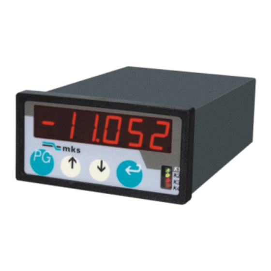
Universelle Anzeige- und
Überwachungsgeräte für
Analoge Größen
• Eingänge 0 -1V, 0-10V, 0-100V
0 - 20 mA, 4 - 20 mA
( Pt 100 gegen Bestellangabe )
• 2 einstellbare Grenzwerte und
"Null" - Ausgang
• Einstellbare Mittelwertbildung
• Frei skalierbare Anzeige und
Nullpunktverschiebung
• Lineare und reziproke
Anzeigefunktion
• Programmierbare Linearisierungs-
Funktion
• Auch in Schutzart IP 65 lieferbar
Serie AX
Universal Display and
Control Units for Analogue
Input Signals
• Inputs 0 - 1V, 0 - 10V, 0 - 100V
• 2 presets and additional
• Selectable Average Calculation
• Free Scaling of Display and
• Linear and Reciprocal
• Programmable Linearisation
• Protection clars IP65 available
0 - 20 mA, 4 - 20 mA
( PT 100 version also available )
"Zero" Output
Zero Offset
Display Characteristic
Parameters.
AX34006E.doc / Oktober 03 / 24 Seiten
Advertisement
Table of Contents

Subscribe to Our Youtube Channel
Related Manuals for MKS AX Series


Summary of Contents for MKS AX Series
- Page 1 Serie AX Universelle Anzeige- und Universal Display and Überwachungsgeräte für Control Units for Analogue Analoge Größen Input Signals • Eingänge 0 -1V, 0-10V, 0-100V • Inputs 0 - 1V, 0 - 10V, 0 - 100V 0 - 20 mA, 4 - 20 mA 0 - 20 mA, 4 - 20 mA ( PT 100 version also available ) ( Pt 100 gegen Bestellangabe )
-
Page 2: Table Of Contents
MKS haftet jedoch nicht für eventuelle However, MKS will not be liable for Irrtümer und behält sich das Recht zu errors and reserves the right for technischen Änderungen ohne Ankün- changes at any time without notice. -
Page 3: Einführung
Einführung 1. Introduction Die Geräteserie AX ist geeignet zur Erfas- AX series is designed for measurement of sung analoger Eingangssignale ( nur DC ). analogue DC input signals. The following full Über die rückseitigen Klemmen stehen fol- scale ranges are accessible on the rear gende Messbereichs- Endwerte zur Verfü-... - Page 4 Die nachstehende Tabelle zeigt die mög- The subsequent table shows the possible lichen Kombinationen und die zugehörigen combinations Bestellangabe. Vorwahlen / Presets Ausgänge / Outputs Standard 3 x Transistor (Optokoppler) Tastatur- Eingabe 3x Transistor (Optocopler) Enter by Kepad Option VW 500 3 x Transistor (Optokoppler) Dekadenschalter frontseitig 3x Transistor (Optocopler)
- Page 5 Ausführungsbeispiele: Examples of models: AX 340 L2 N Standard AX 540 L2 N + VR 500 AX 540 L2 N + RL 500 AX 640 L2 N + VW 500...
-
Page 6: Blockschaltbild
230 VAC +24VDC in 115 VAC + 5V / 150mA +12V / 150mA 0 - 1 V Min ( K2 ) 0 - 10 V 0 - xxx V Optional Max ( K3 ) Analogue Out +/- 10V Optional 20 mA Analogue Out Zero ( K4 ) Out (K2, Min ) Out (K3, Max) - Page 7 Blockschaltbild Block Diagram Keypad disable D.P. Display 12Bit X 1/17 "COM+" + Sign Processor X 1/16 "Zero" K4 X 1/14 "Min" K2 OP. Mode X 1/15 "Max" K3 Scaling +/-10V X 1/11 Analogue Out +/-10V (Operand) X 1/10 Analogue Out GND X 1/13 Analogue Out 20mA X 1/12...
-
Page 8: Bedienung Der Tastatur
Bedienung der Tastatur 3. Keypad operation Die Tastatur besteht aus 4 Tasten The keypad uses four keys (Tastatur-Sperre siehe 14) (Keypad disable see 14) Die Programmierung beginnt mit Betä- To set parameters, touch „PRG“ first. The tigung der Taste „PRG“. Das Gerät zeigt unit will display „P00“... - Page 9 4.2 Bereich 0 - 10 V: 4.2 Range 0 - 10 V ( Ri = 250 KOhm ) ( Ri = 250 KOhm ) X 1 / 7 +/- 10 V X 1 / 3 4.3 Individueller Spannungsbereich 4.3 Individual Full Scale Range Um die volle Auflösung des DAC zu nutzen, For some applications it may be useful to kann es manchmal zweckmäßig sein, das...
-
Page 10: Skalierung Der Anzeige
Skalierung der Anzeige 5. Scaling procedure 5.1 Setzen Sie zuerst den Parameter P01 5.1 Select the desired input range and display (Betriebsart) auf den gewünschten Ein- mode by the mode register P01. gangsbereich bzw. Anzeigemodus. Bereich Vollaussteuerung Characteristic Bild P 01 Range Full Scale Characteristics... -
Page 11: Verschiebung Des
5.3 Mit Parameter P 07 können Sie an beliebi- 5.3 Register P07 allows to set a ger Stelle einen Dezimalpunkt zuschalten. decimal point at any position Display xxxxxx xxxxx.x xxxx.xx etc 5.4 Parameter P 30 erlaubt die Zuschaltung 5.4 Register P 30 selects the floating average einer fließenden Mittelwertsbildung. -
Page 12: Programmierbare
Programmierbare Linearisierung 7. Programmable Linearisation Eine Linearisierung kann über 10 frei wähl- You can linearise your display by selecting bare x / y - Koordinaten durchgeführt wer- 10 x / y coordinates within the measuring den. Das Gerät verbindet die Zwischen- range. - Page 13 Linearpotentiometer haben In their externe positions, lineare potentio- Endberei-chen Ungenauigkeiten. meters mostly are not accurate enough. Außerdem ergibt sich eine Also, by loading the Wiper with a measuring current, noulinearity comes up especially in Kurvenkrümmung durch die Be-lastung des Schleifers mit dem Meßstrom, was im the centre range and the measuring results are inaccurate.
-
Page 14: Eingabe Von Grenzwerten
Solche Funktionen sind besonders inter- Such functions may especially be interesting essant bei Geräten mit Analogausgang for units with analogue output (option AO). ( Option AO ) Analogue Analogue Anzeige, Analogausgang Display, Analogue Output P55 P56 V, mA Eingang / Input Eingabe von Grenzwerten 8. -
Page 15: Min/Max- Speicher
Display Output "Min" P12 = 1 Output "Max" Output "Min" P12 = 2 Output "Max" Wenn Ausgang „Min“ als Minimalwertüber- When using the „Min“ output as real wachung genutzt wird, kann mit Parameter Minimum control, register P29 provides a P29 eine Anlaufüberbrückung vorgege- start-up delay. -
Page 16: Frontseitige Tastenfunktionen
10. Frontseitige Tastenfunktionen 10. Additional key functions (P23-P25) (P23-P25) Neben normalen Eingabefunktion Beside the normal register setting functions, it may be desirable to have further functions können die frontseitigen Tasten attached with a front key (i.e. Reset). This is noch für Zusatzfunktionen herangezogen werden (z.B. -
Page 17: Parallelausgang
12. Parallel-Ausgang (Option) 12. Parallel Output (optional) Parameter P32 gestattet die Vorwahl des Register P32 selects the desired output gewünschten Ausgabeformates: code: P32 = 1 BCD- Code P32 = 2 Binary Code P32 = 3 : Gray Code Alle 20 Ausgangsleitungen sind opto-isoliert All of the 20 output lines are opto isolated und PNP-schaltend. -
Page 18: Serielle Schnittstelle
13. Die serielle Schnittstelle 13. The Serial interface ( Option RS 500 ) ( Option RS 500 ) 13.1 Konfiguration ( P93 ) 13.1 Configuration ( P 93 ) Entsprechend der Tabelle kann mit P93 Register P93 selects one of the following die Konfiguration bestimmmt werden. - Page 19 13.5 Ausgabeformat ( P 13 ) 13.5 Communication format ( P 13 ) P13 = 1 PC - Mode ( Protocoll ) P13 = 2 Terminal- Mode ( Printer ) Im PC- Mode müssen die gewünschten With PC mode, the PC must send the Daten vom PC angefragt werden.
- Page 20 − die frontseitige Tastatur − by pressing a key on the front ( siehe Abschnitt 10 ) ( see section 10 ) − den internen Timer P 14. Dieser ist − by using the internal timer register einstellbar von 0 sec ( keine auto- P 14.
-
Page 21: Tastatursperre
T+ T - 13 12 11 10 25 24 23 22 21 20 19 18 17 16 15 14 Computer RS 485 ( 4 wire ) 14. Tastatursperre 14. Keypad disable Wenn Parameter P00 auf „0“ gesetzt ist, When register P00 is set to „0“, the keys are accessible at any time. -
Page 22: Parameter-Liste
15. Parameter-Liste 15. Register list Function Range Tastatursperre ein / aus P 00 Enable / Disable Keypad Betriebsart P 01 1- 8 Operation mode Skalierungsfaktor P 02 01 - 999 999 Scaling factor Dezimalpunkt P 07 0 - 5 Decimal point Vorwahl 1 ( Min ) P 10 -99 999 - 999 999... -
Page 23: Parameter Für Optionen
16. Registers for options 16. Parameter für Optionen Function Range Serielles Protokoll PC/Printer P 13 ( Opt. RS500) Serial protocol select Serieller Timer P 14 0 - 500.00 sec ( Opt. RS500) Timer register for serial output Datenformat am Parallelausgang P 32 1 - 3 ( Opt. -
Page 24: Technische Daten
18. Technische Daten 18. Technical Data Versorgungspannung 115/230 VAC, 18-30 VDC Power Supply (optional 24VAC, 12VDC) Leistung: AC: 4 VA Consumption DC: 200 mA Hilfsspannung für Sensoren + 5 V / 150 mA Aux. Voltages for sensors 12 V / 150 mA Eingänge +/-1V, +/-10V, +/-XV, 0-20mA / 4-20mA Inputs...
Need help?
Do you have a question about the AX Series and is the answer not in the manual?
Questions and answers