Table of Contents
Advertisement
Quick Links
Advertisement
Table of Contents

Related Manuals for MKS Ophir IPM


Summary of Contents for MKS Ophir IPM
- Page 1 7Z07106 - REV 2 - 25/OCT/2022 User Manual OPHIR IPM – INDUSTRIAL POWER METER HIGH POWER INDUSTRIAL LASER MEASUREMENT POB 45021, HAR HOTZVIM 9145001 E-MAIL: SALES.OPHIR.USA@MKSINST.COM JERUSALEM, ISRAEL WWW.OPHIROPT.COM/PHOTONICS PHONE + 972-2-548 4444...
-
Page 2: Table Of Contents
USER MANUAL 7Z07106 - REV 2 - 25/OCT/2022 Table of Contents 1 Warranty & Safety Information ......................5 Safety Procedures and Precautions ................... 5 Symbols Used in This Instruction Manual ................... 5 2 Specifications ............................6 3 IPM Overview .............................10 Introduction ..........................10 Application options (all combinations of the options below are possible) .........11 3.2.1 Basic application ........................11... - Page 3 USER MANUAL 7Z07106 - REV 2 - 25/OCT/2022 4.2.6 Power Out Mini 7/8" Female Connector (IPM-COM-M) .............21 Assembly of the Shutter Unit onto the IPM sensor ..............22 5 Firmware Upgrade for IPM Sensor and IPM-COM ................23 Connections ..........................23 StarLab instructions ........................23 5.2.1 Preparations ........................23 5.2.2 Connecting to the IPM: ......................23 5.2.3 Performing firmware upgrade ....................24...
- Page 4 USER MANUAL 7Z07106 - REV 2 - 25/OCT/2022 8 Service Portal .............................52 Navigating to the Service Portal ....................52 Service Portal – Top Panes ......................52 Service Portal – Home Page .....................54 Service Portal – Settings Page ....................54 8.4.1 Go/No-Go Feature – Details ....................56 8.4.2 Flow Meter Settings –...
-
Page 5: Warranty & Safety Information
DO NOT SUBSTITUTE PARTS OR MODIFY INSTRUMENT Do not install substitute parts or perform any unauthorized modification to the instrument. Return the instrument to an MKS Calibration and Service Center for service and repair to ensure that all safety features are maintained. -
Page 6: Specifications
USER MANUAL 7Z07106 - REV 2 - 25/OCT/2022 2 Specifications This section contains COPIES of the spec sheets for each of the 3 units of the IPM system available at the time of publishing the User Manual. For the LATEST specifications, please check the Ophir website. INTRODUCTION •... - Page 7 USER MANUAL 7Z07106 - REV 2 - 25/OCT/2022 Part RS232 cable, M12 male 5-pin to D9 female, 1.8m (supplied with sensor) 7Z10532 Cables Power cable, M12 female 5-pin to flying leads, 1.5m (supplied with sensor) 7E01519 Interlock cable, M8 female 3-pin to flying leads, 1.5m (not supplied) 7E01513 Water Flow Meter cable, M8 male 6-pin to flying leads, 1.5m (not supplied) 7E01536...
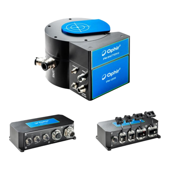
- Page 8 USER MANUAL 7Z07106 - REV 2 - 25/OCT/2022 IPM-SHUTTER10 Shutter Assembly for IPM-10KW For usage in a dirty industrial environment, the IPM-10KW can be fitted with an automated dust tight shutter assembly to protect the unit from dust and debris. The shutter unit has a built-in scatter shield and includes a field replaceable antireflection coated protective window.
- Page 9 USER MANUAL 7Z07106 - REV 2 - 25/OCT/2022 IPM Industrial High Power Sensor IPM-COM – IPM adapter for industrial protocols Modern automation systems integrate equipment from multiple vendors into a common Ethernet infrastructure. The IPM- COM is an industrial communication module enabling the integration of the IPM industrial sensor into Profinet or EtherNet/IP automation systems.
-
Page 10: Ipm Overview
7Z07106 - REV 2 - 25/OCT/2022 3 IPM Overview The Ophir IPM (Industrial Power Meter) is a family of products designed to offer laser power measurement solutions in a tough industrial environment. The products are designed to be rugged, dust proof and splash proof with an IP rating. -
Page 11: Application Options (All Combinations Of The Options Below Are Possible)
USER MANUAL 7Z07106 - REV 2 - 25/OCT/2022 • Water flow meter interface: A connector is provided to connect an external water flow meter (customer supplied) to monitor the flow rate of the cooling water; this can also be used to switch the interlock to disable the laser. -
Page 12: Interlock
USER MANUAL 7Z07106 - REV 2 - 25/OCT/2022 With additional IPM-SHUTTER10: 3.2.3 Interlock • If the sensor overheats due to insufficient cooling water flow, an internal temperature sensor can be used to trigger the interlock mechanism. This output can be connected to the laser interlock system in order to turn off the laser automatically and prevent damage to the sensor. -
Page 13: Water Flow Meter Interface
USER MANUAL 7Z07106 - REV 2 - 25/OCT/2022 3.2.4 Water Flow Meter interface • Can be used for precise water flow measurement and control of the laser interlock • Ophir does not provide the flow meter, the customer will purchase and connect it to their water cooling system •... -
Page 14: Full System Setup
USER MANUAL 7Z07106 - REV 2 - 25/OCT/2022 Using the IPM sensor with EtherNet/IP, Profinet industrial protocols 3.2.6 Full System Setup Full System Setup 14 | IPM USER MANUAL... -
Page 15: Details Of Connectors
USER MANUAL 7Z07106 - REV 2 - 25/OCT/2022 4 Details of connectors 4.1 IPM Sensor – Connectors & Pinouts This section provides details of the connectors on the IPM sensor. These are the connectors and indicators provided on the IPM sensor: •... -
Page 16: Power / Ipm-Com Connector
USER MANUAL 7Z07106 - REV 2 - 25/OCT/2022 Features: • M12 Female 5-pin connector • Used to connect the sensor by RS232 to a host PC or PLC. • Intended for customers using direct RS232 communications • Also required by customers using IPM-COM for sensor firmware updates •... -
Page 17: Interlock Connector
USER MANUAL 7Z07106 - REV 2 - 25/OCT/2022 4.1.3 Interlock connector This connector is used to provide an interlock interface to the laser Pinout: Function Color COM (Common) Brown NO (Normally Open) Blue NC (Normally Closed) Black Note 1: "Color" refers to wire coloring on optional interlock cable Features: •... -
Page 18: Ipm-Com - Connectors & Pinouts
USER MANUAL 7Z07106 - REV 2 - 25/OCT/2022 Recommended vendors of Water Flow Meters: See GEMS - www.gemssensors.com See GPI - www.gpimeters.com See OMEGA – www.omega.com 4.2 IPM-COM – Connectors & Pinouts This section provides details of the connectors provided on the IPM-COM and IPM-COM-M units. These are the connectors and indicators provided on the IPM-COM unit: •... -
Page 19: Sensor / Rs232 Connector (Both Types)
USER MANUAL 7Z07106 - REV 2 - 25/OCT/2022 4.2.1 Sensor / RS232 connector (both types) This connector is used to connect to the IPM sensor, and for RS232 communications with a host PC for firmware upgrades of the IPM-COM. Connector Pinout: Function +24v TxD (output) -
Page 20: Aida Power Connector
USER MANUAL 7Z07106 - REV 2 - 25/OCT/2022 4.2.3 AIDA Power Connector This connector is used to provide +24v power to the IPM-COM Connector Pinout: Function Color +24v input Brown Black +24v actuator (not connected to IPM-COM, connected to second connector only) Blue Actuator GND (not connected to IPM-COM, connected to second connector only) Grey... -
Page 21: Power In Mini 7/8" Male Connector (Ipm-Com-M)
USER MANUAL 7Z07106 - REV 2 - 25/OCT/2022 4.2.5 Power In Mini 7/8" Male Connector (IPM-COM-M) This connector is the power input connector, providing +24v power to the IPM-COM-M unit (for clarity, this connector and the next are shown in a different format to the others) Connector Pinout: Function Color... -
Page 22: Assembly Of The Shutter Unit Onto The Ipm Sensor
USER MANUAL 7Z07106 - REV 2 - 25/OCT/2022 4.3 Assembly of the Shutter Unit onto the IPM sensor The customer can assemble the IPM-SHUTTER10 unit on the sensor by themselves. Below is an illustriation of how this is done The IPM SHUTTER unit contains a built-in scatter shield which effects the calibration NOTE of the sensor. -
Page 23: Firmware Upgrade For Ipm Sensor And Ipm-Com
USER MANUAL 7Z07106 - REV 2 - 25/OCT/2022 5 Firmware Upgrade for IPM Sensor and IPM-COM This section provides basic information about firmare upgrades for the IPM sensor unit and IPM-COM unit. Firmware upgrades for both units are supported by Ophir StarLab software. For full details, see the StarLab User Manual. -
Page 24: Performing Firmware Upgrade
USER MANUAL 7Z07106 - REV 2 - 25/OCT/2022 5.2.3 Performing firmware upgrade Select the Device Tools icon: Select the "Upgrade" button: Select the firmware file (StarLab will automatically show the latest file it can find in the correct location as shown below). - Page 25 USER MANUAL 7Z07106 - REV 2 - 25/OCT/2022 Firmware upgrade of the IPM-COM can be performed in the same way as the IPM sensor. 25 | IPM USER MANUAL...
-
Page 26: Rs232 Commands
USER MANUAL 7Z07106 - REV 2 - 25/OCT/2022 6 RS232 Commands The IPM Sensor is intended to be used in one of three ways: • Via an industrial protocol (such as Profinet, EtherNet/IP) – using the IPM-COM • Via the "Service Portal" (see below) – using the IPM-COM •... - Page 27 USER MANUAL 7Z07106 - REV 2 - 25/OCT/2022 Measurement Commands: Measurement Mode – Selects Power or Energy Measurement Mode $MM 2|3 Send Power Send Energy Energy Status Energy Flag Energy Threshold Energy Ready All Measurement information – returns all measurement data available on a single line Get Event –...
-
Page 28: Details Of Rs232 Commands For Ipm Sensor
USER MANUAL 7Z07106 - REV 2 - 25/OCT/2022 Send Max Scale – return full scale measurement presently chosen scale Limits for Go/No-Go feature Get status bit values for Go/No-Go feature 6.2 Details of RS232 Commands for IPM Sensor These rules apply for all the RS232 Commands available for the sensor. Any exceptions will be listed separately below. - Page 29 USER MANUAL 7Z07106 - REV 2 - 25/OCT/2022 $VE – Firmware Version Returns a two-letter code identifying the sensor and the firmware version running in the sensor Example: $VE[CR] -> *IM1.14[CR] (IPM sensor) $VE[CR] -> *DM1.14[CR] (IPM sensor, in downloader mode during firmware upgrade) $VE[CR] ->...
-
Page 30: Temperature Commands
USER MANUAL 7Z07106 - REV 2 - 25/OCT/2022 6.2.2 Temperature Commands $RT – Body Temperature Queries sensor's body temperature and max allowed body temperature. Example: $RT[CR] -> *28.9 60[CR] (returns body temperature 28.9 degC, max defined body temperature 60 degC) Notes: With adequate water cooling, the body temperature will normally be close to constant even if the sensor is measuring high power. -
Page 31: Measurement Commands
USER MANUAL 7Z07106 - REV 2 - 25/OCT/2022 Notes: Zeroing should be performed with the sensor covered or with the laser switched off. For best performance, zero the sensor after it has reached a steady temperature and after the cooling water temperature and flow are stable. - Page 32 USER MANUAL 7Z07106 - REV 2 - 25/OCT/2022 $SP – Send Power: Returns the latest power measurement from the sensor, when it becomes available. The same measurement is never returned twice. Measurements can be obtained at a maximum rate of 15 times per second (therefore there may be a delay of up to 66ms before receiving a reply, not including command latency).
- Page 33 USER MANUAL 7Z07106 - REV 2 - 25/OCT/2022 measurement already present, and if the response is “1”, the old measurement should be cleared by sending the $SE command before continuing. See sub-section “Notes on Measurement Energy in Support Software” below. Example: $EF[CR] ->...
- Page 34 USER MANUAL 7Z07106 - REV 2 - 25/OCT/2022 • When the $EF command returns "1", send the $SE command once. This should return the energy value of the latest pulse measured by the sensor. Log this measurement for the application. •...
- Page 35 USER MANUAL 7Z07106 - REV 2 - 25/OCT/2022 The timestamp is a 32-bit value representing time in microseconds since the time stamp was initiated (at power up, or after a $TZ command). The timestamp is delivered as an 8 character value in HEX. After reaching the value of 3,999,999,999 microseconds (~66.667 minutes), the timestamp clocks back around to zero.
-
Page 36: Control Commands
USER MANUAL 7Z07106 - REV 2 - 25/OCT/2022 $CS 1[CR] -> *STOPPED[CR] (returns "STOPPED" after each $CS 1 command even if CS mode was already stopped) $CS[CR] -> *1[CR] (query, can be sent only when NOT in CS mode; sending while in CS mode will stop CS mode) Continuous Send - Power Mode: When measuring power, data is sent at the measurement rate of the device (15Hz). - Page 37 USER MANUAL 7Z07106 - REV 2 - 25/OCT/2022 $HC – Sensor ("Head") Configuration Saves present sensor settings as startup default settings. Settings affected are Startup power or energy scale and wavelength index ("S" parameter; see $WN, $WI); Calibration data ("C" parameter; see $CQ command); and Response time tweak ("R"...
-
Page 38: Water Flow Rate & Interlock Commands
USER MANUAL 7Z07106 - REV 2 - 25/OCT/2022 $WI 2[CR] -> *[CR] (selects second laser option, "NIRS") $WI[CR] -> *2[CR] (query, second laser option selected, "NIRS") $WI 5[CR] -> ?PARAM ERROR[CR] (bad parameter, there is no laser option 5) 6.2.6 Water Flow Rate &... -
Page 39: Calibration Commands
USER MANUAL 7Z07106 - REV 2 - 25/OCT/2022 Sending parameter 1 and a value sets the lower limit (water flow rate must not drop below this limit). Sending parameter 2 and a value sets the upper limit (water flow rate must not be higher than this limit). The lower limit must be smaller than the upper limit. -
Page 40: Misc. Commands
USER MANUAL 7Z07106 - REV 2 - 25/OCT/2022 value 10000. Setting a value above 1.0000 causes the reading to be increased, setting a value below 1.0000 causes the reading to be decreased. Ophir does NOT recommend that users adjust calibration values on WARNING their own. - Page 41 USER MANUAL 7Z07106 - REV 2 - 25/OCT/2022 $MX Max/Min Limits Returns the maximum and minimum limits on several sensor parameters. Each parameter has its own value. 1 -> Multiplier value as defined for Industrial Protocol (default value=1, meaning mW / mJ values are returned) 2 ->...
- Page 42 USER MANUAL 7Z07106 - REV 2 - 25/OCT/2022 $SX – Send Max Scale Returns the maximum full scale measurement on the present chosen scale, either power or energy. See $AR. Example: $SX[CR] -> *6.000E3[CR] (top scale chosen is 6000, 6kW power scale, index 1, second scale) $SX[CR] ->...
-
Page 43: Summary Of Rs232 Commands For Ipm-Com
USER MANUAL 7Z07106 - REV 2 - 25/OCT/2022 $GG -> *0 0 [0 = outside limits for set 1, 0 = outside limits for set 2] $GG -> *0 1 [0 = outside limits for set 1, 1 = inside limits for set 2] $GG ->... - Page 44 USER MANUAL 7Z07106 - REV 2 - 25/OCT/2022 $NA – Network Protocol This command queries the Industrial Network Protocol being used by the IPM-COM unit. It returns a code number 0, 1 or 2. Example: $NA[CR] -> *0[CR] (no network connected) $NA[CR] ->...
-
Page 45: Industrial Protocol Registers
USER MANUAL 7Z07106 - REV 2 - 25/OCT/2022 7 Industrial Protocol Registers This section describes the registers used to implement the industrial protocols supported by the IPM-COM unit. 7.1 Introduction The IPM-COM contains read and write registers used to control the sensor and to read back data from the sensor. - Page 46 USER MANUAL 7Z07106 - REV 2 - 25/OCT/2022 0x0002 0x0002 Selects POWER Mode $MM 2 & saves as default automatically 0x0002 0x0003 Selects ENERGY Mode $MM 3 & saves as default automatically 0x0003 index (1..5) Select laser option index, 1 to 5 $WI &...
- Page 47 USER MANUAL 7Z07106 - REV 2 - 25/OCT/2022 0x0013 value Set Max Flow Rate $FL 2 In ml/min, used for status bits 0x0014 value Set Flow Rate Control 1=just measure flow 2=update register error bits 3=control interlock 0x0020 value Set max body temperature $RT 1, in degC, used for interlock (cannot exceed factory defined maximum)
- Page 48 USER MANUAL 7Z07106 - REV 2 - 25/OCT/2022 0x0060 0x0001 Max power in present selected scale 0x0060 0x0002 Max energy in present selected scale Returns 0 if not in Energy Mode 0x0060 0x0003 Multiplier for power/energy values 1 by default 0x0060 0x0004 Index of present measurement scale...
-
Page 49: Read Register - Data
USER MANUAL 7Z07106 - REV 2 - 25/OCT/2022 7.3 Read Register – Data: The Read Register contains 30 bytes as defailed below. The first 4 bytes contain the Status Register. 7.4 Status Register This section describes the 32-bit Status Register. This register can alternatively be treated like 4 bytes, or two 16-bit values. -
Page 50: Read Register - Data (32 Bytes)
USER MANUAL 7Z07106 - REV 2 - 25/OCT/2022 Energy mode: either energy above 110% of defined full-scale energy, or power was saturated during energy integration). Spare IPM-COM unit specific bits: Sensor not connected Status 0 = sensor present, 1 = sensor not present ERROR - undefined command or bad Error Also used for bad command such as Cover... - Page 51 USER MANUAL 7Z07106 - REV 2 - 25/OCT/2022 Water flow rate mL/min $FV. Returns zero if water flow meter not enabled using S/W commands. Sensor body temperature degC/10 Returns 354 for 35.4 degC (see $RT) Sensor disk temperature degC/10 Returns 354 for 35.4 degC (see $GT) Command Replies General field for command...
-
Page 52: Service Portal
USER MANUAL 7Z07106 - REV 2 - 25/OCT/2022 8 Service Portal This section describes the "Service Portal" provided as a series of webpages within the IPM-COM unit. The Service Portal provides a method for a technician to configure the sensor without the need to connect directly to the sensor via RS232, while keeping the interface to the sensor via the industrial protocol (Profinet, EtherNet/IP) as simple as possible. - Page 53 USER MANUAL 7Z07106 - REV 2 - 25/OCT/2022 • Sensor: Corresponds to status register bit 22, "Sensor not connected": Green=sensor connected, Red=sensor not connected. • Interlock: Corresponds to status register bit 12, "Interlock status": Green=interlock inactive (all ok), Red=interlock active (i.e. an error in laser system, for example sensor is too hot; flow rate too low or too high.
-
Page 54: Service Portal - Home Page
USER MANUAL 7Z07106 - REV 2 - 25/OCT/2022 8.3 Service Portal – Home Page The home page is the "top" page of the Service Portal. It contains basic information about the sensor and IPM- COM unit, such as serial numbers and firmware versions. Service Portal –... - Page 55 USER MANUAL 7Z07106 - REV 2 - 25/OCT/2022 Service Portal – Wrong Password screen: Service Portal - Settings Page: The settings screen contains the following controls: • Measurement Mode – toggles the setting between power mode and energy mode 55 | IPM USER MANUAL...
-
Page 56: Go/No-Go Feature - Details
USER MANUAL 7Z07106 - REV 2 - 25/OCT/2022 • Scale – toggles between the power scales (W, in power mode) or energy scales (J, in energy mode). In power mode, an extra option is "Auto" mode which sets the sensor into Autorange mode where it selects its own power scale based on the incident power level •... -
Page 57: Flow Meter Settings - Details
USER MANUAL 7Z07106 - REV 2 - 25/OCT/2022 The two sets of limits are independent of each other and could overlap. For example, suppose the laser system under normal use should have 7000W +/- 500W. The first set of limits ("Limits 1") would be set to 6500 W min and 7500 W max. -
Page 58: Service Portal - Tcp/Ip Page
USER MANUAL 7Z07106 - REV 2 - 25/OCT/2022 the Status Register bits, and also control the interlock if the flow rate is below min flow rate or above max flow rate. Note that setting the flow meter active (mode options 2 or 3) when no flow meter is attached to the sensor will cause the software to detect a flow rate of zero. -
Page 59: Service Portal - Measurements Page
USER MANUAL 7Z07106 - REV 2 - 25/OCT/2022 The IP Address, Subnet Mask, Gateway and mode can be changed inside this page. Changing the mode to DHCP allows the network to allocate a dynamic IP Address to the IPM-COM. By default a static IP Address is used. -
Page 60: Service Portal - Limits Page
USER MANUAL 7Z07106 - REV 2 - 25/OCT/2022 Service Portal – Measurements Page - Energy: Power: Displays the present power on the sensor in Watts. Energy: In Energy Mode only, displays the most recently completed energy measurement, and the "Ready" status (displays "Ready"... - Page 61 USER MANUAL 7Z07106 - REV 2 - 25/OCT/2022 Service Portal – Limits Page: Maximum power: Maximum power supported by the sensor, in Watts (factory default). Minimum power: Minimum power supported by the sensor, in Watts (factory default). Maximum energy: Maximum energy supported by the sensor, in Watts (factory default). Minimum energy: Minimum energy supported by the sensor, in Watts (factory default).
-
Page 62: Ipm-Com Web Utility
USER MANUAL 7Z07106 - REV 2 - 25/OCT/2022 9 IPM-COM WEB UTILITY The IPM-COM WEB UTILITY is a PC App provided by Ophir, available on the Ophir Website. The PC App provides the following functionality: • Searching IPM-COM units connected to the network •... -
Page 63: Searching And Connecting To Ipm-Com Device The First Time
USER MANUAL 7Z07106 - REV 2 - 25/OCT/2022 9.2 Searching and Connecting to IPM-COM Device the First Time 1. Search for IPM-COM devices on the network by clicking on the "Search" button. A list of devices located on the network will be shown in the table in the lower part of the window. If no devices are located, try selecting another Network interface device to search, and press "Search"... - Page 64 USER MANUAL 7Z07106 - REV 2 - 25/OCT/2022 3. The first time a new IPM-COM unit from the factory is powered up, it will have a default IP Address. For EtherNet/IP devices, the default IP Address is 10.0.0.2. For PROFINET devices, the default IP Address is 0.0.0.0.
-
Page 65: Changing The Ip Address
USER MANUAL 7Z07106 - REV 2 - 25/OCT/2022 6. Choose "OK"; an edit box allowing a change of the IP Address will appear at the top of the window. If the selected device was not "Unknown" (if it already had an IP Address that was compatible with the network IP Address), the "Change"... - Page 66 USER MANUAL 7Z07106 - REV 2 - 25/OCT/2022 3. If the IP Address is not a valid IP Address for the network and the device is displayed as "Unknown", see how to proceed in the section above (use "right-click" to enable a change to the IP Address). 4.
-
Page 67: Upgrading The Service Portal Version
USER MANUAL 7Z07106 - REV 2 - 25/OCT/2022 9.4 Upgrading the Service Portal Version 1. If the IPM-COM contains an old version of the Service Portal software, it can be upgraded by clicking on the "Upgrade" button at the top of the window. If the current version is the SAME as the version contained within the PC App, a message will appear: 2. -
Page 68: Opening The Service Portal
USER MANUAL 7Z07106 - REV 2 - 25/OCT/2022 5. After the upgrade, the files will be verified, and the progress will be shown in the "Verifying" progress bar. 6. At the end of a successful upgrade process, a message will appear to confirm the upgrade was successful: 9.5 Opening the Service Portal 1. - Page 69 All rights reserved. No part of this work may be reproduced or transmitted in any form or by any means, electronic or mechanical, including photocopying and recording, or by any information storage or retrieval system, except as may be expressly permitted in writing by MKS Instruments, Inc. mksinst™ is a trademark of MKS Instruments, Inc.
Need help?
Do you have a question about the Ophir IPM and is the answer not in the manual?
Questions and answers