
Related Manuals for MKS Ophir Helios Plus


Summary of Contents for MKS Ophir Helios Plus
- Page 1 Helios, Helios Plus Helios, Helios Plus High Power Industrial Laser Measurement User Manual Ophir Optronics Solutions Ltd.
-
Page 2: Table Of Contents
Table of Contents ..................................1 Table of Contents ............................2 About this Manual ............................3 How the Document is Organized ......................3 Chapter 1 – Helios Operating Principle ......................4 Overview ............................... 4 Physical Principle ............................4 Example of Use: Laser Welder in a Robotic Cell ................... 4 Chapter 2 –... -
Page 3: About This Manual
Chapter 9 – PC Application ........................26 Chapter 10 – Getting Started With EtherNet/IP ................... 33 Chapter 11 – Getting Started With Profinet ....................36 Appendix 1 – Flow Chart & Timing Diagrams ..................... 38 Measurement Flow Chart ......................... 38 Power Measurement Timing Diagram .................... -
Page 4: Chapter 1 - Helios Operating Principle
Chapter 1 – Helios Operating Principle Overview The Helios sensor measures high power industrial lasers by measuring the energy of a short time exposure of the CW laser. The laser should be set to pulse from 0.1 to several seconds. The Helios measures the energy and exposure time of this sample of the power, and from this calculates the CW power. -
Page 5: Chapter 2 - Specifications
Chapter 2 – Specifications == Subject to change. Check our website for latest version spec: www.ophiropt.com/laser-measurement Short Exposure High Power Sensors with Industrial Communications Protocol Helios Plus P/N 7Z07100 / 7Z07101 (rev2 23-12-20) 50W to 12000W Features • No water cooling, up to 12000W •... - Page 6 == Subject to change. Check our website for latest version spec: www.ophiropt.com/laser-measurement Short Exposure High Power Sensors with Industrial Communications Protocol – P/N 7Z02768 / 7Z02789 (rev16 8-12-19) Helios 50W to 12000W Features • No water cooling, up to 12000W •...
-
Page 7: Chapter 3 - Setup
Chapter 3 – Setup There are four ways to interface with the Helios laser power meter: 1. Profinet 2. EtherNet/IP 3. RS232 commands (e.g., with HyperTerminal) 4. PC application The setup of Helios depends on the mode of operation. Profinet Setup •... - Page 8 Zoomed-In: • Integrate the power measurement into the customer software (controlled by the PLC) as fits their application and needs. • See Chapter 7 for more details on Profinet setup and read/write registers (called “submodules”). • Begin test measurements. • Integrate into production line routine.
-
Page 9: Ethernet/Ip Setup
EtherNet/IP Setup • Place the Helios where it will be convenient to measure the laser. • Connect 24 V DC to standard Profinet / EtherNet/IP jack. (Use Ophir Power Cable for Helios P/N 7Z10458A, see Chapter 6 “Connectors” for more details) •... -
Page 10: Rs232 Setup
• Choose the Helios device - it will be identified as “NETIC” or similar as shown above. • Click the “Configure” button, then “SetIP Address…”. Enter the new values of IP Address and Subnet Mask (usually 255.255.255.0) and click “OK”. After a few seconds, repeat “Search Devices” to check the IP settings are updated successfully. -
Page 11: Chapter 4 - Check Before Use
Chapter 4 – Check before Use Be sure to check the laser parameters before turning it on to ensure no damage to Helios. Specifically, the power, beam size, and exposure time must be within the specifications. (Use this calculator to easily find the power density from laser power and beam size.) Preliminary test Here’s a sample test to be sure everything is operating as it should:... -
Page 12: Chapter 5 - Mechanical Dimensions
Chapter 5 – Mechanical dimensions Cover closed (bottom): 200 x 100 x 84 mm (length by width by height) Cover open (top): 200 x 123 x 144 mm (length by width by height) Note the cover opens farther than the picture shows. When the cover is open at 90° as shown, the width is 112 mm. When the cover is open as far as possible, the width will be 123 mm. -
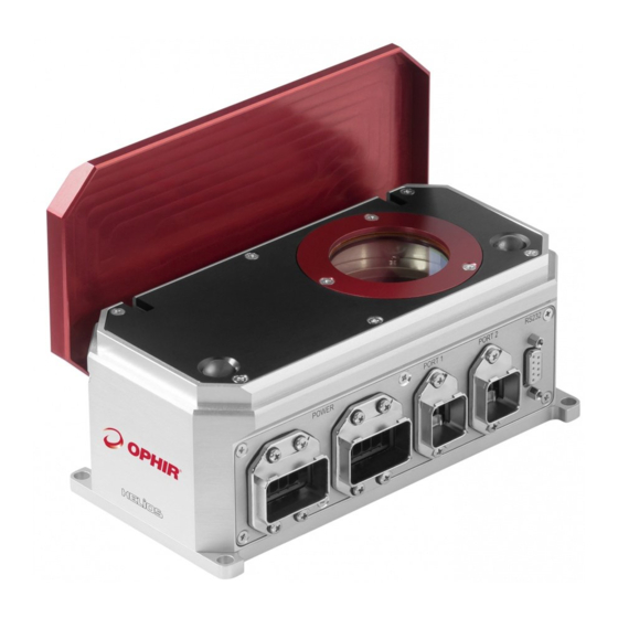
Page 13: Chapter 6 - Connectors
Chapter 6 – Connectors From left to right, the connectors above are: (1) Two power connectors, both 5-pin Han Push-Pull Power. (2) Two RJ45 Profinet / EtherNet/IP connectors, both Han Push-Pull RJ45 PN (compatible with Ophir P/N 7E01298 / 7E01299 or Harting part 09 35 226 0401. Standard IP20 cables can also be used, but without a locking mechanism.) (3) One D9 connector for RS232 Power Connectors... -
Page 14: Rj45 Connectors
RJ45 Connectors The RJ45 sockets are Hirose (RJ45 connector), part TM21R5C88(50) and Harting (metal hood), part 09 35 002 0301. They are compatible with Ophir P/N 7E01298 (for Profinet) or Ophir P/N 7E01299 (for EtherNet/IP) or (for example) Harting part 09 35 226 0401, or Phoenix Contact part 1408972 Function [NC] [NC]... -
Page 15: Chapter 7 - Registers & Commands
Chapter 7 – Registers & Commands This chapter is relevant when using the Profinet or EtherNet/IP protocols. It describes the registers and data that can be read from the Helios, and the commands that can be sent to the Helios. LED indicators table There are seven LEDs for different status/error indications. -
Page 16: Status: 16-Bit Register
Status: 16-bit Register NOTE: In Big Endian mode, the UPPER (top) byte is output first (byte 1). In Little Endian mode, the bytes are swapped over and the LOWER byte is output first (byte 0). NOTE: In earlier versions of this manual the “Cover” was referred to as the “Shutter”. NOTE: Items displayed in red have been added in Helios firmware version 1.13, Sept. -
Page 17: Measurement Results & Information
Measurement Results & Information: Byte Register Units Length Read/Write 22-25 Latest power measurement 4 bytes Read μs 26-29 Latest irradiation time measurement 4 bytes Read 30-33 Latest energy measurement 4 bytes Read 34-37 Present power (* Note 3) 4 bytes Read 38-39 Temperature of Helios device... -
Page 18: Querying And Changing Laser Options
Send command “8” (= open cover) Check status register - 01 81 (01 = “open”; 81 = ack from cover command, ready to measure) Send command “0” (= clear ack bits) Check status register - 01 01 (01 = “open”; 01 = ready to measure) Send command “10”... -
Page 19: Analysis Of Example Data, Big Endian
The following sections show examples how to understand the data received from the Helios, for BIG and LITTLE Endian systems. NOTE: The examples give below do not mention laser options, the values reported by the Helios appear as zeroes. Analysis of Example Data, BIG Endian: First version Rev 1.00 22 Sep 2016... - Page 20 This example shows how the data will look with Big Endian format, for example when using Profinet. In this example, the data was obtained when the Helios was first powered up, before any measurements are taken. 11 02 - status 00 98 96 80 00 00 27 10 27 10 00 64 2E E0 00 64 00 3C 00 00 00 00 00 00 00 00 00 00 00 00 00 00 00 00 00 81 00 1E 00 01 00 00 27 10 00 00 00 00 00 00 00 00 00 00 00 00 00 00 00 00 00 00 - data The data can be analyzed by splitting it up into groups as defined above, Constants and Measurement Results.
-
Page 21: Analysis Of Example Data, Little Endian
negative, in which case it will be displayed as 2s-compliment, for example FF FF FF 27, Hex value 0xFFFFFF27, decimal -217 mW) 00 1E - temperature of Helios. Hex value 0x001E, decimal 30 degrees C 00 01 - current energy scale is index 0x0001 (10kJ scale) - other scales are 2 (1kJ scale) and 3 (100J scale) 00 00 27 10 - max energy in current scale (J). - Page 22 64 00 - min exposure time (ms). Hex value 0x0064, decimal 100 (ms) E0 2E - max power (W). Hex value 0x2EE0, decimal 12000 (W) or 12 kW 64 00 - min power (W). Hex value 0x0064, decimal 100 (W) 3C 00 - max allowed temperature of Helios.
-
Page 23: Chapter 8 - Rs232
Chapter 8 – RS232 General Information: 1. All commands are initiated by PC; Helios responds to them ONLY AFTER RECEIVING THE FINAL [CR] symbol 2. All communications with PC are in ASCII symbols – not binary values 3. All commands from PC begin with ‘$’ symbol 4. - Page 24 Save Head Configuration Settings: $HC S[CR] -> *[CR] {Saves the CURRENT SETTINGS of energy scale as the power-up defaults} Note: In order to change the power-up defaults, the following sequence is necessary: a. Set desired power scale using $WN command b.
- Page 25 $RT[CR] ->* <Internal temperature> <maximum allowed temperature>[CR] {This command sends the internal temperature of the power meter, in degrees Celsius, followed by the maximum allowed temperature, and terminated with [CR]. It can return measurements up to a maximum rate of 15 times per second. The integrator should use this to ensure that the Helios is left to cool down when the internal temperature reaches or exceeds the maximum allowed temperature.} Example:...
-
Page 26: Chapter 9 - Pc Application
Chapter 9 – PC Application Getting Started The PC application can be found in the Helios product page in the website. Copy the executable file to your local computer and run it (as an administrator) to install. Follow the steps in the installation wizard to complete. This is the initial screen. - Page 27 Use the “Wavelength” dropdown to select the desired wavelength range. In this example there are two available wavelength ranges, NIR (Near Infrared e.g. 1064nm) and B-G (Blue-Green region, ~450-550nm). Check the datasheet for your specific model for information about exact wavelength ranges supported. (Note: some of the following pictures are taken from a previous version of the PC Application, they are for general illustration only).
- Page 28 “Send.” Messages are returned (when applicable) on the right side of this button: “Instantaneous Power” can be selected to show the power of the laser at any given moment. This is not generally useful for accurate power reading, since the thermopile has a 2-3 second response time and a typical use-case of the Helios is for times shorter than this.
- Page 29 Click “Open Log File Folder” to open the directory in which the log files are generated: Note, the log file is found inside a folder named by the serial number of Helios device used. This folder is found within the Helios installation directory. First version Rev 1.00 22 Sep 2016...
- Page 30 Three types of files are created here: The CSV file is a list of all the measurements taken, including: 1. “FullDataLog.csv” – This file includes all the data from the latest use of the PC application. It includes power, energy, and exposure of each laser shot, as well as instantaneous power, temperature, Profinet status, and pulse status (wait / ready / integrating) 2.
- Page 31 Select Help > About to find this screen: It contains: • Software name • Company name • Software version • Device name and serial number • Firmware version • MAC Address The “Help” menu also contains an option for upgrading firmware as new versions are released. Cover Operation Initially, the cover should be closed.
- Page 32 After opening completely, the status changes to “OPEN” and the button will now close the cover, if pressed again. The “ERROR!” message means the cover is neither completely open nor closed, and has timed out (and so isn’t considered “in motion” anymore). This usually indicates something blocking the cover. If this is not the issue, contact Ophir for further assistance.
-
Page 33: Chapter 10 - Getting Started With Ethernet/Ip
Chapter 10 – Getting Started With EtherNet/IP This chapter describes how to control the Helios using the EtherNet/IP protocol, and how to read data from the Helios. Examples are shown using a PC based tool called “EIP_TOOL”, available on the internet from Molex/ODVA. The principles described in this chapter should be applicable to any EtherNet/IP tools running on a PLC or a PC. - Page 34 Click on the check box to the left of the word “Attribute” to open the entry window. When all the values are entered correctly, click on “Send Request” button to perform the data transfer. Data Example: These examples are given using the tool mentioned above. To read data from the Helios, use the settings shown in the screen shot below: 0x0E, 4, 101, 3, and click on the “Send Request”...
- Page 35 Settings used to write command (0x8 = Open Cover) to the Helios: Analyzing the data from the Helios: An example of data read from the Helios is shown below. This first example shows data when the Helios has close to zero incident power on the sensor, and no energy pulse has been measured recently.
-
Page 36: Chapter 11 - Getting Started With Profinet
Chapter 11 – Getting Started With Profinet This chapter describes how to control the Helios using the Profinet protocol, and how to read data from the Helios. Examples are shown using the tool “ProfinetCommander” to provide examples. The tool “ProfinetCommander” presents the data from the Helios like this: The status register (2 bytes) and results (multiple bytes) are presented in the “Input”... - Page 37 Type the data (in HEX) into the window and click on “OK” to send the data to the Helios. Check the status and ResultsConst again to see updated status information from the Helios. First version Rev 1.00 22 Sep 2016 Helios User Manual...
-
Page 38: Appendix 1 - Flow Chart & Timing Diagrams
Appendix 1 – Flow Chart & Timing Diagrams Measurement Flow Chart First version Rev 1.00 22 Sep 2016 Helios User Manual... -
Page 39: Power Measurement Timing Diagram
Power Measurement Timing Diagram Shutter Timing Diagram Changes in version 1.07-1 (30-Sep-2020) 1. Registers: Added new command 0xFE to clear Exposure Time Error bit in status register (f/w 1.12) 2. Removed words “supplied with helios” regarding ‘Import the EDS file’ above 3.
Need help?
Do you have a question about the Ophir Helios Plus and is the answer not in the manual?
Questions and answers