Table of Contents
Advertisement
Advertisement
Table of Contents
Troubleshooting

Related Manuals for MKS Ophir LaserStar


Summary of Contents for MKS Ophir LaserStar
- Page 1 Artisan Technology Group is your source for q new and certified-used/pre-owned equipmen • FAST SHIPPING AND SERVICE CENTER REPAIRS WE BUY USED EQUIPME DELIVERY Experienced engineers and technicians on staff Sell your excess, und at our full-service, in-house repair center We also offer credit fo •...
- Page 2 LaserStar LaserStar Laser Power/Energy Meter User Manual Ophir Optronics Solutions Ltd. www.ophiropt.com/photonics...
-
Page 3: Table Of Contents
Table of Contents Chapter 1 Introduction: How to Use This Manual ..........3 Chapter 2 Quick Reference ..................4 Getting Started....................4 Thermal Heads....................6 Photodiode Heads.................... 9 Pyroelectric Heads ..................11 Chapter 3 The Laserstar Display Unit ..............15 General Description.................. - Page 4 Chapter 7 Operation with RP heads................ 64 General Description..................64 Principle of Operation..................64 Advantages of the RP ..................66 Temporal Pulse Shape .................. 67 Measuring Repetitively Pulsed Lasers with the RP ......... 67 Setup for RP - Rapid Pulse measurement..........68 Choosing Default Pulse Width Setting ............
-
Page 5: Chapter 1 Introduction: How To Use This Manual
Chapter 1 Introduction: How to Use This Manual The Ophir Laserstar is a microprocessor-based Laser Power/Energy Meter providing a broad range of measurements, displays, and data handling options. It operates with thermopile, pyroelectric and photodiode heads, and uses smart connector technology. -
Page 6: Chapter 2 Quick Reference
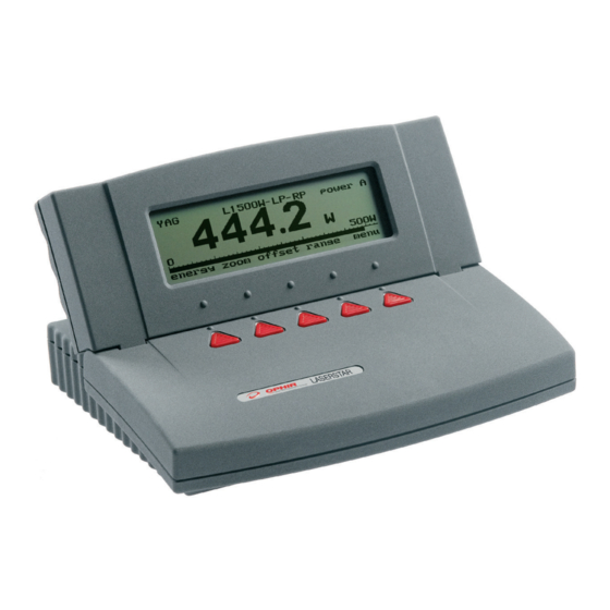
Chapter 2 Quick Reference 2.1 Getting Started The Laserstar is equipped with "soft keys." That is, the functions of the keys change as indicated by the legend above each key. (See Figure 2). To connect head to the Laserstar Display Insert the 15 pin D type connector of the measuring head cable into the socket marked "Head Input"... - Page 7 off/on/backlight 12.34 energy zoom offset range menu Figure 2 LaserStar Top View To switch the Laserstar on: 1. Flick the toggle switch on the right side of the rear panel up. Note that there are three positions, down is off, the center is on and the upper position is on with backlight on.
-
Page 8: Thermal Heads
To set line frequency: 1. Disconnect the head and switch off then on again. "Head Disconnected" will appear. 2. Select “line frequency”. 3. Press "value" to change to the correct line frequency. 4. Press "save" and the line frequency will be saved. To zero instrument: Disconnect the head, turn off then on again. - Page 9 To choose power or energy measurement: To go from the main power measurement screen to the energy measurement screen, press "energy". To go from the energy measurement screen to power measurement, press “power”. 2.2.2 Setting and Saving the Startup Configuration Turn on the Laserstar with the head disconnected and press “value”...
- Page 10 2.2.3 Power or Single Shot Energy Measurement Warning: Do not exceed maximum head limits for power, energy, power density and energy density as listed in tables 6 and 7 in section 11.2 Otherwise, there is a risk of damaging the absorber. To use the Laserstar to measure Laser power: Verify that the display shows "power"...
-
Page 11: Photodiode Heads
To use the Laserstar to measure Laser energy: Verify that the display shows "energy" in the upper right hand side of the display. If the display shows "power" and units of W, mW etc. then press "energy" to switch to the energy measurement mode. The energy mode is manual ranging. - Page 12 2.3.2 Selecting Chosen Wavelengths From the power measurement mode, press "menu" and select "wavelength". Press "go". Select the wavelength you wish to change and press "go. Using the up/down buttons, change to the desired wavelength. Now press exit. Repeat steps 2 and 3 for other wavelengths desired. Up to 6 wavelengths may be selected.
-
Page 13: Pyroelectric Heads
To subtract background and set current reading to zero: From the main power measurement screen press "offset". Press "offset" again to cancel. See Section 5.4.5 for full details. To use the Laserstar to fine-tune Laser power: From the main power measurement screen press the menu button then select "tune". - Page 14 2.4.3 To set type of laser being used From main measurement screen, press "laser" until the correct laser type or wavelength is displayed. 2.4.4 Setting Startup Configuration With the head disconnected, switch on the Laserstar and press the “value” button to select the type of startup screen you wish. (Note that this choice is stored in the Laserstar and not the head so will be operative for all heads).
- Page 15 2.4.5 Energy or Average Power Measurement Warning: Do not exceed maximum head limits for power, energy, power density and energy density as listed in tables 6 and 7 in section 11.2 Head Specifications. Otherwise, there is a risk of damaging the absorber. With the pyroelectric head, you have been supplied a test slide with the same coating as on your pyroelectric detector.
- Page 16 2.4.5.4 To measure Total Energy Exposure: Press the menu button and select “exposure”. Press “go”. Select parameters then press “start”. Press “start” again. The Laserstar will start summing laser energy exposure. If you wish to stop before the chosen period, press ”stop”. If you wish to reset the reading to zero before another reading, press "reset".
-
Page 17: Chapter 3 The Laserstar Display Unit
Chapter 3 The Laserstar Display Unit 3.1 General Description The model Laserstar laser power/energy meter represents a new level of sophistication, sensitivity, compactness and accuracy, coupled with ease of operation. It can operate with thermal, pyroelectric and photodiode heads. It has smart connector technology. -
Page 18: Smart Connectors And Multi Head Operation
3.2 Smart Connectors and Multi head Operation The Laserstar display is versatile and can operate with either thermal, pyroelectric or photodiode type laser measuring heads. The head configuration and calibration information is stored in an EEROM in the head connector plug. This means that when the head is plugged in, the Laserstar automatically identifies the head type, calibration and configuration. - Page 19 3.3.2 Key Functions The Laserstar has certain conventions as to the meaning of standard keystrokes and these are as follows: Highlighted item : The highlighted item is the item presently active. <--,--> These buttons move to the next active item leftwards, rightwards.
-
Page 20: Power Up And Shut Down
3.4 Power up and Shut Down To turn the Laserstar on: Flick the toggle switch on the left side of the rear panel up. The unit will switch on, and the display will appear. If no head is connected, a display showing "Head Disconnected"... - Page 21 3.5.1 Startup Screen The Laserstar can operate in the standard power/energy measurement screen or can display the information in specialized forms: an attenuation screen, a power/energy density screen or a screen with limits. Set the screen to the type you want the instrument to start up in and press select to go to the next option (For more details on the various screen options, see section 4.6).
- Page 22 3.5.6 Zero Adjustments In the Laserstar, all adjustments, including zeroing internal circuits, are done from the software. This ensures simple and accurate realignment. It is recommended to re- zero the Laserstar every 2 months for best performance. The simple zeroing procedure follows.
-
Page 23: Hardware Functions
3.6 Hardware Functions 3.6.1 Backlight The backlight illuminates the display from the rear and is operated by the same switch as turns the instrument on and off (See Figure 4). The Laserstar backlight consumes considerably less power than competing instruments and therefore it can operate from the battery even when the charger is not plugged in. - Page 24 When the battery is low, "BAT" flashes on and off and if the audio warning is activated, a warning beep will sound every 5 seconds. When this happens, the charger should be plugged in. In order to charge the batteries again, the charger should be left plugged in with the unit switched off for 14 hours.
-
Page 25: Chapter 4 Operation With Thermopile Absorber Heads
Chapter 4 Operation with Thermopile Absorber Heads Warning: Before using the head for power or energy measurement, check that your laser power, energy and energy density do not exceed the head ratings. See tables 6 and 7 in section 11.2 Head Specifications. If the head is a water-cooled type, ensure that the cooling water is flowing at an adequate rate;... -
Page 26: Selecting Settings From The Laserstar Screen
4.2 Selecting Settings from the Laserstar Screen The Laserstar can be set to various chosen settings while operating. In addition, it can be set so that it will be in the desired configuration when turned on the next time. 4.2.1 To Set Type of Laser being Used Thermopile heads have somewhat different absorption at different wavelengths. -
Page 27: Startup And Configuration Of Defaults
4.2.3 To choose Power or Energy Measurement The Laserstar thermopile heads can measure both power and single shot energy. See sections 4.4 and 4.5 for details. To change from power to energy measurement or vice versa do the following: 1. To go from the main power measurement screen power to energy measurement, press "energy". -
Page 28: Power Measurement
6. Select “Average over:” and select the period you wish to average power readings over. This feature is especially useful for lasers with nonsteady output. See section 4.4.2.4 for details. 7. Select “Power Range:” using the arrow keys. Now choose the manual power range you wish to be the default or autorange. - Page 29 4.4.2 Additional Power Measurement Features The following section describes additional Laserstar functions in power mode in addition to the basic power measurement mode described above. 4.4.2.1 Zoom The Zoom function causes the scale to expand the present scale fivefold. Thus, if the full scale of the bargraph is 20 watts, and your reading is 15 watts, pressing “zoom”...
- Page 30 4.4.2.3 Tune (see Figure 5) The Tune function, an exclusive Ophir feature, makes adjusting your laser to its maximum power easier than ever before. Unlike a bargraph or mechanical meter, this display shows graphically what came before as well as the current reading and the trend.
- Page 31 23.45W 27.73W 1min setup +50% Figure 5 Power Tune Screen 4.4.2.3.3 Using the Audio Tune Function The Laserstar has an exclusive audio tune facility. The instrument can generate a rising or falling audio tone to indicate higher or lower power. To engage the audio feature, simply choose “Audio: on”...
- Page 32 To use the Laserstar to display average: 1. From the main power screen, press the menu button and select “config”. 2. Press “go” and select “Average over”.. Use the value button to select the average period you want or select “NONE" if you do not want to average. 3.
- Page 33 24.50W Normalization 1.021 24.00W laser range exit reset Figure 7 Thermopile Normalize Screen 4.4.2.6 Power vs. Time Graph and Data Logging The Laserstar in datalog mode has the option of graphing the laser power against time and storing the data in up to 10 permanent storage files with up to 5,400 data points in each file.
- Page 34 Note: For data logging, the instrument has to be in a manual power range. If it is not, a message will occur. Warning: Pressing “reset" will erase all previously stored data and start recording new data. 4. If you press the “stats” button, the graphical display will be replaced by a statistical summary of the data gathered till now.
- Page 35 FILE CONTROL Temp: 5400 Free Space: 54000 select save delete view Figure 9 File Control Screen 2. When the screen is entered, the data in the latest power graph will be stored temporarily in register “Temp”. Press “select” to select the permanent register you wish to use for storing the data and press “save”.
-
Page 36: Energy Measurement
Energy measurement RS232 GPIB Max real time data logging rate >30Hz >1500Hz Onboard data logging rate >200Hz >200Hz Data transfer from instrument to PC ~500points/s >1500points/s Max points stored onboard 59,400 59,400 (1): The above refers to the rate for logging every single point. Above that rate the instrument will sample points but not log every single point. - Page 37 4.5.2 Measurement To measure energy of a single pulse, set up as above and fire the laser. The display will go blank while the energy is being integrated. After 2-4 seconds, the correct energy will be displayed. When the Laserstar is ready to measure a new pulse, "ready" will appear on the screen and flash on and off.
- Page 38 Note (to users of 3A-P type heads): The 3A-P type head has special circuitry enabling it to trigger on energy pulses of very low energy. This is accomplished by a special photodiode trigger which alerts the Laserstar that a pulse has been received and to start integration. This allows the 3A-P to react to smaller pulses than would be measurable just by triggering on the rising thermal signal as in other heads.
- Page 39 Energy per pulse = Total Energy / Number of Pulses In both of the above methods, the pulse repetition rate must exceed 3Hz. Higher rates will generally give improved accuracy, but care should be taken not to exceed maximum power ratings. 4.5.5 Measuring Energy of Rapidly Repeating Pulses The standard Laserstar will only measure individual pulses every 5 seconds or so.
- Page 40 4.5.6 Energy Log and Data Storage (See Figure 11) The Laserstar has the option of displaying successive energy points in a scrolling vertical bargraph form. While measurements are being taken, the Laserstar will record data. Up to 59,400 points are stored See section 4.4.2.7.1 for more information on data storage and handling.
- Page 41 4.5.6.2 Turbo mode In regular data log mode above, you can only log every point at up to 180 points per sec. You can also not transmit to PC at higher rates than 180 Hz in regular data log mode. In order to log data or transmit it to PC at rates >1500Hz, you must be in turbo mode.
-
Page 42: Advanced Display Screens
4.6 Advanced Display Screens 4.6.1 Beam Splitter/Attenuator Screen If you have a measurement setup with a beam splitter or attenuator and wish to display the laser power or energy before the splitter or attenuator and not the actual value impinging on the measurement head the beam splitter function allows you to do this. - Page 43 Note 2: The attenuation value is stored in the Laserstar and not the head so if it is set, any head connected will come up with the value chosen. Note 3: If you have a dual channel Laserstar, the function will only work in single channel mode and the value set will be applied irrespective of which channel you use.
-
Page 44: Special Thermopile Heads
To set up the limits screen do as follows: 1. From the main power or energy screen press “menu”, select “advanced”, press “go”, select “limits” and press “go”. You are now in the limits screen. 2. Press “setup” and select the lower and upper limits as follows: With the up/down buttons select the lower limit digits, then with the arrow go to the exponent screen and with up/down select the exponent. - Page 45 The calibration of each measurement head is in the head plug so that heads and displays can be interchanged without losing calibration. It also allows user recalibration if desired. The BC20 has advanced circuitry with excellent sensitivity, signal to noise ratio, accuracy, and response time;...
-
Page 46: Chapter 5 Operation With Photodiode Type Heads
Chapter 5 Operation with Photodiode Type Heads Warning: Before using the head for power measurement, check that your laser power or energy and energy density does not exceed the head ratings. See table 6. 5.1 Photodiode Heads When a photon source, such as laser, is directed at one of the PD300 or 3A-IS series photodiode detectors, a current is created proportional to the light intensity and dependent on the wavelength. -
Page 47: Setting Up The Pd300 To Display The User's Chosen Wavelengths
FILTER OUT WAVE- PD300 PD300- PD300-UV 3A-IS WAVE- PD300- LENGTH LENGTH 250-350nm N.A. N.A. N.A. 800nm 20mW 400nm 30mW 30mW N.A. 1-1.3µm 30mW 633nm 20mW 20mW 1.4µm 25mW 670nm 13mW 13mW 1.5µm 15mW 800nm 10mW 10mW 2.5mW 1.6µm 10mW 900mm 10mW 10mW 2.5mW... -
Page 48: Startup Defaults
From the power measurement mode with the bargraph display, press the menu button located on the right and select “wavelength”. Press “go”. 2. Press “select” to select the first wavelength desired. Press “go”. 3. Change to the wavelength desired using the up and down buttons. If you desire to permanently save the new value press “save”. -
Page 49: Selecting Settings From The Laserstar Screen
5.4 Selecting Settings from the Laserstar Screen The Laserstar can conveniently be set to various chosen parameters from the screen. In addition these settings can be saved as startup defaults so the head will be in the desired configuration when turned on. 5.4.1 To Set to the Laser Wavelength Being Used Photodiode heads have a different sensitivity at different wavelengths. - Page 50 dBm - The Laserstar allows the measurement to be made in units of dBm that is a logarithmic scale. dBm units are defined as: 10 x log (reading in mW) At 1mW the reading will be 0 dBm, at 100mW it will be 20 dBm etc. To choose auto, manual or dBm range, follow these steps: 1.
- Page 51 To choose the filter setting: 1. From the main measurement screen press the menu button and then “go”. 2. If you wish to work with filter installed, press "change" until display says "filter is in". Be sure to install removable filter on detector head. 3.
- Page 52 When "offset" is engaged, the legend is highlighted. To cancel, press "offset" again. If the "offset" is engaged, and you wish to subtract a new value of the background, press "offset" twice. The first press will cancel the old value, and the second will activate a new value.
-
Page 53: Special Photodiode Heads
In order to measure very low powers do as follows: 1. Press “menu” and select “configure”. Choose the appropriate value you want to average over and save it and then exit. 2. Now block the power source you wish to measure, wait for a few measurement periods and press “offset”... - Page 54 Note: Because the BB heads are spectrally flat, wavelength selection is disabled. Other than that, operation is the same as other PD300 type heads. 5.5.2 PD300-CIE Photometer Head The PD300-CIE head has a spectral response similar to that of the human eye and can therefore make measurements in eye response units of Lux.
-
Page 55: Chapter 6 Operation With Pyroelectric Heads
Chapter 6 Operation with Pyroelectric Heads Warning: Before using the head for power or energy measurement, check that your laser power, energy or energy density do not exceed the head ratings as listed in tables 6 and 7 with the head specifications. Otherwise, there is a risk of damaging the absorber. - Page 56 PE50-BB energy 22.69 AVE: 10.00Hz Trig max: 50us power laser range menu Figure 14 Pyroelectric Energy Screen 6.2.1 Setting up the head to display the user's chosen wavelengths (Metallic Type Only) The absorption of the detector coating varies somewhat with wavelength. The correction curve for the absorber is stored in the head EEROM.
- Page 57 6.2.2 Setup of Laser Pulse Length and Pulses/Sample 6.2.2.1 Laser Pulse Length As was mentioned before, the Ophir pyroelectric heads can measure long as well as short pulses. In order to do this, the user must indicate to the Laserstar if the laser pulses are going to be in the long or short pulse regime (BB models only have the long pulse setting and measure all pulse lengths on this setting In that case “N/A”...
-
Page 58: Startup And Configuration Of Defaults
To set up for averaging over a number of pulses: 1. From the main measurement screen, press the menu button and select “configuration”. Press “go”. 2. Now select “Average over:” Now press "value" until the time period you wish to average over is displayed. -
Page 59: Energy, Power Or Exposure Measurement
To set the Laserstar startup mode and to save the chosen Laserstar configuration: 1. With the head disconnected, turn on the Laserstar. Press “value” to select the startup screen you wish to startup with as default and press “save”. 2. Connect the head and switch on the Laserstar. From the main measurement screen, press the menu button located on the right side. - Page 60 Note: To measure pyroelectric energies properly, it is important that the head is not grounded to the optical bench. Make sure that the head is isolated electrically from the ground. The PE head has been supplied with an insulating mounting post for this purpose.
- Page 61 3. Press exit to return to the measurement screen and save before exit if you want this to be the default range. 4. Press the menu button and select “configuration”. Press “go”. Select “Max Pulse Length” and set to the correct value for your laser. (See section 6.2.2.1 for further details).
- Page 62 6.4.1.3 Power Measurement 1. Make sure the instrument is in the power measurement mode indicated by the legend “power” in the top right of the screen and the units of mW, W, etc. If it is in energy measurement mode with units of mJ, µJ etc., then press the “power” soft key or alternatively, press the menu button and then the left "power"...
- Page 63 PE50-BBH exposure 224.7 00: 00: 49.3 172P setup reset start stop exit Figure 15 Exposure Screen 4. Press “start” again. The Laserstar will start summing laser energy exposure. When you wish to stop measuring, press "stop" or wait for the “time-out" selected in the setup screen.
-
Page 64: Measuring Repeating Pulses Of High Energy
24.50mJ Normalization 1.021 24.00mJ 30mJ apply laser range exit Figure 16 Pyroelectric Normalize Screen 6.5 Measuring Repeating Pulses of High Energy Because of their construction, pyroelectric heads are restricted in the energy density they can withstand, particularly for short pulses on the order of nanoseconds. If the energy density of your laser exceeds the rating of the pyroelectric absorber, there are several options available. -
Page 65: Energy Log
6.6 Energy Log This is the same as for thermal heads, except you do not have to wait for "reset". See sections 4.5.6. and 4.4.2.7.1. Note: For Pyroelectric heads logging energy the only setup option is ‘sample rate’. The user can choose the number of pulses he wishes to log - from ‘every pulse’ to ‘1 out of 1000’... -
Page 66: Chapter 7 Operation With Rp Heads
Chapter 7 Operation with RP heads Note: It is highly recommended to use the Customize function every time you work with a new laser type or setup. See section 7.10 below 7.1 General Description The exclusive Ophir RP type heads represents a unique way to accurately measure the energy of high energy repetitively pulsed lasers, while at the same time measuring average power, pulse shape, standard deviation, average energy, missing pulses and jitter. - Page 67 BNC connector to fast oscilloscope for temporal pulse shape Si photodiode Removable filter Incoming laser beam Scattered light Volume absorber Figure 17 Schematic Diagram of RP Head The RP photodiode and its associated circuitry give a signal proportional to the energy of arriving pulses.
-
Page 68: Advantages Of The Rp
A removable filter is provided in front of the photodiode to increase the dynamic range of energies measurable by the RP. If the energy per pulse of the laser is within the highest range, the 10x reduction filter is inserted so as to prevent detector saturation. The thermopile detector also has a built-in heater resistor that allows calibration to be performed by the electrical substitution method. -
Page 69: Temporal Pulse Shape
High Duty Cycle Unlike pyroelectric heads, the RP is able to measure the pulse energy of lasers whose pulse width is a large duty factor, i.e. the laser is on most of the time. This means that you can measure for instance a diode laser pulsing at 3Hz with 100ms pulse width where the duty cycle is over 30%. -
Page 70: Setup For Rp - Rapid Pulse Measurement
<800 30A-P-RP filter: out 22.69 10.00Hz Trig 50us 100mJ power laser >3Hz range menu Figure 18 RP Energy Screen 7.6 Setup for RP - Rapid Pulse measurement Your RP is capable of measuring rapidly pulsing laser pulses of any energy, from fractions of a millijoule to 10 Joules or higher. - Page 71 3. Absolute or Relative Mode The next choice is the operation mode “op mode:”. This can be “absolute” or “relative”. The absolute/relative function determines whether the energy displayed will be absolute or relative. Ordinarily, “absolute” will be selected. In this mode, the RP will calculate the actual pulse energy of each pulse based on the average power, as explained in section 7.2, “Principle of Operation”.
- Page 72 7. Stabilize (This function is connected with energy logging. See section 0 for further details). As explained above in paragraph 4, the RP is unable to measure the absolute energy of the laser pulses during the first few seconds of operation since the average power measurement has not yet stabilized and the RP needs this value in order to calculate the absolute energy.
-
Page 73: Choosing Default Pulse Width Setting
9. Laser Pulse Width The RP is able to measure lasers with a wide range of pulse widths from nanoseconds or below to hundreds of ms. In order to operate properly, the RP must be set up for the laser pulse width. This sets up the integration time during which the laser pulse energy is measured. -
Page 74: Configuration For Power And Single Shot Energy
Maximum Laser Repetition Rate for Given Pulse Width Setting Maximum Pulse Width Setting (ms) 0.01 1000 100000 10000 1000 Graph 1 Maximum Laser Repetition Rate for Given Pulse Width Setting 7.8 Configuration for Power and Single Shot Energy As part of its equipment to measure the energy per pulse of repetitively pulsing lasers, the RP contains a complete Ophir thermal power/energy head. -
Page 75: Zeroing
In the following section, we explain the various functions: 1. Startup: Choose whether you want the start up default of the RP will be energy or power measurement. 2. Laser: Choose the laser wavelength. (This can be chosen from other menus as well). -
Page 76: Data Logging
The customize function allows you at the push of a button to set the gain to an optimum value for the laser parameters you are measuring now. It is recommended to use this function and the user can always return to the factory default if desired. To customize the gain settings: 1. - Page 77 7.11.3 To use the RP for graphical display of energy: 1. Make sure that the RP is in the correct energy measurement range. 2. From the main measurement screen, press “menu” and select “data log”. Press “go”. Press “setup” to set up measurement parameters for head and sample rate. 2.1 If you have more than one head attached, choose the head you wish for data logging.
- Page 78 7.11.4 Stabilization and recording of initial pulses As discussed in section 7.6 paragraph 7, The RP allows you to record the absolute energy of the first pulses of a laser’s operation even though the average power is not yet stabilized. When logging energy pulses, the RP logs the photodiode output from the first pulse.
- Page 79 menu/rp config/go and select “Missing Pulses Detection”. Using the “value” key, choose <40Hz or >40Hz depending on your laser pulse rate. If you want to save this setting as the startup default, press “save” before exiting this screen. The RP will now record “missing” instead of the pulse value in the data log screen when a pulse is missing.
-
Page 80: Chapter 8 Operation With The Dual Channel Laserstar
Chapter 8 Operation with the Dual Channel Laserstar If you have the dual head version of the Laserstar, you can measure with two heads at the same time, either independently or in combination, measuring the ratio or difference between them. 8.1 Operation with One Head Plugged in Only When only one head is plugged into the dual channel Laserstar, in either channel, it operates the same as would a single channel Laserstar. - Page 81 3. Press “value” to select “BOTH” so both heads are active. 4. Now press “select” to select “CHANNEL A” and press value to select if you want the head to be in power or energy mode. Now press “select” again to select “CHANNEL B”...
-
Page 82: Chapter 9 Circuit Description
Chapter 9 Circuit Description The Laserstar has three circuit boards: an analog processor, a digital processor and a power supply. Analog Processor The signal from the detector head enters the analog processor board and passes through EMI protection components to a differential transimpedance preamplifier. From there it is further amplified by a programmable gain voltage amplifier and passes to a dual slope integrating analog to digital (A/D) converter. - Page 83 The digital processor is also responsible for controlling the basic analog processor, the fast analog processor, reading the keypad, driving the display and communicating via RS232. The CPU obtains calibration and capability data from a memory chip in the plug of the detector head and configures itself accordingly.
-
Page 84: Chapter 10 Calibration, Maintenance And Troubleshooting
Chapter 10 Calibration, Maintenance and Troubleshooting 10.1 Calibration of Thermopile or RP Heads 10.1.1 Absorber types and Method of Calibration of Ophir Power Meters 10.1.1.1 Types of Ophir Laser Absorbers Two types of absorber surface are used in Ophir thermal measuring heads: 1. - Page 85 2. Volume absorbers: P (pulse) type absorber The models with the P suffix, for use with pulsed lasers, have a special absorbing glass with an absorbance of 95 +2% over the operating range. Since the surface is a glass, its reflectivity does not change even if damaged or melted locally. HE/HE1 (high energy) absorber The HE and HE1 types have a particularly high damage threshold for pulsed and repetitively pulsed lasers of both the short and long pulse variety and are useful where...
- Page 86 Percent absorption Wavelength, µm BB therm. Percent absorption Wavelength, µm Graph 2. Absorption of Ophir Absorbers vs. Wavelength...
- Page 87 10.1.1.2 Method of Calibration The absorption of the various Ophir thermal absorbers can vary from disc to disc. Therefore, all Ophir absorbers are individually calibrated against NIST traceable standards. Ophir power/energy meters with the broadband or P type absorbers are individually calibrated by laser at several wavelengths against a NIST calibrated standard meter.
- Page 88 10.1.2.2 Total Accuracy of Calibration Since the instruments are calibrated against NIST standards, the accuracy is generally 1% at the power level at which the calibration has been performed. This accuracy has been verified by checking the scatter of the results when several instruments are calibrated against the same standard.
- Page 89 By accurately measuring the voltage and current applied, the calibration can be checked and if necessary, readjusted, taking into account the calibration factor. See Section 10.13 10.1.4.1 Guidelines for using the CAL resistor for calibration 1. Do not exceed the maximum electrical power stated in the table. MODEL POWER APROX.
- Page 90 10.1.4.2 Recalibration of Power using the Built in CAL Resistor If your thermal head has the Ophir CAL resistor then you have a traceable absolute calibration source available just by measuring the voltage and current into the CAL resistor and multiplying by the calibration factor provided by Ophir. Calibration instructions: 1.
- Page 91 Note 2: The unit retains for your information the current sensitivity of the head in A/W in engineering notation. The original value is retained at the factory. You should record the original setting so you can return to it if you wish. 10.1.4.3 Recalibration from a Known Source of Laser Power / Energy 1.
-
Page 92: Calibration Of Photodiode Type Heads
10.2 Calibration of Photodiode type Heads Photodiode detectors are inherently very linear but also have a large variation in sensitivity with wavelength. In addition, the Ophir model PD300 is equipped with both a built in filter and removable filter to allow measurement of higher powers without detector saturation. - Page 93 WAVE ERROR, FILTER OUT* LENGTH PD300 PD300-3W PD300- PD300- 3A-IS 200 - 250nm ±5% 250 - 360nm ±3% 360 - 400nm ±10% ±10% ±3% 400 - 950nm ±3% ±3% ±3% 950 - 1100nm ±5% ±5% ±5% ±5% 1100 - 1600nm ±5% 1600 -1800nm ±7%...
-
Page 94: Calibration Of Pyroelectric Type Heads
10.3 Calibration of Pyroelectric type Heads Three types of absorber surface are used in Ophir pyroelectric measuring heads: 1. Metallic type: The type with no suffix in the name have a partially reflective multilayer metallic coating which absorbs approximately 50% and whose absorption graph is shown in graph 2 below. - Page 95 10.3.1 Calibration The sensitivity of the various Ophir pyroelectric sensors can vary from one to another as well as with wavelengths. Therefore, Ophir pyroelectric detectors are individually calibrated against NIST traceable standards. In addition, the calibration is corrected in the Laserstar for different wavelengths. Ophir pyroelectric detectors are calibrated using a 1.06µm repetitively pulsed laser referenced to a NIST traceable thermal power meter.
- Page 96 The maximum error in measurement will be less than the sum of the above errors and in general will be considerably less. COATING TYPE BROADBAND METALLIC WAVELENGTH (ERROR) (ERROR) 190 - 350nm ±1% ±4% 400 - 800nm ±1% ±4% 1064nm 2 - 3µm ±2% ±8%...
-
Page 97: Error Messages
10.4 Error Messages The Laserstar displays various error messages when operated outside its normal range: Over range: When the power or energy being measured exceeds the range of the measurement scale being used, the over range message is displayed, but the reading still appears on the display. - Page 98 10.5.2 Thermal Heads, Energy Measurements Problem Cause/Remedy Instrument triggers on Increase threshold level; See Section. 4.5.3. background noise or sometimes fails to catch large pulse. Instrument does not show ready Increase threshold level; See Section 4.5.3. for a long while after a reading is made.
-
Page 99: Maintenance
10.5.4 Pyroelectric Heads Problem Cause/Remedy Instrument reads incorrectly or Possible electromagnetic interference from erratically, especially pulsing laser is causing misreading and/or sensitive scale. false triggering Instrument triggers even Check the following: without being exposed to laser 1. Head is mounted to stand using insulated pulses. - Page 100 Please follow the following steps in disc replacement. 1. Remove the screws from the front and rear flanges of the absorber head. 2. Remove the front flange and raise the rear flange, taking care not to tear the wires attached to the connectors. 3.
- Page 101 10.6.1.4 Battery Replacement If the Laserstar battery is defective and does not hold a charge, a replacement can be ordered from your agent. The new battery is installed as follows: 1. Turn the Laserstar display upside down and unscrew the 6 Phillips screws on the bottom panel of the Laserstar.
-
Page 102: Chapter 11 Laserstar Specifications
Chapter 11 Laserstar Specifications 11.1 Laserstar System/Display Specifications Input Specifications Thermal, Photodiode Input Ranges 15nA - 1.5mA full scale in 16 ranges A to D Sampling rate 15Hz A to D resolution 17 bits plus sign. (0.0009% resolution) Electrical accuracy ±0.25% ±... -
Page 103: Head Specifications
11.2 Head Specifications MAX POWER MAX AVG. POWER ABSORBER (WATTS) DENSITY TYPE PD300/UV/IR 300mW 50W/cm² PD300-3W 50W/cm² 3A-IS 200W/cm² Int Sph PD F100A-IS 100w 200W/cm² Int Sph Ther 200W/cm² 3A-P-CAL 50W/cm² 10A-P 50W/cm² 30A-P 50W/cm² 30(150)A-HE 30(150)W 1000W/cm² HE/HE1 20KW/cm² 20KW/cm²... - Page 104 Absorber Max Energy Density J/cm² Type Pulse Length 10ns 1µs 300µs HE/HE1 PE, Metallic PE, BB PE-DIF PE BB-DIF Table 7. Maximum Energy Densities for Various Absorbers (Single Pulse)
- Page 106 Artisan Technology Group is your source for q new and certified-used/pre-owned equipmen • FAST SHIPPING AND SERVICE CENTER REPAIRS WE BUY USED EQUIPME DELIVERY Experienced engineers and technicians on staff Sell your excess, und at our full-service, in-house repair center We also offer credit fo •...
Need help?
Do you have a question about the Ophir LaserStar and is the answer not in the manual?
Questions and answers