
Related Manuals for MKS Ophir Spiricon BeamWatch Standard


Summary of Contents for MKS Ophir Spiricon BeamWatch Standard
- Page 1 Ophir BeamWatch Standard ® User Notes Document No 50398-001 Rev F 02 Aug 2020 1 of 20...
- Page 2 Dear Ophir-Spiricon Customer, Thank you for your recent purchase of the BeamWatch system. At Ophir-Spiricon we strive to provide the highest level of leading edge photonic measurement technology and service possible. We hope that your experience with us is a pleasant one, and anticipate the relationship we build will serve your photonic measurement needs for years to come.
-
Page 3: How To Use This Guide
How to Use this Guide Symbol Notation Indicates general information that poses no risk. Indicates important information about the product with little or no risk. Indicates warning information. Failure to follow instruction may result in harm to the user or product damage. Document No 50398-001 Rev F 02 Aug 2020 3 of 20... -
Page 4: Optical Radiation Hazards
Safety While BeamWatch itself does not present the user with any safety hazards, this instrument is intended for use with laser systems. Therefore, the user should be protected from any hazards that the laser system may present. The greatest hazards associated with laser systems are damage to the eyes and skin due to laser radiation. -
Page 5: Chapter 1 Information
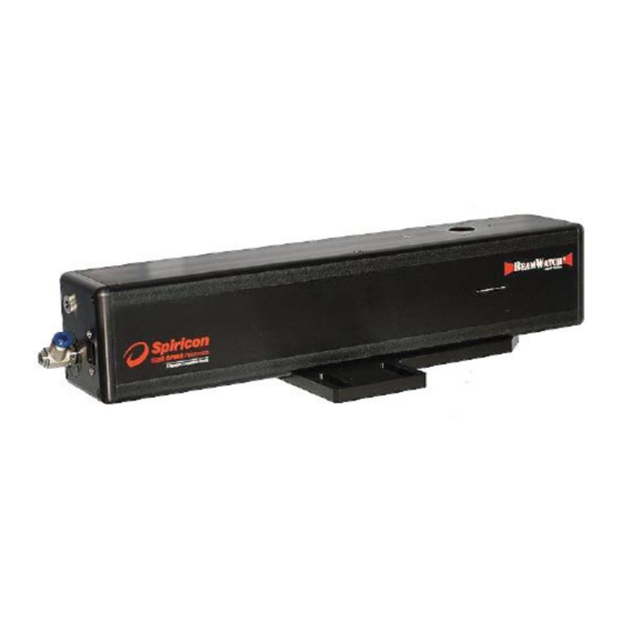
Chapter 1 Information Introduction BeamWatch is the laser industry’s first completely non-interfering beam monitoring system, which allows beam measurements without contacting the laser beam. Measurements are taken by imaging the Rayleigh scatter of the beam from the side using conventional cameras making BeamWatch ideal for measurements of high power lasers. Ophir- Spiricon has measured beams up to 100 kilowatts. - Page 6 1.1.1 Equipment BeamWatch Standard ¼” Polyurethane tubing 10ft Alignment tools Ethernet Cable 4.5m Gigabit to USB 3.0 Adapter Power Supply Cable Power Supply Adapter Kit User documentation: • Alignment tool User Notes • Calibration Certificate • Gig-E Camera User Notes Quick Start Guide •...
-
Page 7: Specifications
Optional Equipment Additional Optional equipment (Not Pictured) We recommend one or more of these additional products. BeamWatch rotation mount (SP90346) • Locking Ethernet cable (SP90394) • 10kW water cooled power sensor • 30kW water cooled power sensor • 100kW water circulated power sensor •... -
Page 8: Operating Limits
1.4 Operating Limits The graphics below are intended to give a visual indication of the recommended operating space for BeamWatch. If BeamWatch is operated outside of this space, it may be more difficult to see the curvature of the caustic or the beam may be large enough at the edges of the image that it is out of focus. - Page 9 Power density also plays a role in the operating space. The chart below shows the required power vs. focus spot size for a top hat beam. The equation to estimate the maximum spot size is derived from the power density equation: ��...
-
Page 10: Chapter 2 Hardware Configuration
Chapter 2 Hardware Configuration This chapter walks through how to setup and start using your BeamWatch. BeamWatch Standard Mounting The BeamWatch unit must be mounted to a stable surface where the laser can pass through the entrance and exit apertures unobstructed. - Page 11 After the BeamWatch is mounted, measure the distance from any desired reference point on the laser delivery head to the top face of the camera as shown right. This value is the Distance of the laser and must be entered into the software during setup (see section 4.4.2 in the BeamWatch Software User Guide).
- Page 12 2.1.3 Particulate Removal The industrial laser environment has high levels of particulates that must be removed from the camera FOV to obtain accurate results. With BeamWatch, this is accomplished by generating a laminar flow region at the camera FOV using a clean, dry gas source. Air, Nitrogen, or Argon is recommended.
-
Page 13: Laser Setup
Setup 2.1.5 Laser After installing and launching the software apply the purge gas at approximately 10 SLPM (35 PSI/2.5 BAR) and remove the dust caps from the BeamWatch STD unit. (Applying the gas before removing the dust caps helps prevent dust from entering the unit.) Apply the guide beam. - Page 14 Insert the alignment tool into the BeamWatch with the cutout side facing the camera as shown. Ensure the alignment tool is flush with the top. Start the BeamWatch software and enable the Crosshair located at the top of the 2D Beam Display window. Turn on the alignment beam and center it on the alignment tool by adjusting either the beam or the BeamWatch unit, with the beam perpendicular to the...
- Page 15 The beam is displayed in the BeamWatch software as an ellipse as shown in the images below. It may be necessary to adjust the Exposure and/or Frame Summing to bring the alignment beam to a viewable level. If the beam is centered on the crosshair as shown in the properly centered example, the beam is aligned. If the beam is not centered, adjust the angle the beam enters the BeamWatch.
- Page 16 2.1.7 Final Setup Steps Once the beam is aligned remove the alignment tool and switch from the guide beam to the high power beam. Enable live Playback from the Source Ribbon in the software. Adjust the gas level until a minimum amount of particulates can be seen.
- Page 17 2.1.8 Ending a Run After data collection has completed turn off the beam. Re-insert the dust caps on the unit. Turn off the purge gas. (Always turn the purge gas off after the dust caps have been re-inserted.) If needed disconnect the purge gas and electrical connections, and remove the unit from the working area.
-
Page 18: Chapter 3 Dimensions
Chapter 3 Dimensions Document No 50398-001 Rev F 02 Aug 2020 18 of 20... - Page 19 Notes: Document No 50398-001 Rev F 02 Aug 2020 19 of 20...
- Page 20 Notice © 2020 Ophir-Spiricon, LLC. All Rights Reserved. Ophir-Spiricon, LLC reserves the right to make improvements in the product described in this User Guide at any time and without notice. All rights to the product and any accompanying operator’s manuals are reserved. While every precaution has been taken in the preparation of this product, the publisher and author assume no responsibility for errors, omissions, or any loss of data because of said errors or omissions.
Need help?
Do you have a question about the Ophir Spiricon BeamWatch Standard and is the answer not in the manual?
Questions and answers