Sony DCR-TRV7 Service Manual
Digital video camera recorder
Hide thumbs
Also See for DCR-TRV7:
- Operating instructions manual (120 pages) ,
- Operating instructions manual (120 pages) ,
- Limited warranty (1 page)
Table of Contents
Advertisement
SERVICE MANUAL
D MECHANISM
NTSC : DCR-TRV7
PAL
: DCR-TRV7E
MICROFILM
DCR-TRV7/TRV7E
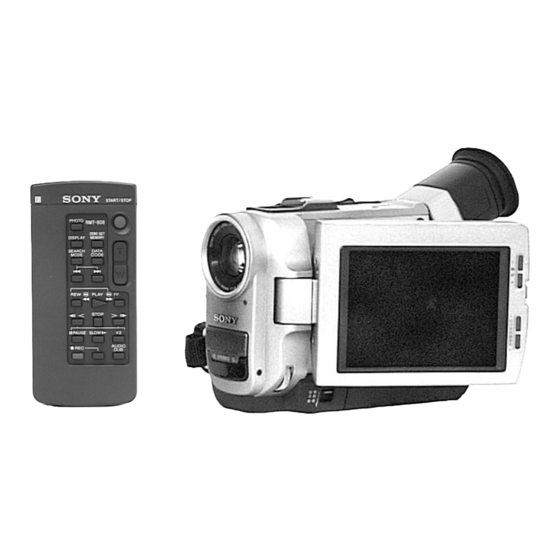
Photo : DCR-TRV7
: RMT-808
SPECIFICATIONS
DIGITAL VIDEO CAMERA RECORDER
— 1 —
RMT-808/809
US Model
Canadian Model
Tourist Model
AEP Model
UK Model
Tourist Model
For MECHANISM ADJUSTMENTS, refer to the
"DV MECHANICAL ADJUSTMENT MANUAL I"
(9-973-815-11).
— Continued on next page —
E Model
DCR-TRV7
E Model
DCR-TRV7E
Advertisement
Table of Contents

Related Manuals for Sony DCR-TRV7


Summary of Contents for Sony DCR-TRV7
- Page 1 Canadian Model E Model Tourist Model DCR-TRV7 AEP Model UK Model E Model Tourist Model DCR-TRV7E Photo : DCR-TRV7 D MECHANISM : RMT-808 NTSC : DCR-TRV7 For MECHANISM ADJUSTMENTS, refer to the : DCR-TRV7E “DV MECHANICAL ADJUSTMENT MANUAL I” (9-973-815-11). SPECIFICATIONS —...
- Page 2 THESE COMPONENTS WITH SONY PARTS WHOSE PART FONCTIONNEMENT. NE REMPLACER CES COMPOSANTS NUMBERS APPEAR AS SHOWN IN THIS MANUAL OR IN SUP- QUE PAR DES PIÈCES SONY DONT LES NUMÉROS SONT PLEMENTS PUBLISHED BY SONY. DONNÉS DANS CE MANUEL OU DANS LES SUPPLÉMENTS PUBLIÉS PAR SONY.
- Page 3 Supplied Accessories 1 Wireless Remote Commander (1) RMT-808 ; DCR-TRV7 / TRV7E : E, Tourist RMT-809 ; DCR-TRV7E : AEP, UK 2 NP-F530 battery pack (1) 3 AC power adaptor (1) AC-V316A ; DCR-TRV7 : Tourist DCR-TRV7E : E, Tourist AC-V326 ;...
-
Page 4: Service Note
SERVICE NOTE 1. POWER SUPPLY DURING REPAIRS In this unit, about 25 seconds after power is supplied (8.4V) to the battery terminal using the service power cord (J-6082-223-A), the power is shut off so that the unit cannot operate. This following two methods are available to prevent this. Take note of which to use during repairs. -
Page 5: Self-Diagnosis Function
SELF-DIAGNOSIS FUNCTION 1. Self-diagnosis Function 2. Self-diagnosis display When problems occur while the unit is operating, the self-diagnosis When problems occur while the unit is operating, the counter of the function starts working, and displays on the viewfinder what to do. viewfinder shows a 4-digit display consisting of an alphabet and This function consists of two display;... -
Page 6: Self-Diagnosis Code Table
4. Self-diagnosis Code Table Self-diagnosis Code Symptom/State Correction Block Detailed Function Code Remove the cassette, and insert it again after one hour. Condensation. Clean with the optional cleaning cassette. Video head is dirty. Use the InfoLITHIUM battery. Non-standard battery is used. LOAD direction. -
Page 7: Table Of Contents
TABLE OF CONTENTS Section Title Page Section Title Page SERVICE NOTE 2-10. Removal of LCD Section and CB-58 Board ..... 2-3 2-11 Attach the FP-541 Flexible Board of Hinge Assembly ..2-4 Power Supply During Repairs ........... 4 2-12. Service Position Ejecting with the Cabinet (L) Assembly Removed ... - Page 8 Section Title Page Section Title Page HALL Adjustment ............5-10 Composite Output Y Level Adjustment Flange Back Adjustment ..........5-11 (CB-58 Board) ............5-49 6-1. Flange Back Adjustment (1) ........5-11 Composite Output Chroma Level Adjustment 6-2. Flange Back Adjustment (2) ........5-12 (CB-58 Board) ............
-
Page 36: Disassembly
DCR-TRV7/TRV7E SECTION 2 DISASSEMBLY 2-1. REMOVAL OF VF-115 BOARD 2-3. REMOVAL OF PD-85 BOARD 5 VF insulating 6 VF-115 board 7 Fruorescent tube (0.55 inch)(ND4801) 2 P cabinet (C) assembly 5 Flexible board CN4401 (Take note of nine claws.) (CN5701 26P) -
Page 37: Removal Of Cabinet (L) Assembly
2-4. REMOVAL OF CABINET (L) ASSEMBLY 2-6. REMOVAL OF BATTERY HOLDER AND DD-96 BOARD 2 Slide the lock button to open the lid 1 FP-542 flexible board (Lower) in the direction of arrow A. 2 Move the EVF section in CN3901 40P(DD-96 board) CN9925 39P(CB-58 board) the direction of arrow. -
Page 38: Removal Of Mechanism Deck And Evf Section
2-8. REMOVAL OF MECHANISM DECK AND EVF 2-10. REMOVAL OF LCD SECTION AND CB-58 SECTION BOARD NOTE: When installing, install 6 FP-534 to the IK-1 board first. 7 EVF section 7 Three tapping 9 Two tapping screws 2 Two tapping screws (B2) screws (B2) (B2) 3 Screw (Lock ace M2) -
Page 39: Attach The Fp-541 Flexible Board Of Hinge Assembly
2-11. ATTACH THE FP-541 FLEXIBLE BOARD OF HINGE ASSEMBLY View from the direction of arrow B. Hinge flexible retainer Hook the two claws of Panel open switch. FP-541 flexible board To PD-85 board. To CB-58 board. Hinge assembly Coil in the direction of arrow with two and a half revolutions. -
Page 40: Service Position (Electrical Adjustment Or Measuring Voltage-1)
2-12. SERVICE POSITION (ELECTRICAL ADJUSTMENT OR MEASURING VOLTAGE-1) PREPARATION: Refer to the previous section “DISASSEMBLY”, and connect as shown in the figure after each parts has Cabinet (L) assembly been removed. CPC-8 jig: J-6082-388-A (For EVF and LCD section adjust- ments.) Extension cord (40P 0.5mm - 39P 0.3mm) (CB-58 board (CN9928)) - Page 41 2-14. INTERNAL VIEW M905 M901 Zoom motor Drum assembly (DEH-07A-R) 3-709-278-01 A-7044-007-A Video lens (VCL-4010VB) 1-758-011-11 M904 Focus motor 3-709-279-01 M903 LM motor assembly A-7026-007-A M902 Capstan motor 8-835-524-01 Pinch roller S reel table assembly T reel table assembly X-3748-614-2 X-3748-615-2...
-
Page 42: Lcd Back Light) Board
2-15. BOARD LOCATION TS-1 (TOP FUNCTION SWITCH) VF-115 (COLOR EVF) CD-168 (CCD IMAGER, STEADY SHOT) DD-96 (POWER, PANEL POWER) HL-8 (HEADPHONE/LANC JACK) LI-1 (LITHIUM BATTERY) FC-62 JK-156 (FOCUS SWITCH) (DV IN/OUT, AUDIO/VIDEO JACK) CB-58 CAMERA PROCESS, VIDEO OUT, VIDEO DECODER, LASER LINK, PD-85 AUDIO, HI CONTROL LCD RGB DECODER,... -
Page 80: Board
5-1. CAMERA SECTION ADJUSTMENTS When performing adjustments, refer to the layout Note: diagrams for adjustment related parts beginning from NTSC model : DCR-TRV7 page 5-30. PAL model : DCR-TRV7E 1-1. PREPARATIONS BEFORE ADJUSTMENT (CAMERA SECTION) 1-1-1. List of Service Tools •... - Page 81 J-10 J-11 J-12 Fig. 5-1-1. 5–2...
-
Page 82: Preparations
1-1-2. Preparations Note 1: For details of how to remove the cabinet and boards, refer to “2. Removal”. Note 2: When performing only the adjustments, the lens block and Pattern box boards need not be disassembled. (except for the GUM PLL adjustment and the original oscillation adjustmet) 1.5m 1) Connect the equipment for adjustments according to Fig. - Page 83 Vectorscope Color monitor VIDEO (Yellow) Terminated at 75 Adjusting remote commander AUDIO L (White) CN3003 AUDIO R (Red) Cabinet (R) Cabinet (L) CC DOWN To PD-85 board CN3002 switch CN3004 HL-8 board CN8204 CN3001 FC-62 board AUDIO/VIDEO OUT CN9801 To HL-8, VK-42 board To JK-156 board LANC terminal...
-
Page 84: Precautions
1-1-3. Precautions 1. Setting the Switches Unless otherwise specified, set the switches as follows and perform 5. STEADY SHOT Switch (Menu Screen) ....... Off adjustments without loading the cassette. 6. Focus Switch (FC-62 board) .......... Manual 7. Auto lock Switch (CK4810 block) ......On(Green) 1. -
Page 85: Page F Address
1-1-4. Page F Address Note 1: The N mark shown in the adjustment data memo column Adjustment Data indicates that the address data is fixed and same as the initial Address Memo value. NTSC Note 2: The initial adjustment data value is the value after “Page F Column Data Initialization”... - Page 86 Adjustment Data Adjustment Data Address Memo Address Memo NTSC NTSC Column Column Table 5-1-1 (3). Table 5-1-1 (4). 5–7...
- Page 87 Adjustment Data Adjustment Data Address Memo Address Memo NTSC NTSC Column Column Table 5-1-1 (6). Table 5-1-1 (5). 5–8...
-
Page 88: Camera System Adjustments
1-2. CAMERA SYSTEM ADJUSTMENTS 2. Changing the Page F Data Note: Check that the following adjustment has been completed If the page F data has been initialized, change the data as shown in before performing “Camera Check Adjustments”. the following table by manual input. 1. -
Page 89: Gum Pll Adjustment (Cb-58 Board)
3. GUM PLL Adjustment (CB-58 Board) 5. HALL Adjustment For detecting the position of the lens iris, adjust the hall AMP gain Arbitrary Subject and hall offset. CL207 (C288 ‘) Measurement Point Subject Not required Measuring Instrument Digital voltmeter Measurement Point DDS display data of EVF, LCD or Adjustment Page Measuring Instrument... -
Page 90: Flange Back Adjustment
6. Flange Back Adjustment The inner focus lens flange back adjustment is carried out 20) Press the PAUSE button of the adjusting remote commander. automatically. 21) Set data: 03 to page: 6, address: 01, and press the PAUSE button of the adjusting remote commander. 6-1. -
Page 91: Flange Back Adjustment (2)
6-2. Flange Back Adjustment (2) 7. Flange Back Check Perform this adjustment after performing “Flange Back Adjustment Siemens star (1)”. Subject 2.0m from the front of the lens Subject more than 500m away Luminance: approx. 200 lux Subject (Subjects with clear contrast such as Measurement Point buildings, etc.) Check the operation on the TV monitor... -
Page 92: Picture Frame Setting
8. Picture Frame Setting Check on the oscilloscope Color bar chart standard picture frame Subject 1. horizontal period (1.5m from the front of the lens) A = B C = D Video output terminal of AUDIO VIDEO Measurement Point OUT jack Measuring Instrument Oscilloscope and TV monitor. -
Page 93: G-Cam Flip Discrimination Adjustment
9. G-CAM flip Discrimination Adjustment Sets the color reproduction conditions to optimum. Subject Color bar chart standard picture frame Measuring point Display data of page A of the adjusting Measuring instrument remote commander (Note 1) Adjusting page Adjusting address Note 1: Displayed data of page A of the adjusting remote commander A : XX : XX Adjusting method... -
Page 94: Color Reproduction Adjustment
Adjustment Address All color luminance points should settle Specified Value within each color reproduction frame. Note: NTSC model: DCR-TRV7 PAL model: DCR-TRV7E Adjusting method: 1) Set data: 01 to page: 6, address: 00. 2) Set data: 3D to page: 6, address: 01, and press the PAUSE button of the adjusting remote commander. -
Page 95: Iris In/Out Adjustment
11. IRIS IN/OUT Adjustment For the unit to judge if the white balance is indoors or outdoors in 16) Convert D ' to a hexadecimal number and obtain D auto white balance operations, measure the light level and write it in 17) Set D to page: F, address: 37, and press the PAUSE button of the EEPROM. -
Page 96: Max Gain Adjustment
12. MAX GAIN Adjustment 13. Auto White Balance Standard Data Input Setting the minimum illumination. Clear chart If it is not consistent, the image level required for taking subjects in Subject (Color bar standard picture frame) low illuminance will not be produced (dark). Adjustment Page Clear chart Subject... -
Page 97: Auto White Balance Adjustment
15. White Balance Check 14. Auto White Balance Adjustment Adjust to the proper auto white balance output data. Clear chart If it is not correct, auto white balance and color reproducibility will Subject (Color bar standard picture frame) be poor. Filter C14 for color temperature Clear chart Subject... -
Page 98: Velocity Sensor Sensitivity Adjustment
16. Velocity Sensor Sensitivity Adjustment • This adjustment is performed only when replacing the velocity sensor. Although this adjustment need not be performed when the circuit 2 mm is damaged, etc., check the operations. • Note down the sensitivity displayed on the velocity sensor of the repair parts. -
Page 99: Color Electronic Viewfinder System Adjustments
1-3. COLOR ELECTRONIC VIEWFINDER SYSTEM ADJUSTMENTS Note 1: The back light (fluorescent tube) is driven by a high voltage 1. EVF Initial Data Input AC power supply. Therefore, do not touch the back light holder to avoid electrical shock. Mode Camera Note 2: When replacing the LCD unit, be careful to prevent damages Subject... -
Page 100: Vco Adjustment (Vf-115 Board)
2. VCO Adjustment (VF-115 Board) 3. Bright Adjustment (VF-115 Board) Set the VCO freerun frequency. If deviated, the EVF screen will be Set the level of the VIDEO signal for driving the LCD to the specified blurred. value. If deviated, the screen image will be blackish or saturated (whitish). -
Page 101: Contrast Adjustment (Vf-115 Board)
4. Contrast Adjustment (VF-115 Board) 5. Backlight Consumption Current Adjustment Set the level of the VIDEO signal for driving the LCD to the specified (VF-115 Board) value. If deviated, the screen image will be blackish or saturated Set the backlight luminance and color temperature. (whitish). -
Page 102: White Balance Adjustment (Vf-115 Board)
6. White Balance Adjustment (VF-115 Board) Note 3: The specified value is the adjustment value during Correct the white balance. adjustment. The specified value during operation check is If deviated, the reproduction of the EVF screen may degenerate. as follows. Adjusting method: 1) Set data: 01 to page: 0, address: 01. -
Page 103: Lcd System Adjustments
1-4. LCD SYSTEM ADJUSTMENTS 1. LCD Initial Data Input Mode VTR stop Note 1: The back light (fluorescent tube) is driven by a high voltage No signal Signal AC power supply. Therefore, do not touch the back light holder to avoid electrical shock. Adjustment Page Note 2: When replacing the LCD unit, be very careful to prevent Adjustment Address... -
Page 104: Vco Adjustment (Pd-85 Board)
2. VCO Adjustment (PD-85 Board) 3. Horizontal Display Position Adjustment (PD-85 Board) Set the VCO freerun frequency. Adjust the LCD horizontal position. If deviated, the LCD screen will be blur. If deviated, the screen will deviate to the left or right. Mode VTR stop Mode... -
Page 105: Bright Adjustment (Pd-85 Board)
4. Bright Adjustment (PD-85 Board) For NTSC model Set the level of the VIDEO signal for driving the LCD to the specified value. If deviated, the screen image will not be consistent or will be blackish or saturated (whitish). Mode VTR playback Audio operation check tape, Signal... -
Page 106: Contrast Adjustment (Pd-85 Board)
5. Contrast Adjustment (PD-85 Board) For NTSC model Set the level of the VIDEO signal for driving the LCD to the specified value. If deviated, the screen image will not be consistent or will be White 100% blackish or saturated (whitish). VTR playback Mode Audio operation check tape,... -
Page 107: Color Adjustment For Ntsc Model (Pd-85 Board)
6. Color Adjustment for NTSC model (PD-85 Board) 7. Color Adjustment for PAL model (PD-85 Board) Set the color saturation to the standard value. If deviated, the color Set the color saturation to the standard value. If deviated, the color will be to dark or light. -
Page 108: Com Adjustment (Pd-85 Board)
8. V COM Adjustment (PD-85 Board) 9. White Balance Adjustment (PD-85 Board) Set the DC bias of the common electrode drive signal of the LCD Adjust to the proper white balance. panel to the specified value. If it is not correct. the color reproducibility of the LCD panel will be If deviated, the LCD display will move, producing flicker and poor. -
Page 109: Arrangement Diagram For Adjustment Parts
1-5. ARRANGEMENT DIAGRAM FOR ADJUSTMENT PARTS CB-58 BOARD (SIDE B) IC8401 CN9927 IC200 CL200 C288 CN9926 CL207 CN9928 NOTE: IC8401 is mounted to the SIDE A. 5–30... -
Page 110: Mechanism Section Adjustments
5-2. MECHANISM SECTION ADJUSTMENTS Mechanism Section Adjustments 2-2. TAPE PATH ADJUSTMENT For details of mechanism section adjustments, checks, 1. Preparations for Adjustment and replacement of mechanism parts, refer to the separate 1) Clean the tape running side (tape guide, capstan shaft, pinch volume “DV MECHANICAL ADJUSTMENT MANUAL I roller). -
Page 111: Video Section Adjustments
5-3. VIDEO SECTION ADJUSTMENTS When performing adjustments, refer to the layout diagrams for adjustment related parts on page 5-58. Note: NTSC model : DCR-TRV7 PAL model : DCR-TRV7E 3-1. PREPARATIONS BEFORE ADJUSTMENTS Use the following measuring instruments for video section adjustments. -
Page 112: Precautions On Adjusting
3-1-2. Precautions on Adjusting 1) The adjustments of this unit are performed in the VTR mode or Note 1: Setting the “Forced VTR Power ON” Mode (VTR Mode) camera mode. 1) Set data: 01 to page: 0, address: 01. To set to the VTR mode, set the power switch to “VTR” (or 2) Set data: 02 to page: D, address: 10, and press the PAUSE PLAYER) or set the “Forced VTR Power ON Mode”... -
Page 113: Adjusting Connectors
3-1-3. Adjusting Connectors Some of the adjusting pints of the video section are concentrated at CN9902 of the RJ-74 board. Remove the cover at the battery terminal and connect the measuring instruments via the CPC-8 jig (J-6082- 388-A). The following table lists the pin numbers and signal names of CN9902. -
Page 114: Alignment Tapes
3-1-5. Alignment Tapes Use the alignment tapes shown in the following table. Use tapes specified in the signal column of each adjustment. Name Tracking standard (XH2-1) Tape path adjustment SW/OL standard (XH2-3) Switching position adjustment Audio operation check Audio system adjustment (XH5-3 (NTSC), XH5-3P (PAL)) System operation check Operation check... -
Page 115: Page D Address
3-1-7. Page D Address Note 1: The N mark shown in the adjustment data memo column indicates that the address data is fixed and same as the initial Adjustment Data value. Address Memo Note 2: The initial adjustment data value is the value after “Page D NTSC Data Initialization”... - Page 116 Adjustment Data Adjustment Data Address Memo Address Memo NTSC NTSC Column Column Table 5-3-3 (4). Table 5-3-3 (3). 5–39...
-
Page 117: Page C Address
3-1-8. Page C Address Note 1: The N mark shown in the adjustment data memo column Adjustment Data indicates that the address data is fixed and same as the initial Memo Address value. NTSC Note 2: The initial adjustment data value is the value after “Page C Column Data Initialization”... - Page 118 Adjustment Data Adjustment Data Memo Address Memo Address NTSC NTSC Column Column Table 5-3-4 (3). Table 5-3-4 (2). 5–41...
-
Page 119: System Controller System Adjustments
3-2. SYSTEM CONTROLLER SYSTEM ADJUSTMENTS Data 1. Initializing the Page D Data Address NTSC Note: If the page D data is initialized, the following adjustments must be performed again. “LCD System Adjustments”, “Color Electronic View finder (56)[57] System Adjustments”, “Battery Down Adjustment”, and (01)[03] “Base Band Block Adjustment”... -
Page 120: Initializing The Page C Data
3. Initializing the Page C Data Note: If the page C data is initialized, the following adjustments Data must be performed again. Address NTSC All RF block adjustments of “Video System Adjustments” and “Servo System Adjustments”. Adjustment Page 00 to 6F Adjustment Address Initializing Method: 1) Set data: 01 to page: 0, address: 01. -
Page 121: Battery End Adjustment
4. Battery End Adjustment Regulates the battery end voltage. If the voltage changes, the life of the battery will be shorten, or the battery end image will be distorted. Camera recording Mode Arbitrary Signal LCD display of adjusting remote Measurement Point commander Measuring Instrument Adjustment Page... -
Page 122: Servo System Adjustments
2. Switching Position Adjustment (RJ-74 Board) 3-3. SERVO SYSTEM ADJUSTMENTS Mode Playback 1. T Reel FG Duty Adjustment and CSerr Adjustment Signal SW/OL reference tape (RJ-74 Board) Measurement Point Display data of page: 3, address: 03 of Measurement Point Adjusting remote commander display Measuring Instrument the adjusting remote commander. -
Page 123: Video System Adjustments
3-4. VIDEO SYSTEM ADJUSTMENTS 3-4-1. RF Block Adjustments 1. Recording Current Adjustment (RJ-74 Board) 2. PLL fo Adjustment (RJ-74 Board) Mode Mode VTR stop VTR stop Measurement Point ODDch adjustment Display data of page: 3, address: 04 CH1: Pin 6 of CN2708 (CL2719) Measuring Instrument CH2: Pin 5 of CN2708 (CL2718) Adjustment Page... -
Page 124: Agc Center Level Adjustment (Rj-74 Board)
3. AGC Center Level Adjustment (RJ-74 Board) 4. CLK DELAY Adjustment (RJ-74 Board) Mode Camera recording/playback (LP mode) Mode Camera recording/playback (LP mode) Subject Arbitrary Subject Arbitrary Signal Playback signal of recorded tape Signal Playback signal of recorded tape CH1: Pin !• of CN9902 (C1ERP) CH1: Pin !•... -
Page 125: Aeq Adjustment (Rj-74 Board)
5. AEQ Adjustment (RJ-74 Board) 6. PLL Capture Range Adjustment (RJ-74 Board) Camera recording/playback (LP mode) Mode Mode Camera recording/playback (LP mode) Arbitrary Subject Arbitrary Subject Pin 8 of CN9902 (RF MONITOR) Measurement Point Signal Playback signal of recorded tape CH1: Pin !•... -
Page 126: Base Band Block Adjustment
3-4-2. Base Band Block Adjustment 2. Composite Output Chroma Level Adjustment (CB-58 Board) 1. Composite Output Y Level Adjustment (CB-58 Board) Set the chroma signal level of the composite video output signal. Set the Y signal level of the composite video output signal. Mode VTR stop Mode... -
Page 127: S-C Output Level Adjustment (Cb-58 Board)
3. S-C Output Level Adjustment (CB-58 Board) 4. S-Y Output Level Adjustment (CB-58 Board) Set the chroma signal level of the S video output signal. Set the Y signal level of the S video output signal. Mode VTR stop Mode VTR stop Signal No signal... -
Page 128: Clock Adjustment
3-4-3. Clock Adjustment 3-4-4. BIST Check 1. IC1900 27MHz XTAL fo Adjustment (RJ-74 Board) 1. Playback System Check Set the sub-carrier frequency of the video output signal in VTR mode. 1) Set the POWER switch to VTR (or PLAYER) position. Adjusting method: 2) Connect the adjusting remote commander and set the HOLD switch to HOLD (SERVICE) position. -
Page 129: Recording System Check
2. Recording System Check Note1: Peform “Playback System Check” before this check. IC1701 (D1) Recording System Check Note2: Close the LCD panel. 14) Set data: 0D to page: 3, address: 01 and press the PAUSE button. 1) Playback the BIST check tape. 15) Set data: FF to page: 4, address: 1C and press the PAUSE button. -
Page 130: Ir Transmitter Adjustments
3-5. IR TRANSMITTER ADJUSTMENTS IR Video Deviation Adjustment (CB-58 Board) VTR playback Mode Adjust using a IR receiver jig (J-6082-383-A). Audio operation check tape, Signal color bar portion Switch setting: LASER LINK ..........ON (Red LED is lit) VIDEO OUT terminal of IR receiver Measuring point jig (Terminated at 75 ) IR Video Carrier Frequency Adjustment... - Page 131 IR Audio Deviation Adjustment (CB-58 Board) Mode VTR playback Audi operation check tape Signal 44.1 kHz EMP ON portion (7.35 kHz audio signal portion) AUDIO OUT L terminal and AUDIO Measuring point OUT R terminal of IR receiver jig (Terminated at 47 k ) Measuring instrument Audio level meter Adjusting page...
-
Page 132: Audio System Adjustments
3-6. AUDIO SYSTEM ADJUSTMENTS [Connection of Audio System Measuring Devices] Connect the audio system measuring devices as shown in Fig. 5-3-17. Recording (Camera mode) Unit Audio 600 Ω Left oscillator Right Attenuator 600 Ω: 270 Ω (1-249-410-11) + 330 Ω (1-249-411-11) Playback (VTR mode) Unit TV Monitor... -
Page 133: Playback Level Check
4. Overall Noise Level Check 1. Playback Level Check Mode VTR playback Mode Camera recording and playback Signal Audio operation check tape No signal: Insert a shorting plug in the Signal Audio left or right terminal of AUDIO MIC jack Measurement Point VIDEO OUT jack Audio left or right terminal of AUDIO... -
Page 134: Arrangement Diagram For Adjustment Parts
3-7. ARRANGEMENT DIAGRAM FOR ADJUSTMENT PARTS CB-58 BOARD (SIDE B) IC8401 CN9927 IC200 CL200 C288 CN9926 CL207 CN9928 NOTE: IC8401 is mounted to the SIDE A. RJ-74 BOARD (SIDE B) CL2722 CL2721 CL2719 CN2708 CL2718 CN9902 R1901 IC1900 NOTE: CN2708 and CN9902 are mounted to the SIDE A. 5–58... -
Page 135: Service Mode
5-4. SERVICE MODE 2. Precautions upon using the adjusting 4-1. ADJUSTING REMOTE COMMANDER remote commander Mishandling of the adjusting remote commander may erase the The adjusting remote commander is used for changing the calculation correct adjustment data at times. To prevent this, it is recommended coefficient in signal processing, EVR data, etc. -
Page 136: Data Processing
4-2. DATA PROCESSING The calculation of the DDS display and the adjusting remote commander display data (hexadecimal notation) are required for obtaining the adjustment data of some adjustment items. In this case, after converting the hexadecimal notation to decimal notation, calculate and convert the result to hexadecimal notation, and use it as the adjustment data. -
Page 137: Service Mode
4-3. SERVICE MODE When no error occurs in the unit, data 00 is written in the above 1. Setting the Test Mode addresses (30 to 3B). When the first error occurs in the unit, the data corresponding to the error is written in the first emergency address Page D Address 10 (30 to 33). -
Page 138: Msw Codes
3-2. MSW Codes MSW when errors occur: Information on MSW (mode SW) when errors occur MSW when movement starts: Information on MSW when movements starts when the mechanism position is moved (When the L motor is moved) MSW of target of movement: Information on target MSW of movement when the mechanism position is moved. -
Page 139: Repair Parts List
DCR-TRV7/TRV7E SECTION 6 REPAIR PARTS LIST 6-1. EXPLODED VIEWS NOTE: The components identified by • The mechanical parts with no reference number in • Items marked “*” are not stocked since they are mark ! or dotted line with mark the exploded views are not supplied. -
Page 140: F Panel Assembly
6-1-2. F PANEL ASSEMBLY not supplied not supplied MIC902 not supplied MIC901 Ref. No. Part No. Description Remark Ref. No. Part No. Description Remark A-7073-067-A MA-301 BOARD, COMPLETE 3-975-794-01 SCREW, FILTER X-3947-387-1 PANEL ASSY, F 1-475-122-11 SWITCH BLOCK, CONTROL(MF4810) 3-968-729-51 SCREW (M2), LOCK ACE, P2 X-3947-494-1 COVER (REAR) ASSY, MICROPHONE 3-719-408-11 SCREW (B2), TAPPING, P3 1-665-532-11 FP-547 FLEXIBLE BOARD... -
Page 141: Cabinet (L) Assembly
6-1-3. CABINET (L) ASSEMBLY not supplied not supplied not supplied not supplied not supplied not supplied not supplied not supplied not supplied not supplied Ref. No. Part No. Description Remark Ref. No. Part No. Description Remark X-3947-386-1 CABINET (L) ASSY X-3947-397-1 CABINET ASSY, VK LOWER 3-975-771-01 COVER (L), JACK (TRV7/TRV7E:E,Tourist) -
Page 142: Md Frame Area Section
6-1-4. MD FRAME AREA SECTION EVF section (See page 6-7.) not supplied LCD section (See page 6-8.) Mechanism deck section (See pages 6-9 to 6-12.) Cabinet (R) assembly (See page 6-5.) not supplied Video lens section (See page 6-6.) Ref. No. Part No. -
Page 143: Cabinet (R) Assembly
6-1-5. CABINET (R) ASSEMBLY not supplied SP901 not supplied not supplied not supplied not supplied not supplied not supplied not supplied Ref. No. Part No. Description Remark Ref. No. Part No. Description Remark 1-475-123-21 SWITCH BLOCK, CONTROL(CK4810E) 1-665-522-11 FP-546 FLEXIBLE BOARD A-7073-062-A FC-62 BOARD, COMPLETE X-3947-390-1 CABINET (R) ASSY (TRV7E:AEP,UK) 3-965-367-01 SPACER, SP... -
Page 144: Video Lens (Vcl-4010Vb)
6-1-6. VIDEO LENS (VCL-4010VB) SE501 IC101 SE500 not supplied not supplied M905 not supplied not supplied M904 not supplied not supplied Be sure to read “Note on the CCD Imager replacement” on page 4–9 when changing the CCD imager. Ref. No. Part No. -
Page 145: Evf Block Assembly
6-1-7. EVF BLOCK ASSEMBLY not supplied ND4801 not supplied LCD902 Les composants identifiés par The components identified by mark ! or dotted line with mark une marque ! sont critiques pour ! are critical for safety. la sécurité. Replace only with part number Ne les remplacer que par une specified. -
Page 146: Lcd Block Assembly
6-1-8. LCD BLOCK ASSEMBLY ND901 not supplied LCD901 Les composants identifiés par The components identified by mark ! or dotted line with mark une marque ! sont critiques pour ! are critical for safety. la sécurité. Replace only with part number Ne les remplacer que par une specified. -
Page 147: Cassette Compartment And Drum Assembly
6-1-9. CASSETTE COMPARTMENT AND DRUM ASSEMBLY FP-242 (Refer to page 6-10) not supplied M901 REF. No. Part No. Description Remark REF. No. Part No. Description Remark 3-728-103-11 SCREW (M1.4X1.6), SPECIAL HEAD 3-748-736-01 GEAR, RELAY X-3748-610-2 COMPARTMENT ASSY, CASSETTE 3-748-702-02 SLIDER, CAM 3-748-703-01 COLLAR 3-703-816-74 SCREW (M1.4X4.5), SPECIAL HEAD 3-748-700-02 SLIDER, LOCK... -
Page 148: Ls Chassis Block Assembly
6-1-10. LS CHASSIS BLOCK ASSEMBLY Note 1 : About FP-242 and FP-243 The FP-242 and FP-243 flexible boards are installed to a chassis with a hot press, which are included in the Ref. No. 762 LS chassis (S) assembly, They are not supplied separately because the high precision for installation is needed. Note 2 : Selecting the T washer Select proper parts for the Ref. -
Page 149: Mechanism Chassis Assembly (1)
6-1-11. MECHANISM CHASSIS ASSEMBLY (1) Note:Be sure to remember the installed position (one of two positions), direction and thickness of the Ref. No. 820 (head spacer) when the M902 (capstan motor) is removed. Refer to “3-9. Capstan motor” on page 15 in the DV MECHANICAL ADJUSTMENT MANUAL I (9-973-815-11) for details. -
Page 150: Mechanism Chassis Assembly (2)
6-1-12. MECHANISM CHASSIS ASSEMBLY (2) supplied supplied not supplied REF. No. Part No. Description Remark REF. No. Part No. Description Remark X-3945-640-1 PULLEY ASSY, RELAY 3-748-741-03 GEAR, No.1 3-748-731-02 ARM, POSITION 3-315-414-31 WASHER X-3945-639-1 PULLEY ASSY, CONVERSION X-3748-600-1 ARM ASSY, COMPULSION X-3748-605-1 CAM (S) ASSY 3-748-734-01 BELT, RELAY 3-974-501-01 RVS STOPPER ARM (2) -
Page 151: Electrical Parts List
CB-58 6-2. ELECTRICAL PARTS LIST Note: • Due to standardization, replacements in the parts list • SEMICONDUCTORS The components identified by In each case, u: µ , for example: may be different from the parts specified in the mark ! or dotted line with mark uA...: µ... - Page 152 CB-58 Ref. No. Part No. Description Remark Ref. No. Part No. Description Remark C1124 1-164-943-11 CERAMIC CHIP 0.01uF C7526 1-164-943-11 CERAMIC CHIP 0.01uF C1125 1-164-505-11 CERAMIC CHIP 2.2uF C7527 1-135-259-11 TANTAL. CHIP 10uF 6.3V C1126 1-164-943-11 CERAMIC CHIP 0.01uF C1127 1-164-943-11 CERAMIC CHIP 0.01uF C7534...
- Page 153 CB-58 Ref. No. Part No. Description Remark Ref. No. Part No. Description Remark C8418 1-135-091-00 TANTALUM CHIP 1uF FB203 1-414-228-11 INDUCTOR, FERRITE BEAD C8419 1-107-826-11 CERAMIC CHIP 0.1uF FB204 1-414-228-11 INDUCTOR, FERRITE BEAD C8420 1-164-943-11 CERAMIC CHIP 0.01uF FB205 1-414-228-11 INDUCTOR, FERRITE BEAD C8421 1-164-943-11 CERAMIC CHIP 0.01uF...
- Page 154 CB-58 Ref. No. Part No. Description Remark Ref. No. Part No. Description Remark L401 1-414-754-11 INDUCTOR 10uH R226 1-218-977-11 METAL GLAZE 100K 1/16W R227 1-218-977-11 METAL GLAZE 100K 1/16W L402 1-414-754-11 INDUCTOR 10uH R228 1-218-977-11 METAL GLAZE 100K 1/16W L1001 1-414-754-11 INDUCTOR 10uH R234...
- Page 155 CB-58 Ref. No. Part No. Description Remark Ref. No. Part No. Description Remark R424 1-218-974-11 METAL GLAZE 1/16W R1122 1-218-977-11 METAL GLAZE 100K 1/16W R1000 1-218-971-11 METAL GLAZE 1/16W R1125 1-218-957-11 METAL GLAZE 2.2K 1/16W R1003 1-218-967-11 METAL GLAZE 1/16W R1131 1-218-953-11 METAL GLAZE 1/16W...
- Page 156 CB-58 Ref. No. Part No. Description Remark Ref. No. Part No. Description Remark R2342 1-218-965-11 METAL GLAZE 1/16W R7520 1-218-949-11 METAL GLAZE 1/16W R7521 1-218-949-11 METAL GLAZE 1/16W R2343 1-218-989-11 METAL GLAZE 1/16W R7522 1-218-949-11 METAL GLAZE 1/16W R2344 1-218-965-11 METAL GLAZE 1/16W R7523 1-218-949-11 METAL GLAZE...
- Page 157 CB-58 CD-168 Ref. No. Part No. Description Remark Ref. No. Part No. Description Remark R7814 1-218-977-11 METAL GLAZE 100K 1/16W X2300 1-767-450-11 VIBRATOR, CERAMIC (20MHz) X2301 1-760-458-21 VIBRATOR, CRYSTAL (32.768kHz) R7815 1-218-971-11 METAL GLAZE 1/16W X9001 1-579-466-11 VIBRATOR, CRYSTAL (3.57954MHz)(TRV7) R7816 1-218-969-11 METAL GLAZE 1/16W...
- Page 158 CD-168 DD-96 Ref. No. Part No. Description Remark Ref. No. Part No. Description Remark < TRANSISTOR > C3920 1-107-820-11 CERAMIC CHIP 0.1uF Q100 8-729-117-73 TRANSISTOR 2SC4178-F14 C3921 1-164-858-11 CERAMIC CHIP 22PF C3922 1-165-128-11 CERAMIC CHIP 0.22uF < RESISTOR > C3923 1-164-315-11 CERAMIC CHIP 470PF C3924...
- Page 159 DD-96 Ref. No. Part No. Description Remark Ref. No. Part No. Description Remark C4117 1-164-937-11 CERAMIC CHIP 0.001uF ! PS3900 1-533-760-21 FUSE (SMD)(1.4A/24V)(TRV7) C4119 1-164-489-11 CERAMIC CHIP 0.22uF ! PS3901 1-533-761-21 LINK, IC (SMD)(1.4A/24V)(TRV7E) C4120 1-164-505-11 CERAMIC CHIP 2.2uF ! PS3901 1-533-760-21 FUSE (SMD)(1.4A/24V)(TRV7) C4121 1-113-986-11 TANTAL.
- Page 160 DD-96 FP-242 FC-62 Ref. No. Part No. Description Remark Ref. No. Part No. Description Remark R3915 1-218-957-11 METAL GLAZE 2.2K 1/16W R4103 1-218-978-11 METAL GLAZE 120K 0.50% 1/16W R4104 1-208-711-11 METAL GLAZE 0.50% 1/16W R3916 1-218-961-11 METAL GLAZE 4.7K 1/16W R4105 1-218-961-11 METAL GLAZE 4.7K...
- Page 161 JK-156 FP-242 FP-243 FP-347 HL-8 IK-1 Ref. No. Part No. Description Remark Ref. No. Part No. Description Remark < RESISTOR > < JACK > R901 1-216-807-11 METAL CHIP 1/16W J8201 1-565-276-21 JACK, ULTRA SMALL 1P (LANC) R902 1-216-807-11 METAL CHIP 1/16W J8202 1-695-514-21 JACK (SMALL TYPE) 1P (2)
- Page 162 D8602 8-719-061-86 DIODE DCR2810 D8603 8-749-060-65 DIODE DCC3810 C7003 1-164-004-11 CERAMIC CHIP 0.1uF C7004 1-162-970-11 CERAMIC CHIP 0.01uF D8651 8-719-061-82 DIODE TLSU1002(TPX1,SONY) C7005 1-162-927-11 CERAMIC CHIP 100PF C7006 1-162-927-11 CERAMIC CHIP 100PF < IC > C7007 1-135-259-11 TANTAL. CHIP 10uF 6.3V...
- Page 163 MA-301 PD-85 Ref. No. Part No. Description Remark Ref. No. Part No. Description Remark R7013 1-216-825-11 METAL CHIP 2.2K 1/16W C5512 1-113-682-11 TANTAL. CHIP 33uF R7014 1-216-831-11 METAL CHIP 6.8K 1/16W C5513 1-162-970-11 CERAMIC CHIP 0.01uF R7015 1-216-831-11 METAL CHIP 6.8K 1/16W C5514...
- Page 164 PD-85 Ref. No. Part No. Description Remark Ref. No. Part No. Description Remark IC5701 8-759-443-40 IC CM7013L2-T4 R5529 1-216-843-11 METAL CHIP 1/16W IC5702 8-759-359-49 IC NJM3414AV(TE2) R5530 1-216-836-11 METAL CHIP 1/16W IC5703 8-759-058-58 IC TC7S04FU(TE85R) R5531 1-216-840-11 METAL CHIP 1/16W R5532 1-216-838-11 METAL CHIP 1/16W...
- Page 165 PD-85 RJ-74 Ref. No. Part No. Description Remark Ref. No. Part No. Description Remark R5907 1-216-818-11 METAL CHIP 1/16W C1911 1-164-943-11 CERAMIC CHIP 0.01uF R5908 1-218-867-11 METAL GLAZE 6.8K 0.50% 1/16W C1912 1-164-937-11 CERAMIC CHIP 0.001uF R5909 1-216-829-11 METAL CHIP 4.7K 1/16W C1913...
- Page 166 RJ-74 Ref. No. Part No. Description Remark Ref. No. Part No. Description Remark C3102 1-107-820-11 CERAMIC CHIP 0.1uF C3506 1-107-820-11 CERAMIC CHIP 0.1uF C3103 1-109-935-11 TANTAL. CHIP 4.7uF 6.3V C3512 1-109-982-11 CERAMIC CHIP C3514 1-164-882-11 CERAMIC CHIP 220PF C3104 1-164-850-11 CERAMIC CHIP 10PF 0.5PF C3520...
- Page 167 RJ-74 Ref. No. Part No. Description Remark Ref. No. Part No. Description Remark < FERRITE BEAD > L2707 1-414-754-11 INDUCTOR 10uH L2708 1-414-754-11 INDUCTOR 10uH FB1600 1-543-955-11 BEAD, FERRITE (CHIP) L2709 1-414-754-11 INDUCTOR 10uH FB1601 1-543-955-11 BEAD, FERRITE (CHIP) L2710 1-414-754-11 INDUCTOR 10uH FB1900 1-216-864-11 METAL CHIP 0 5% 1/16W...
- Page 168 RJ-74 Ref. No. Part No. Description Remark Ref. No. Part No. Description Remark R1929 1-218-990-11 CONDUCTOR, CHIP (1005) R2770 1-218-947-11 METAL GLAZE 1/16W R2122 1-218-977-11 METAL GLAZE 100K 1/16W R2817 1-218-957-11 METAL GLAZE 2.2K 1/16W R2123 1-218-977-11 METAL GLAZE 100K 1/16W R2124 1-218-953-11 METAL GLAZE...
- Page 169 TS-1 RJ-74 Ref. No. Part No. Description Remark Ref. No. Part No. Description Remark R3161 1-217-671-11 METAL CHIP 1/10W R7902 1-218-989-11 METAL GLAZE 1/16W R3162 1-217-671-11 METAL CHIP 1/10W R7903 1-218-947-11 METAL GLAZE 1/16W R3163 1-218-940-11 METAL GLAZE 1/16W R3164 1-218-961-11 METAL GLAZE 4.7K 1/16W...
- Page 170 VF-115 Ref. No. Part No. Description Remark Ref. No. Part No. Description Remark A-7073-068-A VF-115 BOARD, COMPLETE < CONNECTOR > *********************** (Ref. No. 40,000 Series) CN4401 1-774-928-21 CONNECTOR, FFC/FPC 27P CN4601 1-691-354-21 CONNECTOR, FFC/FPC (ZIF) 16P < CAPACITOR > < DIODE > C4401 1-113-990-11 TANTAL.
- Page 171 VF-115 VK-42 Ref. No. Part No. Description Remark Ref. No. Part No. Description Remark R4418 1-218-974-11 METAL GLAZE 1/16W R4641 1-218-968-11 METAL GLAZE 1/16W R4419 1-218-982-11 METAL GLAZE 270K 1/16W R4642 1-218-959-11 METAL GLAZE 3.3K 1/16W R4643 1-218-964-11 METAL GLAZE 8.2K 1/16W R4420...
-
Page 172: Hardware List
Ref. No. Part No. Description Remark Ref. No. Part No. Description Remark 1-665-531-11 FP-544 FLEXIBLE BOARD 1-777-433-21 CORD, CONNECTION 1-475-121-21 SWITCH BLOCK, CONTROL(PS4810E) (A/V connecting cable, 1.5m)(TRV7E) (TRV7E:AEP,UK) 3-859-517-11 MANUAL, INSTRUCTION (ENGLISH,SPANISH) 1-475-121-31 SWITCH BLOCK, CONTROL(PS4810U) (TRV7) (TRV7/TRV7E:E,Tourist) 3-859-517-21 MANUAL, INSTRUCTION (FRENCH)(TRV7) 1-475-120-11 SWITCH BLOCK, CONTROL(ZK4810) 3-859-517-31 MANUAL, INSTRUCTION (CHINESE)(TRV7) 3-859-517-41 MANUAL, INSTRUCTION (ENGLISH,RUSSIAN) - Page 174 FOR CAMERA COLOR REPRODUCTION ADJUSTMENT DCR-TRV7 Take a copy CAMERA COLOR REPRODUCTION FRAME and PARTS REFERENCE SHEET with a clear sheet for use. DCR-TRV7E...
- Page 175 DCR-TRV7/TRV7E 97D0950-1 Sony Corporation Printed in Japan © 1997. 4 Personal A&V Products Company 9-973-965-11 Published by Quality Engineering Dept. (Osaki East) — 304 —...
Need help?
Do you have a question about the DCR-TRV7 and is the answer not in the manual?
Questions and answers