
Subscribe to Our Youtube Channel
Related Manuals for Grunbeck GENO-UV 60 I


Summary of Contents for Grunbeck GENO-UV 60 I
- Page 1 Operation manual UV disinfection devices for industrial and pool water GENO-UV 60 I GENO-UV 120 I GENO-UV 200 I Edition May 2019 Order no. 523 960-inter_134...
- Page 3 Content Table of contents The operation manual consists of several parts, listed in this overview. You may find more information about the contents on the cover sheets of the individual components. General information ..........Basic information ............. Product description ..........Installation ..............
- Page 4 89420 Hoechstaedt Germany Responsible for documentation: Markus Pöpperl Description of the system: Disinfection device Device type: GENO-UV 60 I; GENO-UV 120 I; GENO-UV 200 I Serial no.: Refer to type plate Applicable guidelines: Low Voltage (2014/35/EU) EMC (2014/30/EU) Applied harmonised standards,...
- Page 5 General A General Table of contents 1 | Preface ............... 2 | How to use this operation manual ......3 | General safety information ......... 3.1 Symbols and notes ..........3.2 Operating personnel ..........3.3 Designated application ........3.4 Protection from water damage ......3.5 Indication of specific dangers ......
- Page 6 General 2 | How to use this operation manual This operation manual is intended for the operators of our sys- tems. It is divided into several chapters (a letter is assigned to each of them) which are listed in the “Table of contents” on page 1 in alphabetical order.
- Page 7 General 3.2 Operating personnel Only persons who have read and understood this operation manual are permitted to work with the system. The safety guide- lines are to be strictly adhered to. 3.3 Designated The system may only be used for the purpose outlined in the application product description (chapter C).
- Page 8 General 4 | Shipping and storage Attention! The system may be damaged by frost or high tem- peratures. In order to avoid damage of this kind: Protect from frost during transportation and storage! Do not in- stall or store system next to objects which radiate a lot of heat. The system may only be transported and stored in its original packing.
- Page 9 Note: The disinfection systems GENO-UV 60 I – 200 I are des- ignated for the disinfection of pool and process water and may not be operated in the drinking water sector. They are installed downstream of water treatment systems.
- Page 10 Basic information UV disinfection 2 Disinfecting effect of UV light UV light (ultraviolet light) is light of wave lengths between 100 and 380 nm which are imperceptible (invisible) to the naked eye. For the UV disinfection, the wave length of 254 nm is of major importance.
- Page 11 Order number: 2 Technical data The disinfection devices GENO-UV 60 I – 200 I are used for the continuous disinfection of pool and process water. They comply with the technical rules developed by the German Association of the Gas and Water Industry (DVGW).
- Page 12 Product description GENO-UV-60 I – 200 I Table C-1: Technical specifications Disinfection device GENO-UV 60 I 120 I 200 I Connection data Nominal connection diameter DN 25/R 1" DN 40/R 1 ½" DN 50/R 2" Min. drain connection DN 50 Power supply [V]/[Hz] 230/50...
- Page 13 Product description GENO-UV-60 I – 200 I 3 Intended use The disinfection devices GENO-UV 60 l – 200 l are designed for the disinfection of pool and process water and must not be used for drinking water. They are installed downstream of water treat- ment systems.
- Page 14 Product description GENO-UV-60 I – 200 I Table C-2: Conversion transmission SAC value Flow rate [m³/h] t (10) [%] t (10) [%] t (10) [%] 60 I 120 I 200 I 90.1 81.4 11.1 96.2 82.2 67.7 14.1 73.3 53.8 58.9 34.7 86.1...
- Page 15 • Temperature flushing for UV-60 I up to 200 I 522 810 • Protective UV goggles 523 800 • Bracket for wall mounting 523 5 • Floor rack GENO-UV 60 I GENO-UV 120 I 523 805 GENO-UV 200 I 523 810 please in- • Drinking water filter FS/backwash filter...
- Page 16 GENO-UV 60 I GENO-UV 120 I 523 121 GENO-UV 200 I 523 131 523 620 • Spare protective quartz pipe GENO-UV 60 I GENO-UV 120 I 522 627 GENO-UV 200 I 522 628 Warning: Use only genuine spare parts from Grünbeck for proper and safe operation of your UV device.
- Page 17 Installation GENO-UV-60 I – 200 I D Installation Content 1 General installation instructions ........1.1 Sanitary installation..........1.2 Electrical installation ..........2 Preliminary work ............3 How to connect the device ........... 3.1 Water connection ........... 3.2 Electrical connection ..........1 General installation instructions The installation site must offer adequate space.
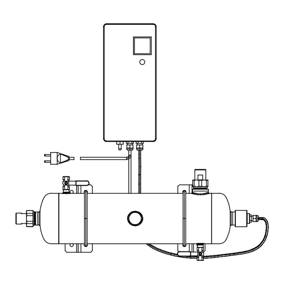
- Page 18 GENO-UV-60 I – 200 I Lamp cable Earth cable Mains cable Fig. D-1: Dimensional drawing of GENO-UV 60 I with optional wall bracket Lamp cable Earth cable Mains cable Fig. D-2: Dimensional drawing of GENO-UV 120 I (and 200 I) with optional floor rack Note: For the installation of devices with optional accessories (refer to chapter C-5.2), also observe the operation manuals...
- Page 19 Installation GENO-UV-60 I – 200 I 1.1 Sanitary installation Certain binding rules must always be observed when installing GENO-IV disinfection devices. Additional recommendations are given in order to facilitate working with the device. The installation information described here is also illustrated in Fig.
- Page 20 Installation GENO-UV-60 I – 200 I 2 Preliminary work 1. Unpack all components. 2. Check for completeness and undamaged condition. 3. Set up the device at the intended site. Note: The safest and easiest way to mount the device is to use the bracket for wall mounting available as an accessory or the floor rack (refer to chapter C-5.2).
- Page 21 Installation GENO-UV-60 I – 200 I Inlet shut-off valve (provided by others on site) Optional safety device (solenoid valve) Drinking water filter or backwash filter (accessories) Outlet shut-off valve (provided by others on site) Outlet flushing connection Inlet flushing connection Flow direction Solenoid valve ¼"...
- Page 22 (max. 230 VAC, 500 mA or max. 60 VDC, 500 mA). Electronic ballast Std.-Zähler Hour meter PE NC PE NO Fig. D-3: Terminal connection plan GENO-UV 60 I – 200 I Note: Control with on/off switch, operating LED and operating hour meter. Order no. 074 523 954-inter Author: mal-mrie G:\BA-523954-INTER_094-D.DOCX...
- Page 23 Start-up GENO-UV-60 I – 200 I E Start-up Table of contents 1 How to mount the protective quartz pipe ..... 1.1 GENO-UV 60 – 200 I ..........2 How to mount the UV lamp .......... 2.1 GENO-UV 60 – 200 I ..........The work described in this chapter can or rather should only be performed by Grünbeck’s technical service/authorised service or specially trained staff.
- Page 24 Start-up GENO-UV-60 I – 200 I 1.1 GENO-UV 60 I – 200 I 1. Unscrew the screw-in piece with spacer (pos. 7) from the brass screw connection (pos. 4) and loosen the cable screw connection of the screw-in piece. 2. Unscrew the screw connection (pos. 4) and remove the stainless steel binding ring (pos.
- Page 25 Operation Control unit GENO- UV I F Operation (control unit GENO-UV I) Table of contents 1 Operating panel ............1.1 Start / standard operation ........1.2 Stop ..............1 Operating panel Mains switch: to switch the system on/off Signal lamp: is illuminated during operation Operating hour meter: indicates total operating hours Fig.
- Page 26 Operation Control unit GENO-UV I 1.2 Stop The UV disinfection system is switched of via the mains switch (pos. 1) and the signal lamp (pos. 2) goes out. Note: The UV disinfection system should not be switched off without a reason as each switching process reduces the service life of the UV-lamp.
- Page 27 Troubleshooting GENO-UV-60 I – 200 I G Troubleshooting (GENO-UV systems I) Table of contents 1 General information ............. 2 Check UV lamp ............3 Mechanical destruction of lamp ........4 Mechanical destruction of lamp and protective quartz pipe ..........5 Binding and disposal of free mercury residue ..... 1 General information Even carefully designed and manufactured technical systems that are properly operated, may experience malfunctions.
- Page 28 Troubleshooting GENO-UV-60 I – 200 I 1. Switch off mains switch. 2. Unscrew screw-in piece (pos. 7) and pull out the UV lamp (no. 6) approx. 50 mm. 3. After a waiting period of 60 sec, switch on mains switch. 4.
- Page 29 Troubleshooting GENO-UV-60 I – 200 I 4 Mechanical destruction of lamp and protective quartz pipe In case of a mechanical destruction of the lamp and the lamp cladding pipe at the same time, the UV system must be dis- connected from the network and dismounted. The fragments of the cladding pipe and the lamp have to be removed through the mounting orifice of the quartz pipe.
- Page 30 Troubleshooting GENO-UV-60 I – 200 I Order no. 014 523 957-inter Edited by: mal-mrie G:\BA-523957-INTER_014_G.DOCX...
- Page 31 Maintenance and care GENO-UV-60 I – 200 I H Maintenance and care (GENO UV-I devices) Content 1 Basic information ............2 Service and maintenance ..........2.1 Service ..............2.2 Maintenance ............2.3 Overview of service work ........2.4 Overview of maintenance work ......2.5 Flushing the device ..........
- Page 32 Maintenance and care GENO-UV-60 I – 200 I 2 Service and maintenance Note: Make sure that each service and all maintenance work is recorded in the operation log. 2.1 Service The devices have to be serviced every 6 months. During service, if there is a safety device (solenoid valve) it will be checked for function, and the device will be checked for leakage and contam- ination.
- Page 33 Maintenance and care GENO-UV-60 I – 200 I 2.5 Flushing the device Flushing the UV device serves to remove deposits that have settled in the device during operation. These deposits are, for example, iron, manganese, copper, lime scale, etc. A flushing kit and a flushing agent (refer to chapter C-5) are required for flush- ing.
- Page 34 Maintenance and care GENO-UV-60 I – 200 I Order no. 044 523 958-inter Author: mal-mrie G:\BA-523958-INTER_044-H.DOCX...
- Page 35 Operation log Customer Name: ..............Address: ............................................... 60 I Disinfection device GENO-UV 120 I (Please check appropriate box) 200 I Serial number............Year of construction: ..........Installed by ............. Installed on ............Connection data: Drain connection DIN-1988 (Please check appropriate box) Floor drain available Line before disinfection...
- Page 37 Operation log GENO-UV disinfection devices Maintenance work on the UV disinfection system GENO-UV Checklist Please enter measured values. Confirm checks with Yes/No or OK or enter repair work performed. Maintenance performed (date) Operating hours [h] Safety device checked System checked for tightness UV lamp changed UV lamp plug checked Quartz glass seal checked...
- Page 38 Operation log GENO-UV disinfection devices Maintenance work on the UV disinfection system GENO-UV Checklist Please enter measured values. Confirm checks with Yes/No or OK or enter repair work performed. Maintenance performed (date) Operating hours [h] Safety device checked System checked for tightness UV lamp changed UV lamp plug checked Quartz glass seal checked...
- Page 39 Operation log GENO-UV disinfection devices Maintenance work on the UV disinfection system GENO-UV Checklist Please enter measured values. Confirm checks with Yes/No or OK or enter repair work performed. Maintenance performed (date) Operating hours [h] Safety device checked System checked for tightness UV lamp changed UV lamp plug checked Quartz glass seal checked...
- Page 40 Operation log GENO-UV disinfection devices Maintenance work on the UV disinfection system GENO-UV Checklist Please enter measured values. Confirm checks with Yes/No or OK or enter repair work performed. Maintenance performed (date) Operating hours [h] Safety device checked System checked for tightness UV lamp changed UV lamp plug checked Quartz glass seal checked...
Need help?
Do you have a question about the GENO-UV 60 I and is the answer not in the manual?
Questions and answers