Table of Contents
Advertisement
Quick Links
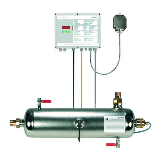
Disinfection systems GENO-UV 60 S
Edition May 2019
Order no. 264 523 940-inter
According to the list given in §11 of the German Drinking Wa-
ter Ordinance, GENO-UV disinfection systems intended for the
application in drinking water must be operated according to
DVGW worksheet W 294-1. This is only possible with systems
tested and certified according to worksheet W 294-2
The UV disinfection systems type GENO-UV 60 S, 120 S and
200 S described in this operation manual comply with this re-
quirement.
Operation Manual
120 S
200 S
Advertisement
Chapters
Table of Contents

Related Manuals for Grunbeck GENO-UV 60 S


Summary of Contents for Grunbeck GENO-UV 60 S
- Page 1 DVGW worksheet W 294-1. This is only possible with systems tested and certified according to worksheet W 294-2 The UV disinfection systems type GENO-UV 60 S, 120 S and 200 S described in this operation manual comply with this re- quirement.
- Page 3 Content Content This operation manual consists of several parts as shown in the table below. Please refer to the cover sheets of the individual parts for detailed information on their contents General..............Basic information ............. Product description ..........Installation ............... Start-up..............
- Page 4 89420 Hoechstaedt/Germany Responsible for documentation: Markus Pöpperl System designation: Disinfection system System type: GENO-UV 60 S; GENO-UV 120 S; GENO-UV 200 S Serial number: Refer to type designation plate Applicable guidelines: Low voltage (2014/35/EU) EMC (2014/30/EU) Applied harmonised standards, in...
- Page 5 General A General Table of contents 1 | Preface ..............2 | How to use this operation manual ......3 | General safety information ........3.1 Symbols and notes ..........3.2 Operating personnel ..........3.3 Designated application ........3.4 Protection from water damage ......3.5 Indication of specific dangers ......
- Page 6 General 2 | How to use this operation manual This operation manual is intended for the operators of our sys- tems. It is divided into several chapters (a letter is assigned to each of them) which are listed in the “Table of contents” on page 1 in alphabetical order.
- Page 7 General 3.2 Operating personnel Only persons who have read and understood this operation manual are permitted to work with the system. The safety guide- lines are to be strictly adhered to. 3.3 Designated The system may only be used for the purpose outlined in the application product description (chapter C).
- Page 8 General 4 | Shipping and storage Attention! The system may be damaged by frost or high tem- peratures. In order to avoid damage of this kind: Protect from frost during transportation and storage! Do not in- stall or store system next to objects which radiate a lot of heat. The system may only be transported and stored in its original packing.
- Page 9 Basic information GENO-UV disinfection B Basic information (GENO-disinfection systems) Contents 1 Laws, regulations, standards ........2 Disinfecting effect of UV light ........3 Room irradiation ............1 Laws, regulations, standards In the interest of good health, rules cannot be ignored when it comes to the processing of drinking water.
- Page 10 Basic information GENO-UV disinfection 2 Disinfecting effect of UV light UV light (ultraviolet light) is light of wave lengths between 100 and 380 nm which are imperceptible (invisible) to the naked eye. For the UV disinfection, the wave length of 254 nm is of major importance.
- Page 11 Basic information GENO-UV disinfection 3 Room irradiation The extent of the irradiation in the room depends on the intensity and the duration of the irradiation. The irradiation intensity on the other hand depends on the spectral absorption coefficient of the water at 254 nm (SAC ).
- Page 12 Basic information GENO-UV disinfection Order no. 084 523 942-inter Edited by: mal-mrie G:\BA-523942-INTER_084_B.DOCX...
-
Page 13: Table Of Contents
Product description GENO-UV 60 S – 200 S C Product description (GENO-UV 60 S – UV 200 S) Content 1 Type designation plate ..........2 Technical specifications ..........3 Designated application ..........4 Application restrictions..........4.1 Application in drinking water ....... -
Page 14: Technical Specifications
Product description GENO-UV 60 S – 200 S Table C-1: Technical specifications Disinfection devices GENO-UV 60 S 120 S 200 S Connection data Nominal connection diameter DN 25/R 1“ DN 40/R 1 ½“ DN 50/R 2“ Drain connection, min. DN 50... -
Page 15: Designated Application
Product description GENO-UV 60 S – 200 S 3 Designated application The GENO-UV disinfection systems are designed for the disin- fection of drinking water. They are to be installed downstream of water treatment systems. The room irradiation required to kill bacteria and viruses is min. -
Page 16: Application Restrictions
Product description GENO-UV 60 S – 200 S 4 Applications restrictions The SAK value (specific absorption coefficient at a wave length of the light of 254 nm) indicates how much light is lost in the water. As in a lot of water analyses the water transmission is also given, this value is included in the tables below as well. - Page 17 Index for operation GENO-UV 60 S DVGW-tested index point DVGW-tested index point Flow [m³/h] Fig. C-1 Index for suitability and index for operation GENO-UV 60 S Index for suitability GENO-UV 120 S Index for operation GENO-UV 120 S DVGW-tested index point DVGW-tested index point Flow [m³/h]...
-
Page 18: Scope Of Delivery
Product description GENO-UV 60 S – 200 S 5 Scope of delivery 5.1 Basic equipment • 1 Stainless steel pressure vessel • 1 Protective quartz pipe • 1 Moulded seal for protective quartz pipe • 1 UV lamp Note: For the UV lamps, a special warranty of max. 4000 operat- ... -
Page 19: Consumables
Product description GENO-UV 60 S – 200 S Note: Existing systems may be equipped with optional compo- nents. Our field service staff in your area as well as the Grünbeck headquarters will be pleased to submit further information. 5.3 Consumables In order to ensure the reliable operation of the system, only gen- uine consumables should be used. -
Page 20: Spare Parts
GENO-UV 60 S GENO-UV 120 S 523 121e GENO-UV 200 S 523 131e 523 620 • Spare protective quartz pipe GENO-UV 60 S GENO-UV 120 S 522 627 GENO-UV 200 S 522 628 523 615 • Control unit GENO-Multi BS Warning: To ensure the proper and safe operation of your UV system, only and exclusively use Grünbeck’s genuine spare... - Page 21 Installation GENO-UV 60 S – UV 200 S D Installation Contents 1 General installation information ........1.1 Water installation ........... 1.2 Electrical installation ..........2 Preliminary work ............3 How to connect the system ......... 3.1 Water connection ..........3.2 Electrical connection ..........
-
Page 22: General Installation Information
Installation GENO-UV 60 S – UV 200 S 1 General installation information The installation site must offer adequate space. The required connections must be provided prior to the installation. For di- mensions and connection data, please refer to table D-1. -
Page 23: Water Installation
Installation GENO-UV 60 S – UV 200 S 1.1 Water installation While installing the GENO-UV disinfection systems, certain rules must be strictly observed. Additional recommendations are given in order to facilitate the handling of the systems. The installation information described below is also illustrated in fig. D-2. -
Page 24: Electrical Installation
Installation GENO-UV 60 S – UV 200 S Attention! Without the safety device, the UV disinfection system cannot be operated according to the German Drinking Water Or- dinance. There is a risk that water which is not or insufficiently disinfected might enter the installation downstream of the system and contaminate the piping. - Page 25 Installation GENO-UV 60 S – UV 200 S Fig. D-2 Installation drawing Inlet shut-off valve Outlet shut-of valve Flushing connection inlet (by others on site) (by others on site) Drinking water filter or backwash fil- Flow direction Solenoid valve for temperature-...
-
Page 26: Electrical Connection
Installation GENO-UV 60 S – UV 200 S 3.2 Electrical connection The required electrical connections must be implemented ac- cording to terminal plan D-3, D-4. The work specified in this chapter may only be performed by trained and authorised electricians or electronics experts. - Page 27 Installation GENO-UV 60 S – UV 200 S Bestrahlungsstärke Voralarm N.C. max. 24 V~ / max. 1 A Irradiation pre-alarm active, max. 24 V~ / max. 1 A Pré-alarme intensité de rayonnement N.C. Wartungsmeldung aktiv max. 24 V~ / max. 1 A Maintenance signal active, max.
- Page 28 Installation GENO-UV 60 S – UV 200 S Pos. Component Terminal Signal Colour of litz wire Feeder XP1 L 230 V / 50 Hz Phase brown resp. Fuses F1 and F2 black (2 A T each) internal fuse protec- XP1 N...
- Page 29 Start-up GENO-UV 60 S – UV 200 S E Start-up Contents How to mount the protective quartz pipe ..... How to mount the UV lamp ........How to set the control unit ........How to start up the system ........
- Page 30 Start-up GENO-UV 60 S – UV 200 S Fig. E-1 Installation drawing for type 60 – 200 AS 1. Unscrew the screw-in piece with spacer (pos. 7) from the brass screw connection (pos. 4) and loosen the cable screw connection of the screw-in piece.
- Page 31 Start-up GENO-UV 60 S – UV 200 S 1. Insert the UV lamp (pos. 6) into the protective quartz pipe (pos. 2) up to approx. 60 mm. 2. Connect the UV lamp (pos. 6) to the plug in the stainless steel cap (pos.
- Page 32 Start-up GENO-UV 60 S – UV 200 S 4 How to start up the system Warning! There is a possibility that the drinking water is insuffi- ciently disinfected. According to the DVGW worksheet W 291 (technical regulations for the disinfection of water supply sys- tems) the piping downstream of the UV system must be disin- fected prior to start-up.
- Page 33 Operation GENO-Multi BS F Operation (GENO-UV Multi BS) Contents 1 Preface ..............2 How to operate the control unit ........ 2.1 Operating panels and display ......2.2 System start ............2.3 Switching off the system ........2.4 Pre-warning and maintenance display ....2.5 Error display ............
-
Page 34: How To Operate The Control Unit
Operation GENO-Multi BS 2 How to operate the control unit 2.1 Operating panels and display Fig. F-2: Operating panels and display 2.1.1 Display of Info level Display Unit Basic display of irradiation intensity XX.XX W/m² Operating duration XXXX Days Switch on processes XXXX Days until service is due XXXd Days Return to basic display of irradiation intensity... -
Page 35: System Start
Operation GENO-Multi BS 2.1.2 Parameter programming Key functions with parameter programming – requirement: basic display of irradiation intensity [W/m²]. Display • Press and hold key > 1 sec.: access to operator programming level (optional: temperature rinsing system). • Open the parameter for reprogramming – value begins to flash. •... -
Page 36: Switching Off The System
Operation GENO-Multi BS 2.3 Switching off the sys- • The current-free, closed solenoid valves (optional safety and rinsing solenoid valve) close (flow is interrupted). • The ALARM, pre-warning and service voltage-free contacts open. Note: The UV system should not be switched off without a rea- ... - Page 37 Troubleshooting GENO-UV systems with GENO-Multi BS G Troubles hooting (GENO UV s ys tems with GENO-UV-Multi BS) Contents 1 Basic information ............2 Check UV lamp ............3 Mechanical destruction of the lamp ......4 Mechanical destruction of the lamp and the protec- tive quartz pipe ............
- Page 38 Troubleshooting GENO-UV systems with GENO-Multi BS Table G-1: Troubleshooting This is what you observe This is the cause This is what to do Er 1 and UV lamp light up. Irradiation intensity < limit value. Clean the system (rinse). • System is soiled inside.
-
Page 39: Check Uv Lamp
Troubleshooting GENO-UV systems with GENO-Multi BS 2 Check UV lamp Please observe the instructions given below when checking the UV lamp. The work processes specified are shown in Fig. E-1. Danger! Danger due to electric energy! Do not touch or replace the UV lamps unless the mains switch has been switched off. -
Page 40: Mechanical Destruction Of The Lamp And The Protective Quartz Pipe
Troubleshooting GENO-UV systems with GENO-Multi BS Warning! As, due to the destruction of the lamp, mercury will escape, the lamp fragments must be stored in an air-tight con- tainer until they can be disposed of. The same applies for a re- placed protective quartz pipe and for the detergent used for cleaning purposes. -
Page 41: Basic Information
Maintenance and care GENO-UV systems with GENO-Multi BS H Maintenance and care (GENO UV s ys tems with GENO-Multi BS) Contents 1 Basic information ............2 Inspection ..............3 Service and maintenance .......... 3.1 Overview of service work ........3.2 Overview of maintenance work (375 days of operation). - Page 42 Maintenance and care GENO-UV systems with GENO-Multi BS 2 Inspection You can carry out regular inspection yourself - this is mandatory at least every two months. Check for tightness of all system components. Check the control unit for errors (see chapter G, malfunctions). 3 Service and maintenance 3.1 Overview of service work (every 183 days of operation) •...
- Page 43 Maintenance and care GENO-UV systems with GENO-Multi BS 3.4 System rinsing By rinsing the UV system, deposits which have settled on the system during operation are removed. These deposits are for example iron, manganese, copper, scale etc. For rinsing, a rins- ing set and rinsing agent are required (see chapter C-5).
- Page 44 Maintenance and care GENO-UV systems with GENO-Multi BS 4 Information regarding operation log The operation log is located in the insert at the back of this folder. When starting up the system, make sure to record all data on the cover sheet of the operation log and fill in the first column of the checklist.
- Page 45 Operation log GENO-UV disinfection systems Test certificate and DVGW certificate according to DVGW work sheet W 294 Order no. 144 523 951-inter Edited by: mal-mrie G:\BA-523951-INTER_144_BHB.DOCX...
- Page 46 Operation log GENO-UV disinfection systems Order no. 144 523 951-inter Edited by: mal-mrie G:\BA-523951-INTER_144_BHB.DOCX...
- Page 47 Operation log GENO-UV disinfection systems Order no. 144 523 951-inter Edited by: mal-mrie G:\BA-523951-INTER_144_BHB.DOCX...
- Page 48 Operation log GENO-UV disinfection systems Order no. 144 523 951-inter Edited by: mal-mrie G:\BA-523951-INTER_144_BHB.DOCX...
- Page 49 Operation log GENO-UV disinfection systems Order no. 144 523 951-inter Edited by: mal-mrie G:\BA-523951-INTER_144_BHB.DOCX...
- Page 50 Operation log GENO-UV disinfection systems Order no. 144 523 951-inter Edited by: mal-mrie G:\BA-523951-INTER_144_BHB.DOCX...
- Page 51 Operation log GENO-UV disinfection systems System designation GENO-UV 60 S 120 S 200 S General manufacturer/distributor Grünbeck Wasseraufbereitung GmbH Pressure stage PN 10 Temperature range 5 – 30 °C 30-70°C Installation position/flow direction horizontal / centric inlet (on left), radial outlet (upper right) Nominal connection diameter 1“...
- Page 52 Operation log GENO-UV disinfection systems Type designation plate GENO-UV 60 S Type designation plate GENO-UV 120 S Type designation plate GENO-UV 200 S Order no. 144 523 951-inter Edited by: mal-mrie G:\BA-523951-INTER_144_BHB.DOCX...
- Page 53 Operation log GENO-UV disinfection systems Operation log Customer Name: ..............Address: ............................................60 S GENO -UV disinfection system 120 S (please check appropriate box) 200 S Serial number ............Year of construction: ..........Installed by ............Installed on ............Connection data: Drain connection DIN 1988 Floor drain available...
- Page 54 Operation log GENO-UV disinfection systems Maintenance work on UV disinfection systems GENO-UV Checklist Please enter measured values. Confirm checks with YES/NO or OK or record repair work performed. Maintenance performed (date) Start-up Max. flow rate (also indicate colour of flow stabiliser) [m³/h] Flow stabiliser replaced Irradiation intensity pre-warning [W/m²] (control on electronics)
- Page 55 Operation log GENO-UV disinfection systems Maintenance work on GENO-UV disinfection systems Checklist Please enter measured values. Confirm checks with YES/NO or OK or record repair work performed. Maintenance performed (date) Max. flow rate (also indicate colour of flow stabiliser) [m³/h] Flow stabiliser replaced Irradiation intensity pre-warning [W/m²] (control on electronics)
- Page 56 Operation log GENO-UV disinfection systems Maintenance work on GENO-UV disinfection systems Checklist Please enter measured values. Confirm checks with YES/NO or OK or record repair work performed. Maintenance performed (date) Start-up Max. flow rate (also indicate colour of flow stabiliser) [m³/h] Flow stabiliser replaced Irradiation intensity pre-warning [W/m²] (control on electronics)
- Page 57 Operation log GENO-UV disinfection systems Maintenance work on GENO-UV disinfection systems Checklist Please enter measured values. Confirm checks with YES/NO or OK or record repair work performed. Maintenance performed (date) Max. flow rate (also indicate colour of flow stabiliser) [m³/h] Flow stabiliser replaced Irradiation intensity pre-warning [W/m²] (control on electronics)
Need help?
Do you have a question about the GENO-UV 60 S and is the answer not in the manual?
Questions and answers