Advertisement
Quick Links
C u s t o m e r S e r v i c e S e c t i o n
Edition February 2012
Order no. 054 523 950 – inter
-CONFIDENTIAL-
of the operation manual for
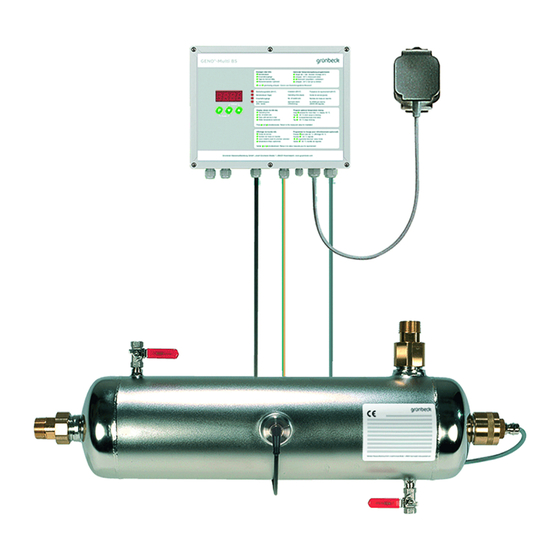
disinfection systems GENO
This special customer service section contains information that
is essential for the start-up, maintenance resp. repair of the
systems and therefore has to be carried along at all times.
However, this additional information may only be used in
combination with the standard operation manual. Furthermo-
re, it is only designated for the technical customer service.
The customer service section consists of a lose collection of
sheets that should – according to the respective chapter and
page number (refer to header and footer) – be attached to the
corresponding chapters of the standard operation manual.
In order to always be well informed, it is important to keep
the complete customer service section of the operation manual
up to date at all times.
Grünbeck Wasseraufbereitung GmbH
Josef-Grünbeck-Strasse 1
89420 Hoechstaedt/Danube · GERMANY
Phone +49 9074 41-0 · Fax +49 9074 41-100
www.gruenbeck.com · info@gruenbeck.com
®
-UV 60 S
A company certified by TÜV SÜD
in accordance with DIN EN ISO 9001, DIN
EN ISO 14001, DIN EN ISO 13485 and SCC
120 S
200 S
Advertisement

Subscribe to Our Youtube Channel
Related Manuals for Grunbeck GENO-UV 60 S


Summary of Contents for Grunbeck GENO-UV 60 S
- Page 1 C u s t o m e r S e r v i c e S e c t i o n of the operation manual for ® disinfection systems GENO -UV 60 S 120 S 200 S This special customer service section contains information that is essential for the start-up, maintenance resp.
- Page 3 SAK of 2.7 m . This means that the UV systems GENO-UV 60 S, 120 S and 200 S are suita- ble for water with a SAK of up to 2.7 m . Water that has a...
- Page 4 System flow irradiance m³/h W/m² GENO-UV 60 S 11.5 GENO-UV 120 S 94.0 74.1 55.0 14.0 GENO-UV 200 S 12.0 16.0 1.2 How to set the minimum At installation sites at which the system is to be operated without...
- Page 5 Operation GENO -Multi BS ® F Operation (GENO -Multi BS) Contents 1 Preface................. 2 How to operate the control unit ........2.1 Operating panels and display ........ 2.2 Operation programming level ....... 2.3 Installer level code 290 ......... 2.4 Error memory code 245 ........2.5 Displaying the software version code 999 .....
-
Page 6: Operation
Operation GENO -Multi BS 2 | Operating the control unit 2.1 Operating panels and display Fig. F-2: Operating panels and display 2.1.1 Displaying the Info level Display Unit W/m² Basic display of irradiance XX.XX Operating duration XXXX Days Switch on processes XXXX Time until service is due XXXd Days Back to basic display of irradiance... - Page 7 Operation GENO -Multi BS 2.1.2 Programming parameters Key functions with parameter programming – requirement: Basic display of irradiance [W/m²]. Display Press the key > 1 sec.: Access to parameter programming (opt. temperature flushing system). Open the parameter for reprogramming – the value begins to flash. ...
- Page 8 Operation GENO -Multi BS 2.3 Installer level Code 290 Note: The parameters specified below should only be modified by trained experts as incorrect values may lead to malfunctions or insufficient disinfected drinking water. Requirement: The control unit shows the basic display of irradi- ance.
- Page 9 Operation GENO -Multi BS The FIFO error memory covers the last 20 malfunctions including 2.4 Error memory the time stamp of how many operating hours ago the malfunction Code 245 occurred. The malfunction no. 20 lying furthest back is deleted from the memory in each case when a new malfunction occurs.
- Page 10 Operation GENO -Multi BS 2.6 Customer service level code 302 Index Parameter, Unit Factory Setting Note setting range Calibration of UV sensor Current 0 … 45.0 see chapter H, 2.1 [W/m²] irradiance Irradiance limit value According 0 … 45.0 see chapter E, 1.2 [W/m²] to currently...
- Page 11 Troubleshooting - Customer Service Section GENO ® UV systems with GENO ® -Multi BS G Troubleshooting - Customer Service Section ® ® (GENO UV systems with GENO Multi BS control unit) The causes of errors are tabulated in the order of their probable frequency.
- Page 12 Maintenance and Care - Customer Service Section GENO ® UV systems with GENO ® -Multi BS Continuation Table 1: This is what you observe This is the cause This is what to do Set rinsing temperature lower. Er 4 Excess temperature (only when the optional temperature flushing sys- ...
- Page 13 Maintenance - Customer Service Section GENO ® UV systems with GENO ® -Multi BS H Maintenance - Customer Service Section ® ® (GENO UV systems with GENO -Multi BS) Contents 1 Overview of service and maintenance work ....2 Calibration of the system sensor ........3 Resetting ..............
- Page 14 Maintenance - Customer Service Section GENO ® UV systems with GENO ® -Multi BS 1.3 Overview of maintenance work (every 730 days of operating duration or every 18,000 operating hours) All service work and in addition: Replace UV lamp with GENO ®...
- Page 15 Maintenance - Customer Service Section GENO ® UV systems with GENO ® -Multi BS 2 | Calibration of the UV system sensor If the deviation between the UV system sensor and the reference measuring device is in a range of ± 5 – 10 %, the system sensor may be recalibrated.
- Page 16 Maintenance - Customer Service Section GENO ® UV systems with GENO ® -Multi BS 3 | Resetting the operating hours and the switch-on counter After replacing the lamp, the operating duration and switch-on counter should be reset: Reprogramme the code level 189, par. 0…0 to 0…1 operating duration, switch-on counter and error memory are deleted.
Need help?
Do you have a question about the GENO-UV 60 S and is the answer not in the manual?
Questions and answers