
Subscribe to Our Youtube Channel
Related Manuals for Grunbeck GENO-OSMO-X 180


Summary of Contents for Grunbeck GENO-OSMO-X 180
- Page 1 We understand water. Reverse osmosis system | GENO-OSMO-X permeate stage Operation manual...
- Page 2 General Contact Germany International Sales Phone +49 9074 41-145 Technical Service Phone +49 9074 41-333 Fax +49 9074 41-120 Availability Monday to Thursday 7:00 am - 6:00 pm Friday 7:00 am - 4:00 pm Original operation manual Edition: November 2022 Order no.: 100115500000_en_074...
-
Page 3: Table Of Contents
Table of contents Table of contents Checking the 2-stage system ........44 Table of contents .............. 3 Setting the control unit ..........45 Handing over the product to the owner/operating Introduction ............. 4 company ..............45 Validity of the manual ..........4 Other applicable documents ........5 Operation/handling ..........46 Product identification .......... -
Page 4: Introduction
Introduction Introduction This manual is intended for owners/operating companies, operators/users as well as qualified specialists and ensures the safe and efficient handling of the product. The manual is an integral part of the product. ► Carefully read this manual and the included manuals on the components before you operate your system. -
Page 5: Other Applicable Documents
Introduction Other applicable documents ● Operation manual Reverse osmosis system GENO-OSMO-X (order no.: 750 927 ● Manuals of all accessories used ● Manuals of components from other manufacturers ● Safety data sheets for chemicals ● Electric circuit diagram, order no.: 750 292 and 751 292 Product identification You can identify your product based on the product designation and the order number shown on the type plate. -
Page 6: Symbols Used
Introduction Symbols used Symbol Meaning Danger and risk Important information or requirement Useful information or tip Written documentation required Reference to further documents Work that must be carried out by qualified specialists only Work that must be carried out by qualified electricians only Work that must be carried out by technical service personnel only Depiction of warnings This manual contains information and instructions that you must obey for your personal... -
Page 7: Demands On Personnel
Introduction Demands on personnel During the individual phases in the service life of the system, different persons carry out work on the systems. The respective tasks require different skills. 1.6.1 Qualification of personnel Personnel Requirements • No special expertise required Operator/user •... - Page 8 Introduction 1.6.3 Personal protective equipment ► As an owner/operating company, make sure that the required personal protective equipment is available. The components below fall under the heading of personal protective equipment (PPE): Protective gloves Protective footwear Protective overall Protective goggles Hard hat Mask Face shield...
-
Page 9: Safety
Safety Safety Safety measures ● Only operate the system if all components are installed properly. ● Obey the local regulations on drinking water protection, accident prevention and occupational safety. ● Do not make any changes, alterations, extensions or program changes on your product. - Page 10 Safety ● Never bridge electrical fuses. Do not disable fuses. Use the correct current ratings when replacing fuses. ● Keep moisture away from live parts. Moisture can cause short-circuits. 2.1.4 Danger due to chemicals ● Chemicals can be harmful to the environment and/or to health. They can cause skin and eye burns as well as irritation of the respiratory tract or allergic reactions.
-
Page 11: Product-Specific Safety Instructions
Safety 2.1.5 Groups of persons requiring protection ● This product can be used by persons with limited abilities or lack of experience if they are supervised or instructed in the safe use of the system and understand the resulting hazards. ●... - Page 12 Safety 2.2.1 Signals and warning signs Warnings/pictograms Risk of electric shock (attached to the distributor cover and in the power distribution/electrical switch cabinet) ► Disconnect the system from the power supply before working on electrical system parts Risk of electric shock due to residual voltage High voltage can be present even if the LED warning indicator is not illuminated.
-
Page 13: Product Description
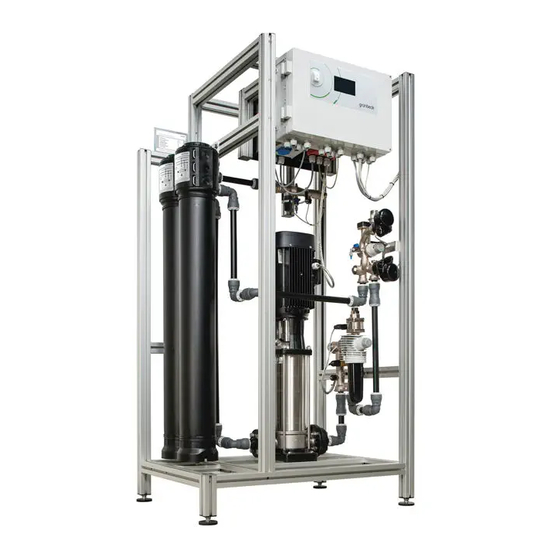
Product description Product description The reverse osmosis system GENO-OSMO-X permeate stage (2nd stage) is mounted on an aluminium system rack and ready for connection. The reverse osmosis system GENO-OSMO-X permeate stage (2nd stage) features connecting pipes to the 1st stage. A transfer unit with transfer station for feed water, concentrate and permeate is installed in the 1st stage. -
Page 14: Product Components
Product description Product components 3.3.1 GENO-OSMO-X permeate stage Designation Function Coding Piping with connections: Feed water inlet, concentrate-to- Transfer unit drain and permeate outlet are installed on the system rack Installed in the hydro block Permeate of the 1st stage. For Pressure transducer RO1CP2 constant pressure control of the 1st stage... -
Page 15: System Connections
Product description 3.3.2 GENO-OSMO-X with GENO-OSMO-X permeate stage Designation Designation GENO-OSMO-X (1st stage) GENO-OSMO-X permeate stage (2nd stage) System connections Designation Designation GENO-OSMO-X (1st stage) Feed water inlet BL1 (1" m. thr. or 1¼" m. thr.) GENO-OSMO-X permeate stage (2nd stage) Concentrate outlet to drain BL2 (1"... -
Page 16: Functional Description
Product description Functional description The reverse osmosis system consists of the functional units below: Feed water Concentrate-to-drain Permeate Designation Designation Pressure pipe with membrane module Hydro block Concentrate-to-drain (1st stage) (2nd stage) (number subject to system size) Hydro block Concentrate-to-drain (1st stage) Hydro block Permeate (1st stage) Hydro block Feed water (1st stage) Hydro block Permeate (2nd stage) - Page 17 Product description Hydro block Feed water 1st stage Designation Function Coding Connection Water meter screw connection 1" or 1¼" (male thread) with flat sealing Feed water inlet Prefiltration of the feed water incl. pressure reducer (preset) 4.0 bar and integrated pressure gauge. Fine filter RO1F1 Osmosis version with black filter cylinder and filter element.
- Page 18 Product description Hydro block Concentrate 1st stage Designation Function Coding Connection Water meter screw connection 1" (male thread) with flat sealing Concentrate-to-drain To automatically adjust the volume flow Concentrate-to-drain Adjusting valve (recovery). During the production of permeate, this portion of the RO1V3 water permanently flows to the drain.
- Page 19 Product description Designation Function Coding Sampling valve Concentrate of permeate Allows for manual quality determination via the sampling valve RO1H11 stage Adjusting valve For automatic adjustment of the volume flow Concentrate Concentrate recirculation RO1V9 recirculation. The volume flow depends on the system size with drive Hydro block Permeate 1st stage Designation...
-
Page 20: Accessories
Product description Accessories Your product can be retrofitted with accessories. Please contact your local Grünbeck representative or Grünbeck’s headquarters in Hoechstaedt/Germany for details. Illustration Product Order no. Drinking water filter BOXER KX 1" 101 835 80 µm filter element for prefiltration Drinking water filter BOXER KDX 1"... - Page 21 Product description Illustration Product Order no. GENO-membrane degassing system MEC 500-1 770 200 For a permeate capacity < 500 l/h, chemical-free removal of CO disturbing the process using a porous membrane. On-site stripping gas supply as oil-free and aerosol-free compressed air 3 - 10 bar required. Optional: Integrated in the rack-mounted modular system of the GENO-OSMO- X permeate stage.
- Page 22 Product description Illustration Product Order no. Combined unit 712 820 trap SL3K with sterile air filter (optional) For sterile aeration and ventilation (ventilation line up to 5.0 m³/h) of permeate tanks to retain germs and particles and to remove CO from the ambient air.
-
Page 23: Transport, Placing And Storage
Transport, placing and storage Transport, placing and storage Shipping/Delivery/Packaging The system is fixed on a pallet at the factory and secured against tipping. ► Load and unload the system with a forklift/lift truck with suitable pallet forks. Take note of the system’s top-heavy centre of gravity. NOTE Risk of damage when lifting the system with a crane and lifting strap. -
Page 24: Installation
Installation Installation The installation of the system represents a major intervention into the drinking water system and must be carried out by a qualified specialist only. Installation example GENO-OSMO-X permeate stage Designation Designation Drinking water filter (e.g. BOXER KDX) Reverse osmosis system GENO-OSMO-X Pure water tank GT-X with level probe System separator GENO-DK 2 Accessories: CO... -
Page 25: Requirements For The Installation Site
Installation Installation example GENO-OSMO-X permeate stage „Membrane degassing and UV system” Designation Designation GENO-membrane degassing system Drinking water filter (e.g. BOXER KDX) MEC 500-1, integrated in system rack of System separator GENO-DK 2 the 2nd stage Pure water tank RT-X with level probe Water softener Delta-p-I Accessories: CO trap with sterile air filter... - Page 26 Installation 5.2.1 Placing of the system/Required space ● The sufficiently dimensioned installation surface of the system (foundation) must be level and have sufficient strength and load-bearing capacity to support the operating weight of the system. ● For installation and maintenance work, a sufficient distance of at least 500 mm must be maintained in front/behind and to the right of the system.
-
Page 27: Checking The Scope Of Supply
Installation Checking the scope of supply The reverse osmosis systems GENO-OSMO-X (1st stage) and GENO-OSMO-X permeate stage (2nd stage) are each pre-assembled on an aluminium rack and ready for connection. Designation Designation Connection nozzle (to flush out the GENO-OSMO-X (1st stage) with transfer unit preserving agent) GENO-OSMO-X permeate stage (2nd sage), 4x spacer (1st stage to 2nd stage) - Page 28 Installation 5.4.1 Preliminary work High difference in temperature at the installation site during the installation NOTE of the system. ● Possible malfunction of the control unit during initial start-up/commissioning due to moisture condensation on electronic components inside the control unit. ►...
- Page 29 Installation Designation Designation Spacer Adjustable feet 9. Level out any uneven floors with the adjustable feed. 10. Position the spacers at the top and the bottom of the system racks. 11. Fix the system racks with the angles of the spacers. »...
- Page 30 Installation Designation Designation Shut-off valve (to be provided by client on site) Aeration/ventilation valve Flushing section (to be provided by client on Drain connection acc. to DIN EN 1717 site) 1. Install a flushing section each in the inlet pipe “feed water” and the outlet pipe “permeate”.
-
Page 31: Electrical Installation
Installation Electrical installation The electrical installation must be carried out by a qualified electrician only. DANGER Life-threatening voltage of 400 V ● Risk of severe burns, cardiovascular failure, fatal electric shock ► Check the system for proper condition before start-up/commissioning. ►... - Page 32 Installation 1. Remove the bag with the connection material from the power distribution box. 2. Connect the grounding point to the aluminium rack – use the connection material: hammer nut, hexagon head screw M8x25 and serrated washer. 3. Attach the “Grounding” label. 4.
- Page 33 Installation ► Close the power distribution. ► Fold up the control unit and secure it with the lock. ► Prior to starting up the system, make sure that the control unit/power distribution is closed – the main switch must be in the OFF position. 5.5.3 Line connections (control unit GENO-OSMO-X 2nd stage) WARNING...
- Page 34 Installation 5.5.3.1 Terminal strip of motherboard The line connections below are pre-installed in the system at the factory and must not be modified: Power supply of operating board Terminal from motherboard Function Terminal to operating board 24 VDC / 500 mA Ground RS-485 (III) serial interface Terminal from motherboard...
- Page 35 Installation Connections of the motherboard Term. Signal Colour Function Line Comment Mains switch on housing cover H05VV-F 5G1.5 mm² From mains switch To mains switch Protective conductor 230 V~ power supply H05VV-F 3G0.75 mm² Mains input from power distribution RO1E2 Protective conductor + 24 V= Frequency converter...
- Page 36 Installation 5.5.4 Line connections to other subsystems Obey the operation manuals of the subsystems. 5.5.4.1 Interface RS-485 Data line to interconnected subsystems Water softener and/or Pressure booster Connecting terminating resistors If more than two subsystems are interconnected or if the length of the line between the two is >...
-
Page 37: Start-Up/Commissioning
Start-up/Commissioning Start-up/Commissioning The initial start-up/commissioning of the product must be carried out by technical service personnel only. Climbing onto system components when operating components that are CAUTION located at high levels. ● Risk of falling when climbing onto system components ●... - Page 38 Start-up/Commissioning 6.1.1 Flushing the 1st stage ► Prepare the 1st stage as follows: Designation Designation Permeate pipe to 2nd stage Connection nozzle 1. Disconnect the connection of the permeate pipe to the 2nd stage from the hydro block Permeate 1st stage. 2.
- Page 39 Start-up/Commissioning ► Flush out the 1st stage as follows: Designation Designation Shut-off valve Feed water inlet Flushing line provided by the client on site Flushing section of permeate pipe 1. Remove the flushing section from the permeate pipe. 2. Route the flushing line provided by the client on site from the permeate outlet of the 1st stage to the drain.
- Page 40 Start-up/Commissioning 6. Tap on START. » The feed water solenoid valve, the concentrate-to-drain control valve and at times the control valve for concentrate recirculation are opened. » The system automatically stops flushing when three times the flushing volume has been flushed to the drain (duration subject to system size and programmed flushing volume).
- Page 41 Start-up/Commissioning 6.1.2 Flushing the 2nd stage ► Prepare the 2nd stage as follows: 1. Disconnect the connection of the concentrate pipe to the 2nd stage from the hydro block Concentrate (adjusting valve RO1V10). 2. Insert the connection nozzle for flushing out the preserving agent into the hydro block Concentrate.
- Page 42 Start-up/Commissioning 4. Open the shut-off valve of the “feed water” inlet. ► Flush out the 2nd stage as follows: 1. Tap on the system GENO-OSMO-X 1st stage in the display. 2. In the user programming level of the 1st stage, go to Jog mode (Code 653). When quitting the jog mode, all settings in this level are automatically reset.
- Page 43 Start-up/Commissioning 6. After 30 minutes of flushing, check the conductivity as follows: a Take samples at the sampling valves RO1H11 (2nd stage) and RO1H1 (1st stage). b Compare the conductivity. » The conductivity should be about the same. 7. Continue with the flushing process if the conductivity shows too great a difference. Compare the conductivity once again after approx.
-
Page 44: Checking The 2-Stage System
Start-up/Commissioning Checking the 2-stage system CAUTION Risk of slipping at the sampling points. ● You might slip/fall and injure yourself. ► Use personal protective equipment - wear sturdy shoes. ► Immediately mop up escaped liquid. 1. Let the 2-stage system run in for at least 20 minutes. 2. -
Page 45: Setting The Control Unit
Start-up/Commissioning Setting the control unit 1. Make the basic settings (refer to chapter 7.1.1). 2. Check the operating mode of the subsystem GENO-OSMO-X 1st stage and of the GENO-OSMO-X 2nd stage in the info level (refer to chapter 7.2.1). 3. Start the 2-stage system with the I/O button. »... -
Page 46: Operation/Handling
Operation/handling Operation/handling The 2-stage system is operated via the operating unit of the GENO-tronic control unit with 4.3" touch screen on the GENO-OSMO-X of the 1st stage Settings in the technical service programming level must only be made by Grünbeck's technical service or a qualified specialist trained by Grünbeck (refer to Technical service manual, order no. -
Page 47: Reverse Osmosis System Geno-Osmo-X 2Nd Stage
Operation/handling Reverse osmosis system GENO-OSMO-X 2nd stage 7.2.1 Info level ► In the basic display, tap on the subsystem 2nd stage The information below is stored in the Info level of the GENO-OSMO-X 2nd stage. Parameters Description – Operating mode Locked/Flushing/Manual operation/Automatic Permeate flow rate Permeate recovery... - Page 48 Operation/handling 7.2.2.1 User programming level Parameters Setting range Remarks Conductivity Monitoring of permeate conductivity: monitoring The system continues running although the limit value has been Signal RO1CQ2 exceeded. Malfunction The system switches off. 0…30…99 µS/cm Conductivity limit If the programmed conductivity limit value is exceeded for the value delay time, optional programming is possible.
-
Page 49: Maintenance And Repair
Maintenance and repair Maintenance and repair Maintenance and repair includes cleaning, inspection and maintenance of the product. The responsibility for inspection and maintenance is subject to local and national requirements. The owner/operating company is responsible for compliance with the prescribed maintenance and repair work. By concluding a maintenance contract, you make sure that all maintenance work is done on time. -
Page 50: Intervals
Maintenance and repair ► Use personal protective equipment. ► Only clean the outside of the system. ► Do not use any strong or abrasive cleaning agents. ► Wipe the surfaces with a damp cloth. ► Dry the surfaces with a cloth. Intervals By way of regular inspections and maintenance, malfunctions can be detected in time and system failures might be avoided. -
Page 51: Inspection
Maintenance and repair Inspection You as owner/operating company can carry out the regular inspections yourself. ► Record the operating values in the daily log. Please note that there can be slight fluctuations in the values, especially during the run-in phase of the system. Minor deviations from the standard values are normal and cannot be prevented technically. - Page 52 Maintenance and repair Operating values 1. Read off the water meter reading. 2. Read off the static and flow pressure (inlet pressure 1 – 4 bar). 3. Determine the total hardness (inlet). 4. Determine the quality of the permeate. a Flush the membrane modules, if necessary or replace them. The membrane modules must be flushed and replaced by authorised service personnel only.
- Page 53 Maintenance and repair Maintenance work 7. Determine the measuring values below for feed water, permeate and concentrate- to-drain: • Conductivity • Total hardness • Temperature • Volume flow • Recovery a Determine these measuring values again in case the membrane modules were flushed or replaced.
-
Page 54: Consumables
Maintenance and repair Consumables Product Quantity Order no. 750 261 RO membrane module (4" x 40") with seal for GENO-OSMO-X 400 … 3000 750 293 RO membrane module (4" x 21") with seal for GENO-OSMO-X 200 Spare parts For an overview on the spare parts, go to our spare parts catalogue at www.gruenbeck.com. You can obtain the spare parts from your local Grünbeck representative. -
Page 55: Troubleshooting
Troubleshooting Troubleshooting Warning and fault signals for GENO-OSMO-X (2nd stage) are shown on the display of the control unit of GENO-OSMO-X (1st stage). WARNING Risk of contaminated drinking water due to stagnation ● Risk of infectious diseases ► Have malfunctions eliminated immediately. ►... -
Page 56: Decommissioning
Decommissioning Decommissioning Decommissioning and restarting requires expert knowledge. This kind of work must only be carried out by Grünbeck's technical service or by qualified specialists trained by Grünbeck. 10.1 Temporary shutdown The system features an automatic forced operation mode to minimise bacterial growth. If no permeate is generated within a set time (technical service level: pre-set to 2880 minutes = 48 h), a forced operation or forced flushing is released automatically. -
Page 57: Dismantling And Disposal
Dismantling and disposal Dismantling and disposal 11.1 Dismantling The work described herein represents an intervention into your drinking water system. ► Have this work carried out by qualified specialists only. 1. Flush the system with feed water. 2. Disconnect the system from mains – discharge residual voltage. 3. -
Page 58: Disposal
Dismantling and disposal 11.2 Disposal ► Obey the applicable national regulations. Packaging ► Dispose of the packaging in an environmentally sound manner. Membrane module ► Dispose of used membrane modules with your household waste. Batteries ► Take used batteries to the local recycling facility – do not dispose of them with your household waste. -
Page 59: Technical Specifications
Technical specifications Technical specifications GENO-OSMO-X permeate stage Dimensions and weights 1100 1450 2000 2700 System width 1035 1035 1170 1170 1170 System height 1700 1700 1700 1700 1700 1700 1700 System depth System width 1935 1935 2205 2205 2475 2475 2475 (1st + 2nd stage) Min. - Page 60 Technical specifications Performance data 1100 1450 2000 2700 Permeate capacity at a feed water temperature of 1245 1720 2320 10 °C feed water temperature of 1100 1450 2000 2700 15 °C feed water temperature of m³/d 17.2 26.4 34.8 48.0 64.8 15 °C Min.
-
Page 61: Operation Log
Operation log Operation log ► Document the initial start-up/commissioning and all maintenance activities. ► Copy the maintenance sheets, if necessary. Reverse osmosis system | GENO-OSMO-X permeate stage | Type: _____________________ Serial no.: ______________________________ 13.1 Start-up/Commissioning log Customer Name: Address: Installation/Accessories Drinking water filter (80 µm) upstream of water softener Make/type: Euro system separator... - Page 62 Operation log Parameters Date/time yyyy/mm/hh:mm Inlet pressure of fine filter Temperature °C Volume flow Total hardness °dH mol/m³ Dosing (Option: Antiscalant) ml/h Conductivity µS/cm pH value Free chlorine downstream of activated carbon mg/l filter (Cl Silt density index < 3 Pump pressure Pump frequency Run time of pump...
- Page 63 Operation log 1. Maintenance Enter the measured values and operating data. Confirm the tests with OK or record any repairs done. Maintenance done Membrane module no. Restart with flushing of membrane module without replacement of membrane module Date: with replacement of membrane module Measured values: Before or during restart or / after replacement of membrane module(s) Conductivity Total hardness...
- Page 64 Operation log 2. Maintenance Enter the measured values and operating data. Confirm the tests with OK or record any repairs done. Maintenance done Membrane module no. Restart with flushing of membrane module without replacement of membrane module Date: with replacement of membrane module Measured values: Before or during restart or / after replacement of membrane module(s) Conductivity Total hardness...
- Page 65 Operation log 3. Maintenance Enter the measured values and operating data. Confirm the tests with OK or record any repairs done. Maintenance done Membrane module no. Restart with flushing of membrane module without replacement of membrane module Date: with replacement of membrane module Measured values: Before or during restart or / after replacement of membrane module(s) Conductivity Total hardness...
- Page 66 EC Declaration of Conformity In accordance with Machinery Directive 2006/42/EC This is to certify that the system designated below meets the safety and health protection requirements of the applicable EC/EU guidelines in terms of its design, construction and execution. This certificate becomes void if the system is modified in any way not approved by us. Reverse osmosis system GENO-OSMO-X permeate stage Serial no.: Refer to type plate Furthermore, we confirm compliance with the essential requirements of the EMC Directive...
- Page 68 Grünbeck Wasseraufbereitung GmbH Josef-Grünbeck-Str. 1 89420 Hoechstaedt/Germany +49 9074 41-0 +49 9074 41-100 info@gruenbeck.com For more information go to www.gruenbeck.com www.gruenbeck.com...
Need help?
Do you have a question about the GENO-OSMO-X 180 and is the answer not in the manual?
Questions and answers