Sign In
Upload
Manuals
Brands
adept technology Manuals
Robotics
Cobra s800
adept technology Cobra s800 Manuals
Manuals and User Guides for adept technology Cobra s800. We have
4
adept technology Cobra s800 manuals available for free PDF download: User Manual
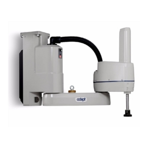
adept technology Cobra s800 User Manual (152 pages)
Robot
Brand:
adept technology
| Category:
Robotics
| Size: 4.2 MB
Table of Contents
Table of Contents
5
Introduction
15
Product Description
15
Adept Cobra S600/S800 Robots
15
Figure 1-1. Adept Cobra S800 Robot
15
Adept Smartamp AIB
16
Figure 1-2. Robot Joint Motions
16
Figure 1-3. Adept Smartamp AIB
16
Adept Smartcontroller
17
Adept Smartcontroller CX
17
Sdio Module
17
Figure 1-4. Adept Smartcontroller CX
17
Installation Overview
18
Manufacturer's Declaration
18
How Can I Get Help
19
Related Manuals
19
Adept Document Library
19
Safety
21
Dangers, Warnings, Cautions, and Notes in Manual
21
Warning Labels on the Robot
22
Figure 2-1. Electrical and Thermal Warning Labels on AIB Chassis
22
Figure 2-2. Thermal Warning Label on Underside of Inner Link
22
Precautions and Required Safeguards
23
Figure 2-3. Warning Label on Encoder Cables
23
Safety Barriers
24
Front Panel Location
24
Impact and Trapping Points
24
Instructions for Emergency Movement Without Drive Power
24
Emergency Recovery Procedures
24
Additional Safety Information
25
Risk Assessment
26
Exposure
27
Severity of Injury
27
Avoidance
27
Slow Speed Control Function and Testing
28
Control System Behavior Category
28
Intended Use of the Robots
28
Robot Modifications
30
Acceptable Modifications
30
Unacceptable Modifications
30
Transport
30
Safety Requirements for Additional Equipment
31
Sound Emissions
31
2.10 Thermal Hazard
31
2.11 Working Areas
32
2.12 Qualification of Personnel
32
2.13 Safety Equipment for Operators
33
2.14 Protection against Unauthorized Operation
33
2.15 Safety Aspects While Performing Maintenance
33
2.16 Risks Due to Incorrect Installation or Operation
34
2.17 What to Do in an Emergency
34
Robot Installation
35
Transport and Storage
35
Figure 3-1. Cobra S600/S800 Robot on a Transportation Pallet
35
Unpacking and Inspecting the Adept Equipment
36
Before Unpacking
36
Upon Unpacking
36
Repacking for Relocation
36
Environmental and Facility Requirements
37
Mounting the Robot
37
Mounting Surface
37
Robot Mounting Procedure
38
Figure 3-2. Mounting Hole Pattern for Robot
38
Description of Connectors on Robot Interface Panel
40
Figure 3-3. Robot Interface Panel
40
System Installation
41
System Cable Diagram
41
Figure 4-1. System Cable Diagram for Adept Cobra S600/S800 Robots
41
Cable and Parts List
42
Installing the Smartcontroller
42
Cable Connections from Robot to Smartcontroller
43
Connecting 24 VDC Power to Robot
43
Specifications for 24 VDC Power
43
Details for 24 VDC Mating Connector
44
Procedure for Creating 24 VDC Cable
44
Installing 24 VDC Robot Cable
45
Figure 4-2. User-Supplied 24 VDC Cable
45
Connecting 200-240 VAC Power to Robot
46
Specifications for AC Power
46
Facility Overvoltage Protection
47
AC Power Diagrams
48
Details for AC Mating Connector
48
Figure 4-3. Typical AC Power Installation with Single-Phase Supply
48
Figure 4-4. Single-Phase AC Power Installation from a Three-Phase AC Supply
48
Procedure for Creating 200-240 VAC Cable
49
Installing AC Power Cable to Robot
49
Figure 4-5. AC Power Mating Connector
49
Grounding the Adept Robot System
50
Ground Point on Robot Base
50
Robot-Mounted Equipment Grounding
50
Figure 4-6. Ground Point on Robot Base
50
Installing User-Supplied Safety Equipment
51
System Operation
53
Robot Status LED Description
53
Figure 5-1. Robot Status LED Indicator Location
53
Status Panel Fault Codes
54
Figure 5-2. Status Panel
54
Using the Brake Release Button
55
Brakes
55
Brake Release Button
56
Connecting Digital I/O to the System
57
Figure 5-3. Connecting Digital I/O to the System
57
Using Digital I/O on Robot XIO Connector
59
Optional I/O Products
60
XIO Input Signals
60
XIO Input Specifications
60
Typical Input Wiring Example
61
Figure 5-4. Typical User Wiring for XIO Input Signals
61
XIO Output Signals
62
XIO Output Specifications
62
Typical Output Wiring Example
63
XIO Breakout Cable
63
Figure 5-5. Typical User Wiring for XIO Output Signals
63
Figure 5-6. Optional XIO Breakout Cable
63
Commissioning the System
65
Verifying Installation
65
Mechanical Checks
65
System Cable Checks
65
User-Supplied Safety Equipment Checks
66
System Start-Up Procedure
66
Figure 5-7. Typical Startup Screen
66
Verifying E-Stop Functions
67
Verify Robot Motions
67
Learning to Program the Adept Cobra S-Series Robot
67
Maintenance
69
Field-Replaceable Parts
69
Periodic Maintenance Schedule
69
Checking Safety Systems
70
Checking Robot Mounting Bolts
71
Check Robot for Oil Around Harmonic Drive
71
Lubricate Joint 3 Ball Screw
71
Required Grease for the Robot
71
Lubrication Procedure
72
Figure 6-1. Lubrication of Joint 3 Quill
73
Replacing the Smartamp AIB Chassis
74
Removing the Smartamp AIB Chassis
74
Figure 6-2. Securing Screw on Smartamp AIB Chassis
74
Figure 6-3. Opening and Removing AIB Chassis
75
Figure 6-4. Connectors on AIB Chassis
75
Installing a New Smartamp AIB Chassis
76
Figure 6-5. Ground Screw on AIB Chassis
76
Figure 6-6. Installing AIB Chassis in Robot Base
77
Replacing the Encoder Battery
78
Battery Replacement Time Periods
78
Battery Replacement Procedure
78
Figure 6-7. Location of Encoder Battery
79
Optional Equipment Installation
81
Installing End-Effectors
81
Removing and Installing the Tool (User) Flange
81
Removing the Flange
81
Installing the Flange
82
Figure 7-1. Tool Flange Removal Details
82
User Connections on Robot
83
User Air Lines
83
User Electrical Lines
83
Figure 7-2. User Connectors on Joint 1
83
Figure 7-3. User Connectors on Joint 2
83
Internal User Connectors
84
Figure 7-4. Internal User Connectors - OP3/4, EOAPWR, ESTOP
84
Figure 7-5. SOLND Connector
84
SOLND Connector
85
OP3/4 Connector
85
EOAPWR Connector
86
Figure 7-6. OP3/4 and SOLND Circuits
86
Internal User Connector Output Specifications
87
ESTOP Connector
88
Procedure to Enable Breakaway E-Stop Function
88
Figure 7-7. Internal E-Stop Connector Circuit
88
Mounting Locations for External Equipment
89
Installing Robot Solenoid Kit
90
Introduction
90
Tools Required
90
Procedure
90
Figure 7-8. Solenoid Mounting Bracket with Connector and Spare Air Line
91
Figure 7-9. Solenoid Placement Using Mounting Hardware
92
Figure 7-10. Removing the Cable Strap Plate
92
Figure 7-11. Connecting Spare Air Line to User Connector
93
Robot Camera Bracket Kit
94
Introduction
94
Tools Required
94
Procedure
94
Devicenet Communication Link
95
Figure 7-12. Mounting a Camera on the Robot
95
Recommended Vendors for Mating Cables and Connectors
96
Figure 7-13. Micro-Style Connector Pinouts for Devicenet
96
Installing Adjustable Hardstops
97
Joint 1 Adjustable Hardstops
97
Installation Procedure
97
Modifying Joint Limit Softstop Locations for Joint 1
97
Figure 7-14. Joint 1 Adjustable Hardstops
97
Figure 7-15. SPEC Program Main Menu
98
Figure 7-16. Robot Specs Menu
98
Figure 7-17. Joint 1 Motion Parameters Menu
99
Figure 7-18. Joint 1 Menu - Lower Limits
99
Joint 2 Adjustable Hardstops
100
Figure 7-19. Joint 1 Menu - Upper Limits
100
Figure 7-20. Joint 2 Hardstop Kit
100
Installation Procedure
101
Figure 7-21. Joint 2 Adjustable Hardstop Locations
101
Figure 7-22. Screw Locations for Joint 2 Adjustable Hardstops
101
Modifying Joint Limit Softstop Locations for Joint 2
102
Figure 7-23. Fixed Hardstop Device for Joint 2
102
Figure 7-24. Joint 2 Motion Parameters Menu
103
Figure 7-25. Joint 2 Menu - Lower Limits
103
Figure 7-26. Joint 2 Menu - Upper Limits
104
Technical Specifications
105
Dimension Drawings
105
Figure 8-1. Adept Cobra S600 Robot Top and Side Dimensions
105
Figure 8-2. Adept Cobra S800 Robot Top and Side Dimensions
106
Figure 8-3. Dimensions of the Camera Bracket Mounting Pattern
107
Figure 8-4. Tool Flange Dimensions for Adept Cobra Robots
108
Figure 8-5. External Tooling on Top of Robot Arm
109
Figure 8-6. External Tooling on Underside of Outer Link
110
Figure 8-7. Adept Cobra S600 Robot Working Envelope
111
Figure 8-8. Adept Cobra S800 Robot Working Envelope
112
Cobra S600/S800 Internal Connections
113
XSLV Connector
113
Figure 8-9. Adept Cobra S600/S800 Internal Connections Diagram
113
Robot Specifications
114
Cleanroom Robots
117
Cobra S600/S800 Cleanroom Option
117
Introduction
117
Specifications
117
Figure 9-1. Adept Cobra S600 Cleanroom Robot
117
Connections
118
Requirements
118
Figure 9-2. Cleanroom Connections
118
Exclusions and Incompatibilities
119
Maintenance
119
Bellows Replacement
119
Lubrication
120
Figure 9-3. Cleanroom Bellows Replacement
120
10.1 Cobra S800 IP-65 Classification
121
Figure 10-1. Adept Cobra S800 Robot - IP-65 Version
121
10.2 Installing Cable Seal Assembly
122
Cable Seal Identification
122
Installation Procedure
122
Figure 10-2. Cable Seal Parts
122
Figure 10-3. Cable Seal Housing Installed
122
Figure 10-4. Installing Lower Flange
123
Figure 10-5. Lower Flange in Position
123
Figure 10-6. Upper Flange Installed
123
Figure 10-7. Splash Guard Installed
123
10.3 Robot Outer Link Cover Removal and Replacement
124
Cover Removal Procedure
124
Figure 10-8. Cover Removal Instructions
124
Cover Replacement Procedure
125
Figure 10-9. IP-65 Robot with Outer Link Cover Removed
125
10.4 Customer Requirements
126
Sealing the Tool Flange
126
Figure 10-10. Cobra IP-65 Tool Flange
126
Pressurizing the Robot
127
Figure 10-11. Compressed Air Fitting on Robot
127
10.5 User Connectors
128
User Electrical and Devicenet
128
Figure 10-12. User Connectors on Joint 1 Cover
128
Figure 10-13. IP-65 Internal Connectors with Outer Link Cover Removed
128
User Air Lines
129
Robot Solenoid Option
129
10.6 Maintenance
129
IP-65 Bellows Replacement
129
Figure 10-14. Bellows Replacement
130
Figure 10-15. Bellows Clamp Alignment
130
10.7 Dimension Drawing for Cable Seal Assembly
131
Figure 10-16. Cable Seal Assembly Dimensions
131
Dual Robot Systems
133
11.1 System Installation
133
Figure 11-1. Dual Robot System Cable Diagram
133
11.2 System Configuration
134
Connecting Digital I/O to a Dual Robot System
135
Figure 11-2. Digital I/O Connections to a Dual Robot System
135
11.4 Digital I/O Block Configuration
137
XIO Inputs/Outputs
137
XIO Outputs
137
XIO Inputs
137
Internal Robot Outputs
137
IO Blox Inputs/Outputs
137
Sdio Inputs/Outputs
137
Figure 11-3. Input/Output Block Configuration in Dual Robot Systems
138
Figure 11-4. Input/Output Block Configuration for Optional Sdio Modules
139
11.5 Using CONFIG_C to Configure I/O
140
IO Configuration by Editing System File
140
Figure 11-5. CONFIG_C Menu
140
Figure 11-6. Controller Configuration Editor Menu
141
Figure 11-7. System Configuration Editor Menu
141
Figure 11-8. Sample Configuration File for Digital I/O
142
IO Configuration by Importing Pre-Configured File
143
11.6 System Startup Procedure
143
11.7 Operation with the Adept T1/T2 pendant
144
11.8 Programming Information
144
Language Programming
144
Monitor Commands
144
11.9 Emergency Stop Circuit Shuts off both Robots
145
Index
147
Advertisement
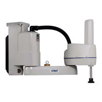
adept technology Cobra s800 User Manual (156 pages)
Inverted Robot
Brand:
adept technology
| Category:
Robotics
| Size: 4.72 MB
Table of Contents
Table of Contents
5
Introduction
15
Product Description
15
Adept Cobra S800 Inverted Robots
15
Figure 1-1. Adept Cobra S800 Inverted Robot
15
Adept Smartamp AIB
16
Figure 1-2. Robot Joint Motions
16
Adept Smartcontroller
17
Figure 1-3. Adept Smartamp AIB (Standard Version Shown)
17
Sdio Module
18
Installation Overview
18
Figure 1-4. Adept Smartcontroller CX
18
Manufacturer's Declaration
19
How Can I Get Help
19
Related Manuals
19
Adept Document Library
20
Safety
21
Dangers, Warnings, Cautions, and Notes in Manual
21
Warning Labels on the Robot
22
Figure 2-1. Electrical and Thermal Warning Labels on AIB Chassis
22
Figure 2-2. Thermal Warning Label on Underside of Inner Link
22
Precautions and Required Safeguards
23
Figure 2-3. Warning Label on Encoder Cables
23
Safety Barriers
24
Impact and Trapping Points
24
Instructions for Emergency Movement Without Drive Power
24
Emergency Recovery Procedures
24
Additional Safety Information
25
Risk Assessment
26
Exposure
27
Severity of Injury
27
Avoidance
27
Slow Speed Control Function and Testing
27
Control System Behavior Category
28
Intended Use of the Robots
28
Robot Modifications
29
Acceptable Modifications
29
Unacceptable Modifications
30
Transport
30
Safety Requirements for Additional Equipment
30
Sound Emissions
31
2.10 Thermal Hazard
31
2.11 Working Areas
31
2.12 Qualification of Personnel
32
2.13 Safety Equipment for Operators
33
2.14 Protection against Unauthorized Operation
33
2.15 Safety Aspects While Performing Maintenance
33
2.16 Risks Due to Incorrect Installation or Operation
33
2.17 What to Do in an Emergency Situation
34
Robot Installation
35
Transport and Storage
35
Figure 3-1. Robot on a Transportation Pallet
35
Unpacking and Inspecting the Adept Equipment
36
Before Unpacking
36
Upon Unpacking
36
Repacking for Relocation
36
Environmental and Facility Requirements
37
Mounting the Robot
37
Mounting Surface
37
Mounting Procedure
38
Figure 3-2. Robot Mounting Dimensions
38
Figure 3-3. Robot in Folded Position
38
Figure 3-4. Robot on a Transportation Pallet
39
Connectors on Robot Interface Panel
40
Figure 3-5. Robot Interface Panel
40
System Installation
43
System Cable Diagram
43
Figure 4-1. System Cable Diagram
43
Cable and Parts List
44
Installing the Smartcontroller
44
Cable Connections from Robot to Smartcontroller
45
Connecting 24 VDC Power to Robot
45
Specifications for 24 VDC Power
45
Details for 24 VDC Mating Connector
46
Creating 24 VDC Cable
46
Installing 24 VDC Robot Cable
47
Figure 4-2. User-Supplied 24 VDC Cable
47
Connecting 200-240 VAC Power to Robot
48
Specifications for AC Power
48
Facility Overvoltage Protection
49
AC Power Diagrams
49
Figure 4-3. Typical AC Power Installation with Single-Phase Supply
49
Details for AC Mating Connector
50
Creating 200-240 VAC Cable
50
Figure 4-4. Single-Phase AC Power Installation from a Three-Phase AC Supply
50
Installing AC Power Cable to Robot
51
Grounding the Robot
51
Ground Point on Robot Base
51
Figure 4-5. AC Power Mating Connector
51
Robot-Mounted Equipment Grounding
52
Installing User-Supplied Safety Equipment
52
Figure 4-6. Ground Point on Robot Base (Standard Robot Shown)
52
System Operation
53
Robot Status LED Description
53
Figure 5-1. Robot Status LED Indicator Location
53
Status Panel Fault Codes
54
Figure 5-2. Status Panel
54
Using the Brake Release Button
55
Brakes
55
Brake Release Button
56
Connecting Digital I/O to the System
56
Figure 5-3. Connecting Digital I/O to the System
57
Using Digital I/O on Robot XIO Connector
59
Optional I/O Products
60
XIO Input Signals
60
XIO Input Specifications
60
Typical Input Wiring Example
61
Figure 5-4. Typical User Wiring for XIO Input Signals
61
XIO Output Signals
62
XIO Output Specifications
62
Typical Output Wiring Example
63
XIO Breakout Cable
63
Figure 5-5. Typical User Wiring for XIO Output Signals
63
Figure 5-6. Optional XIO Breakout Cable
63
Commissioning the System
65
Verifying Installation
65
Mechanical Checks
65
System Cable Checks
65
User-Supplied Safety Equipment Checks
66
System Start-Up Procedure
66
Figure 5-7. Typical Start-Up Screen
66
Verifying E-Stop Functions
67
Verify Robot Motions
67
Learning to Program the Robot
67
Optional Equipment Installation
69
Installing End-Effectors
69
Removing and Installing the User Flange
69
Removing the Flange
69
Installing the Flange
70
User Connections on Robot
70
User Air Lines
70
Figure 6-1. User Flange Removal Details
70
Figure 6-2. User Connector Panel, Standard Version
71
Figure 6-3. User Connector Panel, IP-65 Version
71
User Electrical Lines
72
Internal User Connectors
72
Figure 6-4. User Connectors on Standard Joint 2. IP-65 Joint 2 on Right
72
Figure 6-5. Internal User Connectors - OP3/4, EOAPWR, ESTOP
73
Figure 6-6. SOLND Connector
73
SOLND Connector
74
OP3/4 Connector
74
EOAPWR Connector
75
Internal User Connector Output Specifications
75
Figure 6-7. OP3/4 and SOLND Circuits
75
ESTOP Connector
76
Procedure to Enable Breakaway E-Stop Function
77
Mounting Locations for External Equipment
77
Figure 6-8. Internal E-Stop Connector Circuit
77
Installing Robot Solenoid Kit
78
Introduction
78
Tools Required
78
Procedure
78
Figure 6-9. Solenoid Mounting Bracket with Connector and Spare Air Line
79
Figure 6-10. Solenoid Placement Using Mounting Hardware
80
Figure 6-11. Connecting Spare Air Line to User Connector
80
Installing Camera Bracket Kit
81
Introduction
81
Tools Required
82
Procedure
82
Figure 6-12. Mounting a Camera on the Robot
82
Devicenet Communication Link
83
Recommended Vendors for Mating Cables and Connectors
84
Installing Adjustable Hardstops
84
Joint 1 Adjustable Hardstops
84
Figure 6-13. Micro-Style Connector Pinouts for Devicenet
84
Installing
85
Modifying Joint Limit Softstop Locations for Joint 1
85
Figure 6-14. Joint 1 Adjustable Hardstops
85
Figure 6-15. SPEC Program Main Menu
86
Figure 6-16. Robot Specs Menu
86
Figure 6-17. Joint 1 Motion Parameters Menu
87
Figure 6-18. Joint 1 Menu - Lower Limit
87
Joint 2 Adjustable Hardstops
88
Figure 6-19. Joint 1 Menu - Upper Limits
88
Figure 6-20. Joint 2 Hardstops
88
Installation Procedure
89
Figure 6-21. IP-65 Arcs
89
Figure 6-22. Joint 2 Adjustable Hardstop Locations
90
Figure 6-23. Screw Locations for Joint 2 Adjustable Hardstops
90
Modifying Joint Limit Softstop Locations for Joint 2
91
Figure 6-24. Fixed Hardstop Block for Joint 2
91
Figure 6-25. Joint 2 Motion Parameters Menu
92
Figure 6-26. Joint 2 Menu - Lower Limits
92
Figure 6-27. Joint 2 Menu - Upper Limits
93
IEC IP-65 Classification
95
Figure 7-1. Adept Cobra S800 Robot - IP-65 Version
95
Modifications to Meet IP-65 Classification
96
Outer Link
96
AIB Cable Seal
96
Controller
96
Hard Stop, Rotation Range
96
AIB Cable Seal Overview
96
Removing/Installing the Cable Entry Housing
97
Figure 7-2. IP-65 Cable Entry Housing
97
Removing the Cable Entry Housing Cover
98
Figure 7-3. Exploded View of Cable Entry Housing/Seal Assembly
98
Figure 7-4. Cable Entry Housing with Cover Removed
99
Installing the Cable Entry Housing Cover
100
Removing the Cable Entry Housing Body
100
Installing the Cable Entry Housing Body
100
Removing/Installing Outer Link Cover
100
Removing Outer Link Cover
100
Figure 7-5. Cover Removal Instructions
101
Installing Outer Link Cover
102
Figure 7-6. IP-65 Robot with Outer Link Cover Removed
102
Customer Requirements
103
Sealing the Tool Flange
103
Figure 7-7. IP-65 Tool Flange
103
Pressurizing the Robot
104
Figure 7-8. Compressed Air Fitting on Robot
104
User Connectors
105
User Electrical and Devicenet
105
User Air Lines
105
Figure 7-9. User Connectors on Robot Base (Capped/Covered)
105
Figure 7-10. IP-65 Internal Connectors with Outer Link Cover Removed
105
Robot Solenoid Option
106
Maintenance
106
Replacing IP-65 Bellows
106
Installing the Roxtec Cable Seal Assembly
107
Figure 7-11. Bellows
107
Figure 7-12. Bellows Clamps, Gaskets
107
Figure 7-13. Exploded View of Roxtec Assembly
108
7.10 Removing the Roxtec Cable Seal Assembly
111
Maintenance
113
Periodic Maintenance Schedule
113
Checking Safety Systems
114
Checking Robot Mounting Bolts
114
Checking for Oil Around Harmonic Drive
114
Lubricating Joint 3 Ball Screw
115
Figure 8-1. Lubrication of Joint 3 Quill
116
Replacing the Smartamp AIB Chassis
117
Removing the Smartamp AIB Chassis
117
Figure 8-2. Securing Screw on Smartamp AIB Chassis
117
Figure 8-3. Opening and Removing AIB Chassis
118
Figure 8-4. Support Bolt Hole
118
Figure 8-5. AIB Hanging from Support Bolt
119
Figure 8-6. Connectors on AIB Chassis
119
Figure 8-7. Ground Screw on AIB Chassis
120
Installing a New Smartamp AIB Chassis
121
Figure 8-8. Installing AIB Chassis in Robot Base
121
Replacing the Encoder Battery
122
Battery Replacement Time Periods
122
Battery Replacement Procedure
122
Installing the Encoder Battery in the Inner Link
123
Figure 8-9. Location of Encoder Battery
123
Figure 8-10. Location of Encoder Battery Cable in Inner Link
124
Technical Specifications
125
Dimension Drawings
125
Figure 9-1. Top and Side Dimensions
125
Figure 9-2. IP-65 Top and Side Dimensions
126
Figure 9-3. Dimensions of the Camera Bracket Mounting Pattern
127
Figure 9-4. Tool Flange Dimensions
128
Figure 9-5. External Tooling on Top of Robot Arm
129
Figure 9-6. External Tooling on Underside of Outer Link
130
Figure 9-7. Standard Robot Working Envelope
131
Figure 9-8. IP-65 Robot Working Envelope
131
Cobra S800 Inverted Robot Internal E-STOP Connections
132
Figure 9-9. Internal E-STOP Connections Diagram
132
XSLV Connector
133
Robot Specifications
134
Dual Robot Systems
137
10.1 System Installation
137
Figure 10-1. Dual Robot System Cable Diagram
137
10.2 System Configuration
138
10.3 Connecting Digital I/O to a Dual Robot System
139
Figure 10-2. Digital I/O Connections to a Dual Robot System
139
10.4 Digital I/O Block Configuration
141
XIO Inputs/Outputs
141
XIO Outputs
141
XIO Inputs
141
Internal Robot Outputs
141
IO Blox Inputs/Outputs
141
Sdio Inputs/Outputs
141
Figure 10-3. Input/Output Block Configuration in Dual Robot Systems
142
Figure 10-4. Input/Output Block Configuration for Optional Sdio Modules
143
10.5 Using CONFIG_C to Configure I/O
144
IO Configuration by Editing System File
144
Figure 10-5. CONFIG_C Menu
144
Figure 10-6. Controller Configuration Editor Menu
145
Figure 10-7. System Configuration Editor Menu
145
Figure 10-8. Sample Configuration File for Digital I/O
146
IO Configuration by Importing Pre-Configured File
147
10.6 System Startup Procedure
147
10.7 Operating with an Adept pendant
148
10.8 Programming Information
148
Language Programming
148
Monitor Commands
148
10.9 Emergency Stop Circuit
149
Index
151
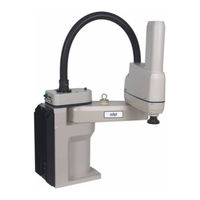
adept technology Cobra s800 User Manual (140 pages)
Inverted Robot
Brand:
adept technology
| Category:
Robotics
| Size: 8.23 MB
Table of Contents
Table of Contents
5
Chapter 1: Introduction
11
Product Description
11
Adept Cobra S800 Inverted™ Robots
11
Adept AIB™, Eaib
12
Adept Smartcontroller
13
Dangers, Warnings, Cautions, and Notes in Manual
14
Safety Precautions
15
What to Do in an Emergency Situation
15
Additional Safety Information
15
Manufacturer's Declaration of Compliance (MDOC)
16
Adept Robot Safety Guide
16
Intended Use of the Robots
16
Installation Overview
16
Manufacturer's Declaration
17
How Can I Get Help
17
Related Manuals
18
Adept Document Library
18
Chapter 2: Robot Installation
19
Transport and Storage
19
Unpacking and Inspecting the Adept Equipment
20
Before Unpacking
20
Upon Unpacking
20
Repacking for Relocation
20
Environmental and Facility Requirements
20
Mounting the Robot
21
Mounting Surface
21
Mounting Procedure
22
Connectors on Robot Interface Panel
24
Chapter 3: System Installation
27
System Cable Diagram
27
Cable and Parts List
28
Installing the Smartcontroller
28
Connecting User-Supplied PC to Robot
29
PC Requirements
29
Installing Adept ACE Software
29
Cable Connections from Robot to Smartcontroller
30
Connecting 24 VDC Power to Robot
31
Specifications for 24 VDC Power
31
Details for 24 VDC Mating Connector
31
Creating 24 VDC Cable
32
Installing 24 VDC Robot Cable
32
Connecting 200-240 VAC Power to Robot
33
Specifications for AC Power
34
Details for AC Mating Connector
36
Creating the 200-240 VAC Cable
36
Installing AC Power Cable to Robot
37
Grounding the Adept Robot System
37
Ground the Robot Base
37
Grounding Robot-Mounted Equipment
38
Installing User-Supplied Safety Equipment
38
Chapter 4: System Operation
39
Robot Status LED Description
39
Status Panel Fault Codes
40
Brakes
41
Programmable E-Stop Delay
41
Brake Release Button
42
Front Panel
42
Connecting Digital I/O to the System
43
Using Digital I/O on Robot XIO Connector
45
Optional I/O Products
46
XIO Input Signals
46
XIO Output Signals
48
XIO Breakout Cable
50
Starting the System for the First Time
52
Verifying Installation
52
Turning on Power and Starting Adept ACE
53
Enabling High Power
54
Verifying E-Stop Functions
54
Verify Robot Motions
54
Learning to Program the Robot
54
Chapter 5: Maintenance
55
Field-Replaceable Parts
55
Periodic Maintenance Schedule
55
Checking Safety Systems
56
Checking Robot Mounting Bolts
56
Checking for Oil Around Harmonic Drives
57
Lubricating Joint 3 Ball Screw
57
Lubrication Procedure
57
Replacing the AIB or Eaib Chassis
60
Removing the AIB or Eaib Chassis
60
Installing a New AIB or Eaib Chassis
64
Commissioning a System with an Eaib
65
Safety Commissioning Utilities
65
E-Stop Configuration Utility
67
E-Stop Verification Utility
68
Teach Restrict Configuration Utility
68
Teach Restrict Verification Utility
69
Replacing the Encoder Battery Pack
70
Battery Replacement Time Periods
71
Battery Replacement Procedure
71
Installing an Encoder Battery in the Inner Link
72
Chapter 6: Optional Equipment Installation
75
Installing End-Effectors
75
Removing and Installing the Tool Flange
75
Removing the Flange
75
Installing the Flange
76
User Connections on Robot
76
User Air Lines
76
User Electrical Lines
78
Internal User Connectors
78
SOLND Connector
80
OP3/4 Connector
80
EOAPWR Connector
81
Internal User Connector Output Specifications
82
ESTOP Connector
82
Mounting Locations for External Equipment
84
Installing Robot Solenoid Kit
85
Introduction
85
Tools Required
86
Procedure
86
Installing Camera Bracket Kit
90
Introduction
90
Tools Required
90
Procedure
90
Devicenet Communication Link
91
Recommended Vendors for Mating Cables and Connectors
93
Installing Adjustable Hardstops
94
Joint 1 Adjustable Hardstops
94
Joint 2 Adjustable Hardstops
98
Chapter 7: Technical Specifications
105
Dimension Drawings
105
Cobra S800 Inverted Robot Internal E-STOP Connections
112
XSYS/XSYSTEM Connector
112
XSLV Connector
113
Robot Specifications
113
Chapter 8: Cleanroom Robots
117
Cobra S800 Inverted Cleanroom Option
117
Introduction
117
Connections
118
Requirements
118
Exclusions and Incompatibilities
119
Maintenance
119
Bellows Replacement
119
Lubrication
120
Chapter 9: IP-65 Option
121
IEC IP-65 Classification
121
Modifications to Meet IP-65 Classification
122
Outer Link
122
Aib/Eaib Cable Seal
122
Controller
122
Hard Stop, Rotation Range
122
Aib/Eaib Cable Seal Overview
122
Removing/Installing the Cable Entry Housing
122
Removing the Cable Entry Housing Cover
124
Installing the Cable Entry Housing Cover
126
Removing the Cable Entry Housing Body
126
Installing the Cable Entry Housing Body
126
Removing/Installing Outer Link Cover
126
Removing Outer Link Cover
126
Installing Outer Link Cover
128
Customer Requirements
129
Sealing the Tool Flange
129
Pressurizing the Robot
130
User Connectors
131
User Electrical and Devicenet
131
User Air Lines
132
Robot Solenoid Option
132
Maintenance Replacing IP-65 Bellows
132
Installing the Roxtec Cable Seal Assembly
133
Removing the Roxtec Cable Seal Assembly
138
Advertisement
adept technology Cobra s800 User Manual (126 pages)
Brand:
adept technology
| Category:
Robotics
| Size: 7.17 MB
Table of Contents
Table of Contents
5
Chapter 1: Introduction
9
Product Description
9
Adept Cobra S600/S800™ Robots
9
AIB™, Eaib™ (Amplifiers in Base)
10
Adept Smartcontroller
11
Dangers, Warnings, Cautions, and Notes
12
Safety Precautions
13
What to Do in an Emergency Situation
13
Additional Safety Information
13
Manufacturer's Declaration of Conformity (MDOC)
13
Adept Robot Safety Guide
14
Intended Use of the Robots
14
Installation Overview
14
Manufacturer's Declaration
15
How Can I Get Help
15
Related Manuals
15
Adept Document Library
16
Chapter 2: Robot Installation
17
Transport and Storage
17
Unpacking and Inspecting the Adept Equipment
18
Before Unpacking
18
Upon Unpacking
18
Repacking for Relocation
18
Environmental and Facility Requirements
18
Mounting the Robot
19
Mounting Surface
19
Robot Mounting Procedure
20
Description of Connectors on Robot Interface Panel
21
Chapter 3: System Installation
23
System Cable Diagram
23
Cable and Parts List
24
Installing the Smartcontroller
24
Connecting User-Supplied PC to Smartcontroller
25
PC Requirements
25
Installing Adept ACE Software
25
Cable Connections from Robot to Smartcontroller
25
Connecting 24 VDC Power to Robot
26
Specifications for 24 VDC Power
26
Details for 24 VDC Mating Connector
27
Procedure for Creating 24 VDC Cable
28
Installing 24 VDC Robot Cable
28
Connecting 200-240 VAC Power to Robot
29
Specifications for AC Power
30
Details for AC Mating Connector
32
Creating the 200-240 VAC Cable
32
Installing AC Power Cable to Robot
33
Grounding the Adept Robot System
33
Grounding the Robot Base
33
Grounding Robot-Mounted Equipment
34
Installing User-Supplied Safety Equipment
34
Chapter 4: System Operation
35
Robot Status LED Description
35
Status Panel Fault Codes
35
Brakes
37
Programmable E-Stop Delay
37
Brake Release Button
37
Front Panel
38
Connecting Digital I/O to the System
39
Using Digital I/O on Robot XIO Connector
41
Optional I/O Products
42
XIO Input Signals
42
XIO Output Signals
44
XIO Breakout Cable
46
Starting the System for the First Time
48
Verifying Installation
48
Turning on Power
49
Starting Adept ACE
50
Enabling High Power
50
Verifying E-Stop Functions
50
Verify Robot Motions
51
Learning to Program the Adept Cobra S-Series Robot
51
Chapter 5: Maintenance
53
Field-Replaceable Parts
53
Periodic Maintenance Schedule
53
Checking Safety Systems
54
Checking Robot Mounting Bolts
54
Checking Robot for Oil Around Harmonic Drive
54
Lubricating Joint
55
Lubrication Procedure
55
Replacing the AIB or Eaib Chassis
58
Removing the AIB or Eaib Chassis
58
Installing a New AIB or Eaib Chassis
60
Commissioning a System with an Eaib
62
Safety Commissioning Utilities
62
E-Stop Configuration Utility
64
E-Stop Verification Utility
64
Teach Restrict Configuration Utility
65
Teach Restrict Verification Utility
65
Replacing the Encoder Battery Pack
66
Battery Replacement Time Periods
67
Battery Replacement Procedure
67
Chapter 6: Optional Equipment Installation
69
Installing End-Effectors
69
Removing and Installing the Tool Flange
69
Removing the Flange
69
Installing the Flange
70
User Connections on Robot
70
User Air Lines
70
User Electrical Lines
71
Internal User Connectors
71
SOLND Connector
73
OP3/4 Connector
73
EOAPWR Connector
74
Internal User Connector Output Specifications
74
ESTOP Connector
75
Mounting Locations for External Equipment
77
Installing the Robot Solenoid Kit
77
Tools Required
79
Procedure
79
Installing the Camera Bracket Kit
83
Tools Required
83
Procedure
83
Devicenet Communication Link
84
Recommended Vendors for Mating Cables and Connectors
86
Installing Adjustable Hardstops
86
Joint 1 Adjustable Hardstops
87
Joint 2 Adjustable Hardstops
91
Chapter 7: Technical Specifications
99
Dimension Drawings
99
Cobra S600/S800 Robot Internal E-STOP Connections
105
XSYS/XSYSTEM Connector
105
XSLV Connector
106
Robot Specifications
106
Chapter 8: IP-65 Option
109
Cobra S800 IP-65 Classification
109
Installing Cable Seal Assembly
109
Cable Seal Identification
109
Installation Procedure
110
Robot Outer Link Cover Removal and Reinstallation
111
Cover Removal Procedure
112
Cover Reinstallation Procedure
113
Customer Requirements
114
Sealing the Tool Flange
114
Pressurizing the Robot
114
User Connectors
115
User Electrical and Devicenet
115
User Air Lines
116
Robot Solenoid Option
117
Maintenance
117
Bellows Replacement
117
Dimension Drawing for Cable Seal Assembly
119
Chapter 9: Cleanroom Robots
121
Cleanroom Specifications
121
Connections
122
Requirements
122
Exclusions and Incompatibilities
122
Cleanroom Maintenance
123
Bellows Replacement
123
Lubrication
123
Advertisement
Related Products
adept technology AdeptViper s650
adept technology AdeptViper s850
adept technology Quattro s650H
adept technology Quattro s650HS
adept technology Quattro s800H
adept technology Quattro s800HS
adept technology Cobra s600
adept technology Cobra s350
adept technology Cobra Dual
adept technology SmartController EX
adept technology Categories
Robotics
Controller
Control Unit
Network Router
Thermostat
More adept technology Manuals
Login
Sign In
OR
Sign in with Facebook
Sign in with Google
Upload manual
Upload from disk
Upload from URL