Advertisement
Available languages
Available languages
Quick Links
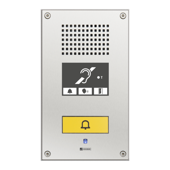
SIP station SIP-WS 211V DA with induction loop
Dimensions and recommended mounting height
Measuring units in mm (in), not to scale! Front panel thickness: 3 mm (0.12 in)
160 (6.3)
140 (5.5)
Extent of supply
• SIP station
• Induction loop and mounting kit
• Mounting screws (4 x Torx TR 25 security countersunk screws, M5x10)
• Short reference
Cleaning instructions
The device may only be cleaned with cleaning agents for stainless steel. Do not use cleaning agents
containing chlorine or isopropanol.
Safety warnings
• This device shall be installed or replaced by trained and qualified personnel only.
• Do not install the device on unstable walls or on surfaces, which cannot support the device's weight.
• Only use recommended tools when installing the device.
• Only accessories that comply with the device's technical specifications shall be used.
• All connected circuits shall fulfil the requirements for Safety Extra Low Voltage (SELV) and Limited
Power Source (LPS) according to IEC/EN 60950-1.
• Use shielded Ethernet cables only.
• Before using the device, ensure all cables are correctly connected and not damaged.
• Disconnect the power supply (PoE or DC) for any maintenance of the device.
• Allow the device to cool down completely before touching parts inside.
• Do not make any unauthorised modifications to the device.
Connection diagram
LED "Power"
External power supply
15 VDC – 26 VDC
DC–
External power supply
24 VDC (± 2 V)
DC+
OUT 2
OUT 2
OUT 2
OUT 1
OUT 1
Finished floor
IP uplink
+ PoE
LED
MLC
Loop
"Adjust"
Current
+
- -
+
- -
LINE IN
Output
Induction loop
External
loudspeaker module
IN 1
MUTE
IN 2
GND
Factory
IN 3
LINE–
Reset
LINE+
GND
button
IP downlink
Mounting clip
Induction loop
Surface or flush mount kit
Advertisement

Related Manuals for Commend SIP-WS 211V DA


Summary of Contents for Commend SIP-WS 211V DA
- Page 1 SIP station SIP-WS 211V DA with induction loop Connection diagram Dimensions and recommended mounting height Measuring units in mm (in), not to scale! Front panel thickness: 3 mm (0.12 in) 160 (6.3) 140 (5.5) Mounting clip Loop “Adjust” Current LED “Power”...
- Page 2 • The restriction of the use of certain hazardous substances in electrical and electronic equipment (directive 2011/65/EU) For technical data and configuration, see the respective manual. Keep this description in safe custody. Type: D-BZ-SIPWS211VDA, Version: 2.2/1117 Commend International GmbH, Saalachstraße 51, A-5020 Salzburg – www.commend.com/sip...
- Page 3 SIP-Sprechstelle SIP-WS 211V DA mit Induktionsschleife Anschlussdiagramm Abmessungen und empfohlene Montagehöhe Maße in mm, kein Maßstab! Frontplattenstärke: 3 mm Montageschelle Loop „Adjust“ Current LED „Power“ Induktionsschleife LINE IN Externe Spannungsversorgung Induktions- 15 VDC – 26 VDC schleifen- ausgang Externe DC–...
- Page 4 • Beschränkung der Verwendung bestimmter gefährlicher Stoffe in Elektro- und Elektronikgeräten (Richtlinie 2011/65/EU) Technische Daten und Konfigurationsanweisungen sind im entsprechenden Manual zu finden. Bewahren Sie diese Beschreibung sorgfältig auf. Type: D-BZ-SIPWS211VDA, Version: 2.2/1117 Commend International GmbH, Saalachstraße 51, A-5020 Salzburg – www.commend.com/sip...
Need help?
Do you have a question about the SIP-WS 211V DA and is the answer not in the manual?
Questions and answers