Advertisement
Available languages
Available languages
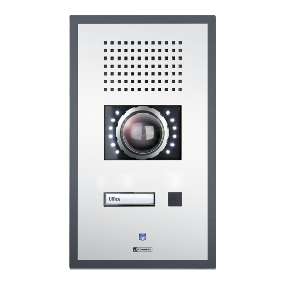
IP Stations WS 201 PICA
Connection
OUT 2
2
OUT2 connection
Expansion bus
OUT 2
OUT 2
OUT 2
OUT 1
Slot for inserting
button label
OUT 1
IP Uplink
IP Downlink
+ PoE
(AXIS Camera
+ PoE)
Camera illuminator control
ƒ By default, the camera illuminator is connected to the main board of the subscriber via
1
the expansion bus. In CCT 800, the device is shown with an additional device EB2E2A.
Use OUT 1 on the EB2E2A to switch the camera illuminator on and off. It is also pos-
sible to use OUT 1 as attendant contact, e.g. to switch the camera illuminator on at
initiation of a call.
ƒ The camera illuminator can also be connected by using OUT 2 of the subscriber. In this
2
case, it is possible to control the camera illuminator via this contact and the expansion
bus can be used for other devices.
For dimming the camera illuminator use the potentiometer
NOTE: It is only possible to use just one relay 2 (OUT 2) connection, i.e. either the screw
terminals or the connector (see connection diagram).
LED brightness
+
3
–
1
IN 1
MUTE
External
GND
IN 2
loudspeaker
module
IN 3
LINE–
GND
LINE+
Handset:
Microphone
Loudspeaker
on the camera board.
3
AXIS electronic module – Control button
Control button
In order to operate the control button, following steps must be performed:
• Loosen screw
(Torx T8)
1
• Turn safety lever
outwards
2
• Push control button
3
• Turn safety lever
back into its original position and tighten the screw
4
The control button can be used for reseting the camera to factory default settings:
• Disconnect power from the camera
• Press and hold the control button
• Keep the control button pressed until the LED indicator
• Release the control button. If the status LED
plete
Attention: After a reset the camera must be re-configured, as the camera image
would otherwise appear 180° upside down.
6
PWR
STAT
4
NET
3
2
2
1
5
and reconnect power
3
flashes amber
4
turns green the process is com-
4
1
Advertisement
Table of Contents

Related Manuals for Commend C-WS201PICA


Summary of Contents for Commend C-WS201PICA
- Page 1 IP Stations WS 201 PICA Connection AXIS electronic module – Control button STAT OUT 2 LED brightness – OUT2 connection Expansion bus OUT 2 OUT 2 OUT 2 OUT 1 Slot for inserting button label OUT 1 Control button In order to operate the control button, following steps must be performed: IN 1 MUTE External...
- Page 2 Measurements / Button Configuration AXIS electronic module – Camera angle / web interface login Measurements in mm (inch), not scale! Depth: 13 (0.51) cavity wall mounting: 15 (0.59) (shadow gap between front panel & wall) 165 (6.5) Finished floor Adjusting the camera First connection In order to adjust the angle of the camera, The IP address is assigned directly via the...
- Page 3 IP-Sprechstelle WS 201PICA Anschluss AXIS-Elektronik-Modul – Steuertaste OUT 2 STAT LED Helligkeit – OUT2 Verbindung Expansion Bus OUT 2 OUT 2 OUT 2 OUT 1 Einschuböffnung für Beschriftungsfelder OUT 1 Steuertaste IN 1 MUTE Externes IN 2 Lautsprecher- Um die Steuertaste betätigen zu können müssen folgende Schritte durchgeführt modul IN 3 LINE–...
- Page 4 Maßzeichnung / Tastenbelegung AXIS-Elektronik-Modul – Kamerawinkel / Webinterface Login Maße in mm, kein Maßstab! Tiefe: 13 bei Hohlwandmontage: 15 ( Schattenfuge zwischen Front u. Wand) Fertige Fussbodenoberfläche Ausrichten der Kamera Erste Verbindung Um den Winkel der Kamera einzustel- Die IP-Adresse wird direkt vom DHCP-Server len, müssen folgende Schritte durchge- vergeben.
Need help?
Do you have a question about the C-WS201PICA and is the answer not in the manual?
Questions and answers