Table of Contents
Advertisement
Advertisement
Table of Contents

Subscribe to Our Youtube Channel
Related Manuals for Commend GE 800


Summary of Contents for Commend GE 800
- Page 1 PRODUCT MANUAL ENGLISH GE 800 MANUAL VERSION 4.2/0617...
- Page 2 GE 800 Manufacturer’s reference: This equipment fulfils the requirements of the EU standard 2014/30/EU (EMC). Therefore, this equipment is CE-labelled. Keep this description in safe custody! Legal notice: The manufacturer guarantees the functionality of its products as described in the data sheets and/or tech- nical documentation.
-
Page 3: Table Of Contents
1. Extent of supply Standard call numbers Dynamic audio channel allocation 2. Additional Components General Technical data Intercom Server basic housing GE 800 Power supply card G8-GEN 3. Assembly of components Processor card G8-GEP Pre-installed plug-in cards Networking card G8-NET... -
Page 4: General Information
General information GE 800 General information PDF format Supported viewers The PDF manual can be used with the following viewers: Adobe Reader from version 6.0 Foxit Reader from version 5.0 Info boxes ATTENTION This information box addresses all necessary configuration options and actions which will allow an error-free operation. -
Page 5: Quick Start
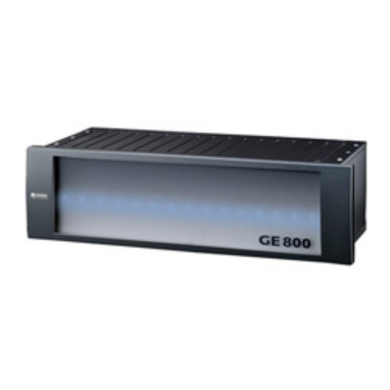
Quick start Intercom Server GE 800 The Intercom Server GE 800 has been designed to meet the internal communication demands of large companies and organisations. With the GE 800, different functions of modern internal communication such as Intercom, video, information and control can be managed within a single system. By means of different subscriber cards with different feature levels and additional interfaces, the Intercom Server can be adapted to the individual needs with ease. -
Page 6: Extent Of Supply
1. Extent of supply GE 800 1. Extent of supply GE 800 Intercom Server 19" housing (3 RU) with snap-on lid G8-GEB bus PCB (with 17 slots, of which 14 are empty) G8-GEN power supply card (incl. G8A-GEN installation board) ... -
Page 7: Additional Components
GE 800 2. Additional Components 2. Additional Components General In addition to the Intercom Server, for start up of the system the following components are required: Subscriber cards: Subscriber cards handle the speech communication as well as subscriber spe- cific functions. -
Page 8: Assembly Of Components
G8-VOIPSERV Max. 100 outputs may be switched on at the same time. For further information, see data sheet “G8-TEL4.” A second slot of the GE 800 is occupied by the G8-V24-PRO delivered with the G8-SELCALL. 4.2/0617... -
Page 9: Installation Of Plug-In Cards
GE 800 3. Assembly of components Installation of plug-in cards Assemble the components as follows: Remove the lid from the housing. Install the installation boards. Insert the plug-in cards into the 19" housing from the front panel side and fix them with the attachment clips. -
Page 10: Installation Boards For Ge 800
3. Assembly of components GE 800 Installation boards for GE 800 The plug-in cards can be used with the following installation boards: Plug-in card G8A-C G8A-CP G8A-I G8A-K G8A-T G8A-V24 G8A-GEN G8A-NET G8A-TEL G8A-PRO G8A-EW G8-16A ... -
Page 11: Cabling
„Connection Intercom Server” „Connection of IP Intercom stations” „Connection of digital and analogue Intercom stations” „Connection inputs and outputs” „Connection of multiple GE 800” Connection Intercom Server Installation board G8A-GEN G8A-GEN Music / alarm input 1..GND (Shield) Floating 2..TXD... -
Page 12: Connection Of Ip Intercom Stations
(switch) via the RJ45 jacks “UPLINK” or “DOWNLINK” on the installation board G8A-NET. G8-NET Switch GE 800 Connection from a GE 800 to a switch NOTE: Configuration For further information about configuration see manual “Intercom Server Configuration”. 4.2/0617... -
Page 13: Connection Of Digital And Analogue Intercom Stations
GE 800 4. Cabling Connection of digital and analogue Intercom stations For digital and analogue Intercom stations, installation boards are required to connect them to the Intercom Server (see page 10). Installation board G8A-C for 4 subscribers 1st subscriber 2nd subscriber... - Page 14 4. Cabling GE 800 Installation board G8A-CP for 4 subscribers Installation board with optional possibility of connecting an additional power supply for digital Inter- com stations via the subscriber line. 1st subscriber Optional at jumper position “PWR”: max. 35 VDC, 1 A...
- Page 15 GE 800 4. Cabling Installation board G8A-T for 8 subscribers Slot n Slot n+1 1st subscriber subscriber whiteblue whiteyellow: A1 blue brown: whiteblue whiteyellow: C1 yellow black: subscriber 2nd subscriber Slot n whiteblue whitegreen: A2 green blue: whiteblue whitegreen: C2...
-
Page 16: Connection Inputs And Outputs
4. Cabling GE 800 Installation board G8A-K for 4 subscribers G8A-K Overview installation board G8A-K NOTE: Connection DSP subscriber card At DSP subscriber cards G8-GED, only “A” and “B” are connected. Connection inputs and outputs Connection G8-8E8A Installation board G8A-I... - Page 17 GE 800 4. Cabling Connection G8-16A Installation board G8A-I Outputs S1 - S10 Inputs S11 - S16 whiteblue: whitegreen: IN 1 blue: blue: IN 2 whiteblue: whitegreen: IN 3 yellow: yellow: IN 4 whiteblue: whitegreen: IN 5 green: green: IN 6...
- Page 18 4. Cabling GE 800 Connection G8-16E Installation board G8A-I whiteblue: whitegreen: blue: blue: whiteblue: whitegreen: yellow: yellow: whiteblue: whitegreen: green: green: whiteblue: whitegreen: IN10 IN11 IN12 brown: brown: IN13 IN14 IN15 whiteblue: whitegreen: IN16 black: IN10 black: whiteyellow: IN11 whitebrown...
-
Page 19: Connection Of Multiple Ge 800
Connection of multiple GE 800 G8-NET card Multiple GE 800 Intercom Servers are connected via the Uplink and Downlink ports of the G8-NET card. For the G8-NET card, no special configuration is necessary. A special “Discovery protocol” is used to... - Page 20 For detailed information about the bandwidth, see guideline “IoIP Technology”. ATTENTION: Network load The connection of GE 800 Intercom Servers creates a load on the IP network with the speech and connection data! These must be regarded when planning the system together with the network...
- Page 21 GE 800 4. Cabling Networking with existing systems Via the two GEV ports on a G8A-NET installation board of the G8-NET card, the GE 800 can be connect- ed to multiple GE 700 Intercom Servers. Example 1 Connection example of GE 800 and GE 700 Intercom Servers without a switch...
- Page 22 Works like “Ring 2” (GE 800 is always “Clock Master”). If CNET-W or CNET-E1 networking is used in the GE 700 system, the GE 800 may only be connected on one side of the network (see illustration below). Otherwise, non-synchronous connections must be used (LAN, WAN, S0).
- Page 23 GE 800 4. Cabling Network redundancy Via the two Ethernet ports of the G8-NET, it is possible to realise a network redundancy connection. If one of the two cables cannot establish a connection to the switch (e.g. due to a defect), the connection automatically takes over via the second cable.
-
Page 24: Configuration Cct 800
GE 800 5. Configuration CCT 800 Configuration via IP or RS-232 Configuration of GE 800 Intercom Servers can be carried out via a RS-232 or a standard network cable. NOTES: Configuration It is not recommended to use RS-232 to USB adapters. -
Page 25: Start-Up Of A Networked System
GE 800 5. Configuration CCT 800 Start-up of a networked system In networked systems, each Intercom Server housing must be advised a unique number (server ID). There are two methods of advising each Intercom Server a server ID: For a maximum of 14 housings, the server IDs can be set via the DIP switches of the G8-GEP. This is the easiest method, because the computer does not need to be connected to each single housing. - Page 26 Dialogue “New Intercom Server” 2. In the server area, right-click and select “add Intercom Server”. 3. Activate the radio button GE 800. 4. In the field Server-ID, enter the desired server ID and click on OK. Repeat this steps for all further housings.
- Page 27 In this field, enter the IP address of the router (gateway), via which the Intercom Router IP address Servers communicate. In this field, enter a VLAN ID when the GE 800 is in a virtual network. Enter this ID VLAN-ID as decimal value (0 – 4095; “0” and “4095” are reserved).
- Page 28 5. Configuration CCT 800 GE 800 Firewall configuration It is possible to define which cards communicate via which jacks of the G8-NET card. Additionally, it is possible to configure which cards are allowed to use which jack (Uplink, Downlink or both).
- Page 29 GE 800 5. Configuration CCT 800 Example 2 In an Intercom System, the Intercom Servers “1” to “3” shall be connected over a NET connection. Intercom Server “1” and “4” shall be connected over a LAN connection. To establish a LAN connection instead of a NET connection, NET-ARP for the used jack has to be locked.
- Page 30 5. Configuration CCT 800 GE 800 Configuration of bandwidth usage It is possible to configure the maximum bandwidth used in the network by the Intercom Server. Configuration CCT 800 IP - Settings > tab Extended Settings In the drop-down list Bandwidth in kBit, select the bandwidth, which is used in the network by the G8-NET card for data and speech.
-
Page 31: General Information
Standard call numbers (at subscriber cards with 4 subscribers) Standard call numbers GE 800 NOTE: Adding or changing subscriber cards The call numbers are allocated dynamically. If subscriber cards are added or exchanged at a later time, the next available call number range is allocated. -
Page 32: Dynamic Audio Channel Allocation
Dynamic audio channel allocation Maximum number of conversations Intercom Server GE 800 internal The Intercom Server GE 800 has 128 internal channels. One conversation requires: 4 channels for 16 kHz audio 4 channels for 7 kHz audio 4 channels for 3.5 kHz audio ... -
Page 33: Technical Data
GE 800 Technical data Technical data Intercom Server basic housing GE 800 AC power supply: 24 V (±5 %) / 80 VA DC power supply: 24 – 35 V / 80 W Emergency power consumption: 200 mAh/h for G8-GEN, G8-GEP, G8-GEB and G8-NET... -
Page 34: Processor Card G8-Gep
100 x 167 mm (3.9 x 6.6 in) Weight approx. 325 g (0.72 lbs) Number of conversations between two GE 800 Maximum cable length between two GE 800 (IP) 100 m (328 ft) Maximum cable length between GE 800 and 5 m (16.4 ft) -
Page 35: Led Status Indication
GE 800 LED status indication LED status indication Power supply card G8-GEN Power supply card for GE 800 with: Programming jack 2 relay outputs 2 inputs for floating contacts Audio input Power switch Indication power supply Main switch Intercom Server Fuse 3.15 A... -
Page 36: Processor Card G8-Gep
LED status indication GE 800 Processor card G8-GEP Processor card with Blackfin DSP and flash for basic operating system and features. G8-GEP processor card LED status indication “Status” LED blinks in rhythm of one second: Intercom Server is working correctly. - Page 37 GE 800 LED status indication LED status indication “LAN” LED is permanently on: connection to the network and to all defined Intercom Servers is OK (or no Intercom Servers defined). LED is permanently off: no connection to the network.
-
Page 38: Subscriber Cards
IP DSP subscriber card for connection of up to 8 IP subscribers via Ethernet (LAN/WAN). A maximum of 14 G8-IP cards can be used in a GE 800 Intercom Server. The cards are available in the feature levels B, C, D and P. The number of subscribers and the individual feature levels can also be activated with a licence code. - Page 39 GE 800 LED status indication LED status indication “subscriber card” NOTE: Status indication The LED status indication is only valid for the cards G8-IP, G8-GED and G8-GET. LED blinks in rhythm of one second: the card is working correctly.
-
Page 40: Input/Output Cards
LED status indication GE 800 Input/output cards Input/output card G8-8E8A Plug-in card with 8 inputs for floating contacts and 8 relay outputs (4 of which are make contacts, 4 as make, open or switch over contacts). Status-LEDs: Input / output card... - Page 41 GE 800 LED status indication Input card G8-16E Plug-in card with 16 inputs for floating contacts. Status-LEDs: Input card Input 1 Input 2 Input 3 Input 4 Input 5 Input 6 Input 7 Input 8 Input card G8-16E LED status indication “input/output card”...
-
Page 42: Interface Cards
Equipped with two 9-pin D-Submin connectors for output via RS-232 interface port. This allows for integrating third party systems (e.g. video switcher, access control systems or host computers) to Intercom Servers via IP networks or RS-232 using the Commend standard protocol. Status LEDs:... -
Page 43: Technical Support
GE 800 Technical Support Technical Support For more information about our products and services, visit: www.commend.com 4.2/0617...
Need help?
Do you have a question about the GE 800 and is the answer not in the manual?
Questions and answers