Ecco Vantage 12+ Series Installation & Operation Instructions
Lightbars
Hide thumbs
Also See for Vantage 12+ Series:
- Installation and operation instructions manual (15 pages) ,
- Mounting instructions (6 pages)
Table of Contents
Advertisement
Quick Links
IMPORTANT!
Read all instructions before installing and using. Installer: This manual must be
delivered to the end user. This manual assumes installation by a suitably qualified Automotive Technician.
Do not install and/or operate this safety product unless you have read and understand the safety
information contained in this manual.
1. Proper installation combined with operator training in the use, care and maintenance of emergency warning devices are essential to
ensure the safety of emergency personnel and the public.
2. Emergency warning devices often require high electrical voltages and/or currents. Exercise caution when working with live electrical
connections.
3. This product must be properly grounded. Inadequate grounding and/or shorting of electrical connections can cause high current
arcing, which can cause personal injury and/or severe vehicle damage, including fire.
4. Proper placement and installation is vital to the performance of this warning device. Install this product so that output performance of
the system is maximized and the controls are placed within convenient reach of the operator so that s/he can operate the system
without losing eye contact with the roadway.
5. It is the responsibility of the vehicle operator to ensure daily that all features of this product work correctly. In use, the vehicle operator
should ensure the projection of the warning signal is not blocked by vehicle components (i.e., open trunks or compartment doors),
people, vehicles or other obstructions.
6. The use of this or any other warning device does not ensure all drivers can or will observe or react to an emergency warning signal.
Never take the right-of-way for granted. It is your responsibility to be sure you can proceed safely before entering an intersection, drive
against traffic, respond at a high rate of speed, or walk on or around traffic lanes.
7. This equipment is intended for use by authorized personnel only. The user is responsible for understanding and obeying all laws
regarding emergency warning devices. Therefore, the user should check all applicable city, state, and federal laws and regulations.
The manufacturer assumes no liability for any loss resulting from the use of this warning device.
8. This product may contain high intensity LEDs staring directly into these lights could result in temporary and/or permanent vision
impairment.
!
WARNING!
Failure to install or use this product according to manufacturer's recommendations may result in property
damage, serious bodily/personal injury, and/or death to you and those you are seeking to protect!
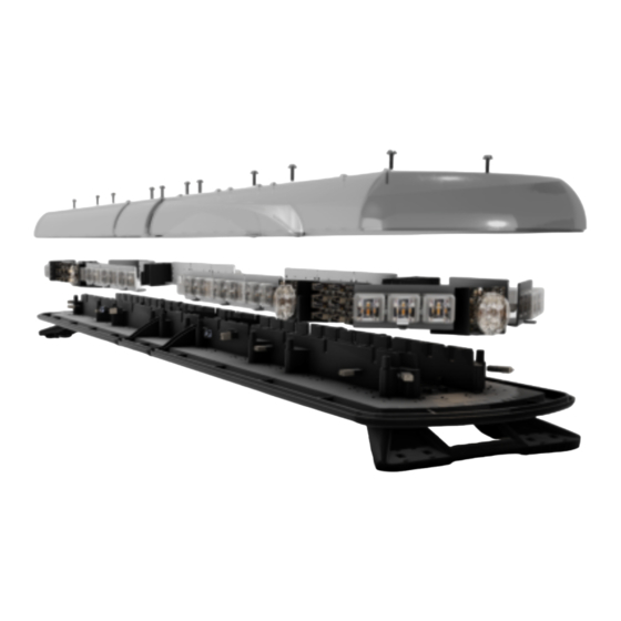
Unpacking and Pre-Installation:
Carefully remove the lightbar and place it on a flat surface. Examine the unit for transit damage and locate all parts. If damage is found or
parts are missing, contact the transit company or ECCO. Do not use damaged or broken parts. Ensure the lightbar voltage is compatible with
the planned installation.
Specifications:
Length.................24", 30", 36", 42", 48",54",60",72"
Height..................2.5"
Width...................11"
Voltage................12-24VDC
Current Draw.......Single Color LED Module = 0.45A Avg. @ 12.8VDC
Dual Color LED Module = 0.90A Avg. @ 12.8VDC
LED STT(pair) = 0.25A Avg.@ 12.8VDC
LED AL,TD,WL (pair) = 1.80A Avg. @ 12.8VDC
Flash Patterns.....48 (See chart)
Installation & Mounting:
Mounting
Before proceeding with installation, plan all wiring and cable routing. Select the mounting location for the lightbar on a flat, smooth surface
and center the unit across the width of the vehicle. The mounting location for the lightbar should be chosen such that the lightbar is level
and visibility to approaching traffic is optimized. Mounting should be such that there is no less than ½" clearance between the roof and the
lightbar at any point.
Installation and Operation Instructions
12+ Series Vantage™ Lightbars
Advertisement
Table of Contents

Related Manuals for Ecco Vantage 12+ Series


Summary of Contents for Ecco Vantage 12+ Series
- Page 1 Carefully remove the lightbar and place it on a flat surface. Examine the unit for transit damage and locate all parts. If damage is found or parts are missing, contact the transit company or ECCO. Do not use damaged or broken parts. Ensure the lightbar voltage is compatible with the planned installation.
- Page 2 Caution: When drilling into any vehicle surface, make sure that the area is free from any electrical wires, fuel lines, vehicle upholstery, vehicle support members, etc. that could be damaged. Safety Director Flash Pattern Chart Sequence Description SAE J595 Left Left Build Right Right Build...
- Page 3 Pattern 1 Wire Connection SAE J845 SAE J595 CA T13 Single Front 125 C1A C1A C1A C1A C1 C1 C1 C1 Single Rear 125 C1A C1A C1A C1A C1 C1 C1 C1 Single Front Alternating Left/Right 125 C1S C1S C1S C1S C1 C1 C1 C1 Single Rear Alternating Left/Right 125 C1S C1S C1S C1S C1...
- Page 4 Single 125 C1A C1A C1A C1A C1 C1 C1 C1 - Double 125 C1A C1A C1A C1A C1 C1 C2 C1 - Quad 125 C1A C1A C1A C1A C1 C1 C2 C1 - 8 Pulse 125 C1A C1A C1A C1A C2 C2 C2 C1 - Single Alternating Left/Right...
- Page 5 Pattern 2 Wire Connection SAE J845 SAE J595 CA T13 Single 125 C1A C1A C1A C1A C1 C1 C1 C1 - Double 125 C1A C1A C1A C1A C1 C1 C2 C1 - Quad 125 C1A C1A C1A C1A C1 C1 C2 C1 - 8 Burst 125 C1A C1A C1A C1A C2 C2 C2 C1 -...
- Page 6 Front Steady On - C1 - Back Steady On - C1 - Single Front 125 C1S C1S C1S C1S C1 C1 C1 C1 - Single Rear 125 C1S C1S C1S C1S C1 C1 C1 C1 - Single Front Alternating Left/Right 125 C1S C1S C1S C1S C1 C1 C1 C1 -...
- Page 7 Ideally, the outermost holes on the feet should be used for installation. The inner holes on the feet match the hole locations for ECCO 15 series lightbar and can be used when one of these lightbars has been previously installed.
- Page 8 Gutter Mounting Important! Mounting brackets are specific to the vehicle model. Please make sure the brackets are suitable for the vehicle before installation. 1. Remove mounting foot. Position bracket onto nubs of the foot. 2. Holding the bracket and foot together, insert the cage nut as shown. It will fit snugly underneath the mounting foot. Do not install it on the outside face.
-
Page 9: Wiring Instructions
Wiring Instructions: Important! This unit is a safety device and it must be connected to its own separate, fused power point to assure its continued operation should any other electrical accessory fail. Do not wire in parallel with any other accessory. Notes: 1. - Page 10 STANDARD CONFIGURATION WITH CONTROLLER 12+ SERIES LIGHTBAR STTs OPTIONAL BROWN (TAIL) BLACK NOTE: GREEN AND YELLOW YELLOW (LEFT TURN) WIRE FUNCTIONS ARE SWAPPED IN LIGHTBARS WITH GREEN (RIGHT TURN) PASSENGER SIDE CABLE EXIT. USE THE RED WIRE IN 3-WIRE IGNITION RED (STOP) SYSTEMS ONLY.
- Page 11 CAN BUS CONFIGURATION WITH ADVANCED CONTROLLER 12+ SERIES LIGHTBAR STTs OPTIONAL BROWN (TAIL) BLACK NOTE: GREEN AND YELLOW YELLOW (LEFT TURN) WIRE FUNCTIONS ARE SWAPPED IN LIGHTBARS WITH GREEN (RIGHT TURN) PASSENGER SIDE CABLE EXIT. USE THE RED WIRE IN 3-WIRE IGNITION RED (STOP) SYSTEMS ONLY.
- Page 12 CAN BUS CONFIGURATION WITH JUNCTION BOX AND ADVANCED CONTROLLER JBOX 12+ SERIES LIGHTBAR WHITE (SYNC) BROWN (AUX (+) OUT) STTs OPTIONAL BROWN (TAIL) BLACK NOTE: GREEN AND YELLOW YELLOW (LEFT TURN) WIRE FUNCTIONS ARE 1-2 A SWAPPED IN LIGHTBARS WITH GREEN (RIGHT TURN) PASSENGER SIDE CABLE EXIT.
-
Page 13: Options And Maintenance
Options and Maintenance: Occasional cleaning of the lenses will ensure optimum light output. Take care when cleaning lenses – although tough, polycarbonate scratches easily. Clean the lens and base with soap and water or a lens polish using a soft cloth. Do not use solvents as they may damage the polycarbonate. -
Page 14: Operation
Stop / Tail / Turn LED Modules (EZ1205) Stop Tail Turn modules operate in conjunction with the vehicle tail, brake and direction indicator lights. Kit includes a pair of modules, control circuit and cable. Basic Control Pad (EZ0006) The EZ0006 optional in-cab controller provides convenient control of the lightbar’s built-in flash patterns and features soft touch buttons and LED function indicator lights. - Page 15 Advanced Control Pad (EZ1202) The EZ1202 optional in-cab advanced control pad provides convenient control of the lightbar’s built-in flash patterns and features soft touch buttons and LED func- tion indicator lights. Operation The 12+ series advanced control pad consists of 11 buttons. “Power”...
-
Page 16: Special Features
“Safety Director On/Off” - Will resume pattern selected. “Safety Director Pattern Select” - Press once to cycle to the next Safety Director flash pattern. There is a 5 second delay between the controller and the lightbar. Press and hold for 3 seconds to return to the prior flash pattern. - Page 17 Basic Control Pad Mounting: To mount the control pad with Velcro, separate the two circular halves, remove the backing and adhere one piece on the ve- hicle dashboard and adhere the other to the back of the control pad. To mount the control pad using the swivel mount, first mount the swivel unit to the dashboard with either the supplied screws (note, the suction cup will not work after drilling screws through the swivel base) or by turning the lever at the base of...
-
Page 18: Replacement Parts/Accessories
Replacement Parts/Accessories:... -
Page 20: Troubleshooting
Troubleshooting: All lightbars are thoroughly tested prior to shipment. However, should you encounter a problem during installation or during the life of the product, follow the guide below for troubleshooting and repair information. If the problem cannot be rectified using the solutions given below, additional information may be obtained from the manufacturer –...
Need help?
Do you have a question about the Vantage 12+ Series and is the answer not in the manual?
Questions and answers