Advertisement
Available languages
Available languages
IMPORTANT! Read all instructions before installing and using. Installer: This manual must be delivered to the end user.
WARNING!
Failure to install or use this product according to manufacturer's recommendations may result in property damage, serious injury, and/
or death to those you are seeking to protect!
Do not install and/or operate this safety product unless you have read and understood the safety information
contained in this manual.
1.
Proper installation combined with operator training in the use, care, and maintenance of emergency warning devices are essential to
ensure the safety of emergency personnel and the public.
2.
Emergency warning devices often require high electrical voltages and/or currents. Exercise caution when working with live electrical
connections.
3.
This product must be properly grounded. Inadequate grounding and/or shorting of electrical connections can cause high current arcing,
which can cause personal injury and/or severe vehicle damage, including fire.
4.
Proper placement and installation is vital to the performance of this warning device. Install this product so that output performance of
the system is maximized and the controls are placed within convenient reach of the operator so that they can operate the system without
losing eye contact with the roadway.
5.
Do not install this product or route any wires in the deployment area of an air bag. Equipment mounted or located in an air bag
deployment area may reduce the effectiveness of the air bag or become a projectile that could cause serious personal injury or death.
Refer to the vehicle owner's manual for the air bag deployment area. It is the responsibility of the user/operator to determine a suitable
mounting location ensuring the safety of all passengers inside the vehicle particularly avoiding areas of potential head impact.
6.
It is the responsibility of the vehicle operator to ensure daily that all features of this product work correctly. In use, the vehicle operator
should ensure the projection of the warning signal is not blocked by vehicle components (i.e., open trunks or compartment doors),
people, vehicles or other obstructions.
7.
The use of this or any other warning device does not ensure all drivers can or will observe or react to an emergency warning signal.
Never take the right-of-way for granted. It is the vehicle operator's responsibility to be sure they can proceed safely before entering an
intersection, drive against traffic, respond at a high rate of speed, or walk on or around traffic lanes.
8.
This equipment is intended for use by authorized personnel only. The user is responsible for understanding and obeying all laws
regarding emergency warning devices. Therefore, the user should check all applicable city, state, and federal laws and regulations. The
manufacturer assumes no liability for any loss resulting from the use of this warning device.
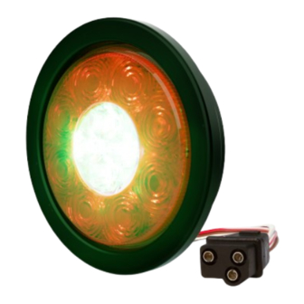
Specifications:
Size: 4" diameter
Weight: 0.6 lb. (0.27 kg)
Input Voltage: 12-24 VDC
Max Power at 12.8 V: 14.1 W
Max Current at 12.8 V: 1.1 A
DOT Type: I, S, T, R, W-1
Installation and Operation Instructions
ED3040 LED Stop-Turn-Tail-Reverse
and Warning Combo Light
Installation & Mounting:
Mounting with supplied rubber grommet:
1. Cut 4.5" diameter hole in desired mounting location.
2. Insert the rubber grommet into the hole until flange is against
mounting surface.
3. Route wires through grommet and press light into the grommet
until light is flush with grommet surface.
Mounting with flange (sold separately):
1. Cut 4.5" diameter hole in desired mounting location.
2. Paying attention to the "TOP" of the flange place it in the hole
and mark the screw hole locations. See Figure 1.
3. Pre-drill holes with 3/16" drill bit (or recommended drill for
selected hardware).
4. Install flange using #12 hardware appropriate for material to be
mounted to.
5. Feed wires through flange and insert light into flange while
aligning key in light to feature in flange. Light will snap into
place. See Figure 2.
Page 1 of 5
Advertisement
Table of Contents

Related Manuals for Ecco ED3000


Summary of Contents for Ecco ED3000
- Page 1 Installation and Operation Instructions ED3040 LED Stop-Turn-Tail-Reverse and Warning Combo Light IMPORTANT! Read all instructions before installing and using. Installer: This manual must be delivered to the end user. WARNING! Failure to install or use this product according to manufacturer’s recommendations may result in property damage, serious injury, and/ or death to those you are seeking to protect! Do not install and/or operate this safety product unless you have read and understood the safety information contained in this manual.
- Page 2 Synchronization: ED3040 series are capable of syncing with other compatible ECCO products by following these steps: 1. Set the desired flash pattern on each unit individually. It is also strongly recommended that the same style of flash pattern be used on all units to produce the most effective warning pattern.
- Page 3 Flash Pattern Chart Tabla de patrones de destello Tableau des effets clignotants SAE J59 CAT13 SAE J595 Red Wire White Wire Red and White Wires Description SYNC. Phase FPM AMBER BLUE WHITE GREEN AMBER 1‐Default Single Flash Color 1 Class 1M Class 2M Class 1M Class 3M Class B Single Flash Color 1 Class 1M Class 2M Class 1M Class 3M Class B Single Flash Color 1 Alternately Color 2...
- Page 4 Quad Color 2 Class 1M Class 2M Class 1M Class 3M Quad Color 1 Alternately Color 2 Quad Color 1 Alternately Color 2 Quad Color 1 Alternately Color 2 Modulation Color 1 Alternately Color 2 2 Double, 2 Quad Color 1 Alternately Color 2 4 Single,2 Triple Color 1 Alternately Color 1 Double 1Triple 1 Quad Color 1...
- Page 5 Electronics Controls Company “ECCO” (Manufacturer) ECCO warrants that on the date of purchase, this product will conform to ECCO’s specifications for this product (which are available from ECCO upon re- quest). This Limited Warranty extends for sixty (60) months from the date of purchase.
-
Page 6: Especificaciones
Instrucciones de instalación y operación Combinación de luces LED de freno,direccional, trasera, reversa yadvertencia ED3040 ¡IMPORTANTE! Lea todas las instrucciones antes de instalar y utilizar. Instalador: Este manual se debe entregar al usuario final. ¡ADVERTENCIA! Si no sigue las instrucciones del fabricante a la hora de instalar o usar el producto, pueden producirse daños materiales, y lesiones graves o incluso mortales a aquellos que pretende proteger! No instale ni opere este producto de seguridad, a menos que haya leído y comprendido la información de seguridad contenida en este manual. - Page 7 NOTA: Se puede utilizar un conector PL3 macho (no incluido), pero no es necesario. Corte el conector PL3 hembra para cablear la unidad. Sincronización: La serie ED3040 se puede sincronizar con otros productos ECCO compatibles a través de los siguientes pasos: 1. Ajuste el patrón de destello deseado en cada unidad de manera individual. También se recomienda encarecidamente que se utilice el mismo estilo de patrón de destello en todas las unidades para producir el patrón de advertencia más efectivo.
- Page 8 833 West Diamond St, Boise, Idaho 83705 Servicio Al Cliente EE.UU. 800-635-5900 Reino Unido +44 (0)113 237 5340 | AUS +61 (0)3 63322444 ECCOESG.com An ECCO SAFETY GROUP™ Brand ECCOSAFETYGROUP.com © 2020 ECCO, Inc. Todos los derechos reservados. 920-0861-00 Rev. C Página 3 de 3...
-
Page 9: Spécifications
Instructions d'installation et d'utilisation Combiné de feu d’arrêt, de virage, de freinage, de recul et de détresse à DEL de la série ED3040 IMPORTANT! Lisez toutes les instructions avant d’installer et d’utiliser le produit. Installateur : ce manuel doit être remis à l’utilisateur final. AVERTISSEMENT! Le non-respect des recommandations du fabricant au cours de l’installation ou de l’utilisation de ce produit peut entraîner des dommages matériels et causer à... - Page 10 Synchronisation: La série ED3040 est capable de se synchroniser avec d’autres produits ECCO compatibles en procédant comme suit: 1. Réglez le schéma de clignotement souhaité sur chaque unité individuellement. Il est aussi fortement recommandé d’utiliser le même style d’effet de clignotement sur toutes les unités pour produire l’avertissement le plus efficace.
- Page 11 833 West Diamond St, Boise, Idaho 83705 Le Service Client États-Unis 800-635-5900 Royaume-Uni +44 (0)113 237 5340 | AUS +61 (0)3 63322444 ECCOESG.com An ECCO SAFETY GROUP™ Brand ECCOSAFETYGROUP.com © 2020 ECCO, Inc. Tous droits réservés. 920-0861-00 Rev. C Page 3 sur 3...
Need help?
Do you have a question about the ED3000 and is the answer not in the manual?
Questions and answers