Advertisement
Available languages
Available languages
Quick Links
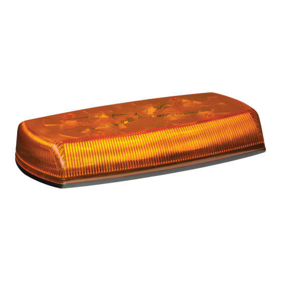
5580 Series - Reflex™ LED Minibars provide a compact
yet powerful warning solution that offers the flexibility of
either permanent, magnet, or vacuum-magnet mounting.
All models feature 12-24 VDC operation and use LED
reflector technology to maximize light output, offering
multiple flash patterns including double, quad quint, rotate
and random. 5587 models have no lens optics, distribut-
ing light directly from the LED reflectors while 5580 &
5585 models feature lenticular lens optics to provide more
diffused light dispersion.
!
WARNING!
Failure to install or use this product according to manufacturers recommendations may result in property damage, serious injury, and/or death to
those you are seeking to protect!
Do not install and/or operate this safety product unless you have read and understand the safety information
contained
1.
Proper installation combined with operator training in the use, care, and maintenance of emergency warning devices are essential to ensure
the safety of you and those you are seeking to protect.
2.
Exercise caution when working with live electrical connections.
3.
This product must be properly grounded. Inadequate grounding and/or shorting of electrical connections can cause high current arcing,
which can cause personal injury and/or severe vehicle damage, including fire.
4.
Proper placement and installation are vital to the performance of this warning device. Install this product so that output performance of the
system is maximized and the controls are placed within convenient reach of the operator so that s/he can operate the system without losing
eye contact with the roadway.
5.
Do not install this product or route any wires in the deployment area of an air bag. Equipment mounted or located in an air bag deployment
area may reduce the effectiveness of the air bag or become a projectile that could cause serious personal injury or death. Refer to the
vehicle owner's manual for the air bag deployment area. It is the responsibility of the user/operator to determine a suitable mounting location
ensuring the safety of all passengers inside the vehicle particularly avoiding areas of potential head impact.
6.
It is the responsibility of the vehicle operator to ensure during use that all features of this product work correctly. In use, the vehicle operator
should ensure the projection of the warning signal is not blocked by vehicle components (i.e., open trunks or compartment doors), people,
vehicles or other obstructions.
7.
The use of this or any other warning device does not ensure all drivers can or will observe or react to a warning signal. Never take the right-
of-way for granted. It is your responsibility to be sure you can proceed safely before entering an intersection, driving against traffic, respond-
ing at a high rate of speed, or walking on or around traffic lanes.
8.
This equipment is intended for use by authorized personnel only. The user is responsible for understanding and obeying all laws regarding
warning signal devices. Therefore, the user should check all applicable city, state, and federal laws and regulations. The manufacturer as-
sumes no liability for any loss resulting from the use of this warning device.
Specifications:
Size:
5580X, 5580XX, 5585X, 5585XX, 5585XXX
5587X, 5587XX, 5587XXX
5580X-MG, 5580XX-MG, 5585X-MG
5585XX-MG, 5585XXX-MG, 5587X-MG,
5587XX-MG, 5587XXX-MG
5580X-VM, 5580XX-VM, 5585X-VM,
5585XX-VM, 5585XXX-VM, 5587X-VM
5587XX-VM, 5587XXX-VM
Available colors: CA,CB,CC,CR,CG,CAC,CAB,CAR,CRA,CAG,CRB
Weight:
Permanent mount
Magnet Mount
Vacuum-Magnet Mount
Input Voltage:
12 to 24 VDC systems
Installation & Mounting:
Important! This unit is a safety device, and it must be
connected to its own separate, fused power point to assure
its continued operation should any other electrical accessory
fail.
Carefully remove the Minibar and place it on a flat surface. Exam-
ine the unit for transit damage, and locate all parts. If damage is
found, or parts are missing, contact the transit company or ECCO.
Do not use damaged or broken parts.
920-0149-00 Rev. K
Installation and Operation Instructions
15" x 9" x 2.5"
15" x 9" x 3.0"
15" x 9" x 31"
approx. 3.4 lbs.
approx. 4.0 lbs.
approx. 5.7 lbs.
5500 Series LED Minibars
Current Draw:
5580: 2.7 Amps Maximum
Maximum power consumption: 35 watts
5585: 5.1 Amps Maximum
Maximum power consumption: 66 watts
5587: 5.1 Amps Maximum
Maximum power consumption: 66 watts
Flash Rate:
See Flash Pattern Chart
Temp. Range:
-30ºC to +50ºC
Vacuum-Magnet Mount:
The Vacuum-Magnet Mount feature includes suction cups on the
bottom of the minibar, with a magnet inside of the suction cup, for a
secure, temporary mount. The minibar should be placed in the center
of the roof where the least amount of curvature occurs. Before install-
ing, make sure the mounting surface is clean and there is no debris
on the bottom of the minibar or on the roof of the vehicle, which could
reduce the holding power of the suction cup and magnet. Place and
remove the minibar without sliding to avoid scratching the paint on
the vehicle. After placement, the minibar should adhere firmly to the
surface. If the unit slides or moves easily, a proper installation has not
been obtained. To release the vacuum, lift the tab to release the air-
lock (see Figure 1). To protect the Vacuum-Magnet Mount assembly,
return minibar to the box when not in use. Do not attempt to attach
the minibar to an ice-covered surface.
Page 1 of 12
Advertisement

Related Manuals for Ecco 5580 Series


Summary of Contents for Ecco 5580 Series
- Page 1 If damage is return minibar to the box when not in use. Do not attempt to attach found, or parts are missing, contact the transit company or ECCO. Do not use damaged or broken parts.
- Page 2 Caution: When drilling into any vehicle surface, make sure the area is free from any electrical wires, fuel lines, vehicle upholstery, etc. that could be damaged WARNING! Maximum recommended vehicle speed for safe operation using the Permanent Mounting: Vacuum Mount model is 65 mph (104 km/h), when fitted to the center of a vehicle roof of steel construction.
- Page 3 A switch may be used to control the on/off function. switch on the cigarette plug. Flash Pattern Syncing: The 5585 permanent mount models sync with other compatible ECCO products via the blue wire: 1. Determine the desired style of flash pattern for each unit and set each unit individually (without the BLUE wires connected together) to avoid confusion.
- Page 4 Manufacturer Limited Warranty and Limitation of Liability: Manufacturer warrants that on the date of purchase, this product will conform to Manufacturer’s specifications for this product (which are available from the Manufacturer upon request). This Limited Warranty extends for thirty-six (36) months from the date of purchase. DAMAGE TO PARTS OR PRODUCTS RESULTING FROM TAMPERING, ACCIDENT, ABUSE, MISUSE, NEGLIGENCE, UNAPPROVED MODIFICATIONS, FIRE OR OTHER HAZARD;...
- Page 5 Examine la unidad para detectar si se produjeron daños durante el aprox. 2,6 kg. (5,7 libras) traslado y ubique todas las piezas. Si se encuentran daños o si faltan piezas, comuníquese con la empresa de transporte o con ECCO. No Tensión de entrada: utilice piezas dañadas o rotas.
- Page 6 Montaje de vacío magnético: La característica de montaje de vacío magnético incluye ventosas de succión en la ¡Precaución! Al perforar cualquier superficie del parte inferior de la Minibar, con un imán dentro de la ventosa para lograr un montaje vehículo, asegúrese de que no haya cables eléctricos, temporario y seguro.
- Page 7 Sincronización del patrón de intermitencia: Los modelos de montaje permanente 5585 se sincronizan con otros productos ECCO compatibles a través del cable azul: Determine el estilo deseado de patrón de intermitencia de cada unidad y configúrelas en forma individual (sin conectar los cables AZULES entre si) para evitar confusiones.
- Page 8 Limitación de responsabilidad y garantía limitada del fabricante: El fabricante garantiza que al momento de la compra, este producto cumple con las especificaciones del fabricante para el mismo (disponibles a pedido). El fabricante garantiza además que el presente producto está libre de defectos en sus materiales y en su fabricación.
- Page 9 Montage à vide magnétique env. 5,7 lb. transport ou ECCO. N’utilisez pas de pièces cassées ou abîmées. Tension d’entrée : Systèmes de 12 à 24 V CC 920-0149-00 Rév. K...
- Page 10 Montage à vide magnétique : L’option de montage à vide magnétique inclut des ventouses sur le dessous de la mini-barre, avec un aimant dans la ventouse pour un montage temporaire sécurisé. La mini-barre doit être placée au centre du toit, à l’endroit où la courbure est la Attention! Lorsque vous percez un trou dans une surface moins importante.
- Page 11 Mise en synchronisme du mode de clignotement : Les modèles à montage définitif 5585 sont synchronisés avec d’autres produits ECCO compatibles par le fil bleu : 1. Déterminez le mode de clignotement souhaité pour chaque unité et réglez chaque unité individuellement (sans raccorder les fils BLEUS les uns aux autres) pour éviter toute confusion.
- Page 12 Garantie limitée et limitation de responsabilité du fabricant : Le fabricant garantit qu’à la date d’achat ce produit sera conforme aux caractéristiques techniques définies par ses soins (disponibles sur demande) et qu’il est exempt de vices de fabrication et de main-d’œuvre. La présente garantie limitée est valable trente-six (36) mois à compter de la date d’achat.
Need help?
Do you have a question about the 5580 Series and is the answer not in the manual?
Questions and answers