Advertisement
Quick Links
IMPORTANT! Read all instructions before installing and using. Installer: This manual must be delivered to the end user.
WARNING!
Failure to install or use this product according to manufacturer's recommendations may result in property damage, serious injury, and/or death to
those you are seeking to protect!
Do not install and/or operate this safety product unless you have read and understood the safety information
contained in this manual.
1.
Proper installation combined with operator training in the use, care, and maintenance of emergency warning devices are essential to ensure the
safety of emergency personnel and the public.
2.
Emergency warning devices often require high electrical voltages and/or currents. Exercise caution when working with live electrical connections.
3.
This product must be properly grounded. Inadequate grounding and/or shorting of electrical connections can cause high current arcing, which can
cause personal injury and/or severe vehicle damage, including fire.
4.
Proper placement and installation is vital to the performance of this warning device. Install this product so that output performance of the system is
maximized and the controls are placed within convenient reach of the operator so that they can operate the system without losing eye contact with
the roadway.
5.
Do not install this product or route any wires in the deployment area of an air bag. Equipment mounted or located in an air bag deployment area
may reduce the effectiveness of the air bag or become a projectile that could cause serious personal injury or death. Refer to the vehicle owner's
manual for the air bag deployment area. It is the responsibility of the user/operator to determine a suitable mounting location ensuring the safety of
all passengers inside the vehicle particularly avoiding areas of potential head impact.
6.
It is the responsibility of the vehicle operator to ensure daily that all features of this product work correctly. In use, the vehicle operator should
ensure the projection of the warning signal is not blocked by vehicle components (i.e., open trunks or compartment doors), people, vehicles or other
obstructions.
7.
The use of this or any other warning device does not ensure all drivers can or will observe or react to an emergency warning signal. Never take the
right-of-way for granted. It is the vehicle operator's responsibility to be sure they can proceed safely before entering an intersection, drive against
traffic, respond at a high rate of speed, or walk on or around traffic lanes.
8.
This equipment is intended for use by authorized personnel only. The user is responsible for understanding and obeying all laws regarding
emergency warning devices. Therefore, the user should check all applicable city, state, and federal laws and regulations. The manufacturer assumes
no liability for any loss resulting from the use of this warning device.
CONTENTS:
1
Light Head
1
Gasket
2
M4x25 Sheet metal screws
Wire: ED3701
RED: Positive(need to add 2A Fuse)
BLACK: Negative
BLUE: Pattern Switch
YELLOW: Synchronized Function
(Up to 8 units can be Synchronized)
Wire: ED3702
RED: Positive, Colors 1 & 3 (need to add 5A Fuse)
WHITE: Positive, Colors 2 & 4 (need to add 5A Fuse)
BLACK: Negative
BLUE: Pattern Select to negative
YELLOW: Synchronized Function
(Up to 8 units can be Synchronized)
Operation Environment:
Ambient Temperature: -30 to 50°C
Mounting:
1. The ED3700 series directionals should be mounted to a flat surface or one with the least amount of curvature. The mounting location should allow the maximum
visibility ofthe warning device to other road users, while allowing for sufficient wire access.
2. Mark drill hole locations on the mounting surface using the directional as a template.
3. Drill mounting holes using a #31[0.120"] drill bit.
4. Drill a 25/64"[10mm] hole for the wires protruding from the rear of the unit at the location. Remove any sharp edges from this hole.
5. Mount the directional along with the mounting gasket, routing the wires through the 10mm hole and use additional grommets or cable protection as necessary to
protect the wiring from any sharp edges. Secure the directional to the surface using the #6 self-tapping screws.
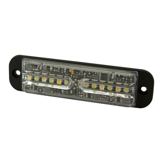
Installation and Operation Instructions
Directional LED
SPECIFICATIONS:
Input Voltage
Work Current
Important! This unit is a safety device and it must be connected to its own separate, fused
power point to assure its continued operation should any other electrical accessory fail.
Caution: When drilling into any vehicle surface, make sure the area is free from any electrical
wires, fuel lines, vehicle upholstery, etc. that could be damaged
Phase Opertion:
Phase 1 (Ph1) flashes simultaneously with Ph1
Phase 2 (Ph2) flashes simultaneously with Ph2
Ph1 alternates with Ph2
(Up to 8 units can be Synchronized)
Apply BLUE TO BLACK wire:
-Less than 1 sec. for next pattern
-Between 1-3 sec for previous pattern
-Between 3-5 sec. for factory default pattern
-More than 5 sec. for pattern 12 (ED3702) and pattern 13
(ED3701)
12-24VDC
ED3701 = 1.0A@12VDC
ED3702 = 1.2A@12VDC
Page 1 of 5
Advertisement

Related Manuals for Ecco ED3702


Summary of Contents for Ecco ED3702
- Page 1 -Less than 1 sec. for next pattern -Between 1-3 sec for previous pattern Operation Environment: -Between 3-5 sec. for factory default pattern -More than 5 sec. for pattern 12 (ED3702) and pattern 13 Ambient Temperature: -30 to 50°C (ED3701) Mounting: 1.
- Page 2 ED3701 Series Flash Pattern Chart Diagrama de patrones de intermitencia de la Serie ED3701 Tableau des modes de clignotement de la série ED3701 Page 2 of 5...
- Page 3 SINGLE COLOR Flash Pattern Chart/DE UN SOLO COLOR Tabla de patrones de destello/COULEUR UNIQUE Tableau des effets clignotants SAE J595 CA T13 ECE R65 Pattern PATTERNS MODE Mark SYNC. AMBER BLUE WHITE AMBER BLUE AMBER BLUE Single Flash 75FPM sim. Phase1 Class 1 Class 1 Class 1...
- Page 4 DUAL COLOR Flash Pattern Chart/COLOR DOBLE Tabla de patrones de destello/BICOLORE Tableau des effets clignotants LED Color 1 & Color 3 SAE J595 CA T13 ECE R65 LED Color 1 & Color LED Color 2 & Color PATTERNS Pattern LED Color 2 & Color 4 Mark SYNC.
Need help?
Do you have a question about the ED3702 and is the answer not in the manual?
Questions and answers