
Subscribe to Our Youtube Channel
Related Manuals for Cincoze DV-1100


Summary of Contents for Cincoze DV-1100
- Page 1 DV-1100 User Manual Rugged Embedded Computer 13/12th Gen. Intel® Core™ Series High Performance and Basic Function Rugged Embedded Computer Version: V1.00...
-
Page 2: Table Of Contents
3.7 Installing M.2 Key M Module ....................46 3.8 Installing M.2 Key B Module ....................47 3.8.1 M.2 Key B type 3052 ......................47 3.8.2 M.2 Key B type 3042 ......................48 3.8.3 M.2 Key B type 2242 ......................49 DV-1100 | User Manual... - Page 3 4.3.14 NVMe Configuration ......................81 4.4 Chipset Setup ........................82 4.4.1 System Agent (SA) Configuration ..................82 4.4.2 PCH-IO Configuration ......................84 4.5 Security Setup ........................87 4.6 Boot Setup ..........................88 4.7 Save & Exit ..........................89 DV-1100 | User Manual...
- Page 4 Chapter 5 Product Application ......................90 5.1 Where to download drivers? ....................91 5.2 Where to find the technical documents? ................91 DV-1100 | User Manual...
-
Page 5: Preface
2024/05/31 Copyright Notice © 2024 by Cincoze Co., Ltd. All rights are reserved. No parts of this manual may be copied, modified, or reproduced in any form or by any means for commercial use without the prior written permission of Cincoze Co., Ltd. All information and specification provided in this manual are for reference only and remain subject to change without prior notice. -
Page 6: Product Warranty Statement
(such as a fuse, battery, etc.), are not warranted. Before sending your product in, you will need to fill in Cincoze RMA Request Form and obtain an RMA number from us. Our staff is available at any time to provide you with the most friendly and immediate service. -
Page 7: Technical Support And Assistance
Limitation of Liability Cincoze’ liability arising out of the manufacture, sale, or supplying of the product and its use, whether based on warranty, contract, negligence, product liability, or otherwise, shall not exceed the original selling price of the product. The remedies provided herein are the customer’s sole and exclusive remedies. -
Page 8: Conventions Used In This Manual
12. Never pour any liquid into an opening. This may cause fire or electrical shock. 13. Never open the equipment. For safety reasons, the equipment should be opened only by qualified service personnel. DV-1100 | User Manual... -
Page 9: Package Contents
9-48 VDC, minimum 8.5-1.5A, with minimum rated maximum ambient temperature 70°C, and has to be evaluated according to IEC/EN 60950-1 and/or IEC/EN 62368-1. If need further assistance, please contact Cincoze for further information. 17. Ensure to connect the power cord of power adapter to a socket-outlet with earthing connection. -
Page 10: Ordering Information
Ordering Information Model No. Product Description 13/12th Gen. Intel® Core™ Series High Performance and Basic Function DV-1100-R10 Rugged Embedded Computer DV-1100 | User Manual... -
Page 11: Chapter 1 Product Introductions
Chapter 1 Product Introductions DV-1100 | User Manual... -
Page 12: Overview
Intel® processors. Its balance between high-performance computing needs and cost-e- ffectiveness enables enterprises to quickly analyze and process edge data for better decision-making and improved production efficiency and accuracy. The DV-1100 is ideal for smart manufacturing, machine vision, railway computing, and space-constrained applications where stability and reliability are paramount. - Page 13 USB 3.2 Gen2x1. Storage support includes 2.5” HDD/SSD and high-speed NVMe SSD. Excellent Extension Design The DV-1100 has built-in M.2 Key B, M.2 Key E, and M.2 Key M slots for flexible wireless (5G, Wi-Fi, GNSS) and storage selection according to application requirements. Various Industry...
-
Page 14: Hardware Specification
• Integrated Intel® UHD Graphics 710: Pentium®/Celeron® • Supports Triple Independent Display Maximum Display Output • 1x DisplayPort Connector: 3840 x 2160 @60Hz • 1x VGA Connector: 1920 x 1200 @60Hz • 1x CMI Interface for Optional CMI-DP/CMI-HDMI Module Expansion CMI Display DV-1100 | User Manual... - Page 15 • 1x AT/ATX Mode Switch Power Mode Switch • 9-48VDC, 3-pin Terminal Block Power Input • 1x Remote Power On/Off, 2-pin Terminal Block Remote Power On/Off • 1x Remote Power LED, 2-pin Terminal Block Remote Power LED DV-1100 | User Manual...
- Page 16 • EN/BS EN 61000-3-3 Voltage fluctuations & flicker • FCC 47 CFR Part 15B, ICES-003 Conducted & Radiated: Class A • EN/IEC 61000-4-2 ESD: Contact: 6 kV; Air: 8 kV • EN/IEC 61000-4-3 RS: 80 MHz to 1000 MHz: 20 V/m DV-1100 | User Manual...
- Page 17 • EN/IEC 61000-4-11 Voltage Dips & Voltage Interruptions: 1 cycles at 60 Hz * Product Specifications and features are for reference only and are subject to change without prior notice. For more information, please refer to the latest product datasheet from Cincoze's website. DV-1100 | User Manual...
-
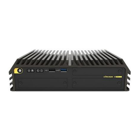
Page 18: External Layout
Universal I/O Bracket IGN Setting Switch GPIO LED 1.3.2 Rear Remote Power On/Off External FAN Power USB3.2 Gen1x1 USB2.0 Antenna Antenna Antenna Antenna COM1 Mic-in Line-out LAN2 LAN1 DC Input Antenna COM2 Remote Power LED Chassis GND DV-1100 | User Manual... -
Page 19: Dimensions
1.4 Dimensions Unit: mm DV-1100 | User Manual... -
Page 20: Chapter 2 Switches & Connectors
Chapter 2 Switches & Connectors DV-1100 | User Manual... -
Page 21: Location Of Switches And Connectors
2.1 Location of Switches and Connectors 2.1.1 Top View USB2_1 USB3_1 SIM1 PWR_SW1 POWER_LED1 HDD_LED3 TEMP_LED3 GPIO_LED1 2.1.2 Bottom View FAN1 COM_1_1 CN10 CN14 AUDIO1 CN15 DC_IN1 VGA1 CN13 SATA1 IGN_PH1 CN12 CN11 DP_B1 BTB_FH2 BTB_FH1 DEBUG1 RESET1 24V_12V_1 CLR_CMOS1 AT_ATX1 DV-1100 | User Manual... -
Page 22: Switches And Connectors Definition
Super CAP Power Control Switch COM1 and COM2 Power Select Switch IGN Module Timing Setting Switch TEMP_LED3 TEMP LED USB2_1 USB2.0 TYPE A Connector USB3_1 USB3.2 GEN2x1 TYPE A Connector VGA1 VGA Connector 24V_12V_1 IGN Module Voltage Mode Setting Switch DV-1100 | User Manual... -
Page 23: Switches Definition
(Après avoir effectué Clear CMOS, le système prendra plusieurs minutes pour démarrer. Cela est normal. Pendant ce processus, le système effectuera trois fois le POST, et la LED d'alimentation du système alternera entre les lumières verte et bleue.) DV-1100 | User Manual... - Page 24 PWR_SW1: System Power Button Switch Definition Push Power up the System RESET1: System Reset Button Switch Definition Push Reset System SW1: Super CAP Control Switch Location Function DIP1 DIP2 Super CAP Enabled ON (Default) ON (Default) Super CAP Disabled DV-1100 | User Manual...
- Page 25 Default setting of Pin1 to Pin4 is OFF / OFF / OFF / OFF. 24V_12V_1:IGN Module Voltage Mode Setting Switch 12V / 24V Car Battery Switch. This switch functions only when applying CFM-IGN04 module. Switch Definition Left 12V Car Battery Input Right 24V Car Battery Input (Default) DV-1100 | User Manual...
-
Page 26: Definition Of Connectors
PCM_IN PCM_OUT WGR_D0N WGR_D0P UART_WAKE# WGR_CLKN BRI_RSP WGR_CLKP RGI_DT RGI_RSP PETp0 BRI_DT PETn0 CLINK_REST CLINK_DATA PERp0 CLINK_CLK PERn0 COEX3 COEX2 REFCLKP0 COEX1 REFCLKN0 SUSCLK PERST0# CLKREQ0# W_DISABLE2# PEWAKE0# W_DISABLE1# I2C_DATA WTD1N/PETP1 I2C_CLK WTD1N/PETN1 WTD0N/PERP1 WTD0P/PERN1 PEWAKE1# DV-1100 | User Manual... - Page 27 USIM _DATA PETn1 /USB3_TX- USIM _PWR PETp1 /USB3_TX+ DEVSLP USIM _DET2 PERn0 /SATA_B+ USIM _DATA2 PERp0 / SATA_B- USIM_CLK2 USIM_RESET2 PETn0 /SATA_A- USIM _PWR2 PETp0 / SATA_A+ PERST# CLKREQ# REFCLKN PEWAKE# REFCLKP COEX3 COEX2 COEX1 USIM _DET DV-1100 | User Manual...
- Page 28 CFG3 +3.3V +3.3V FULL_CARD_POWER_OFF_N USB2_D+ W_DISABLE1_N USB2_D- LED1_N GPIO_5 CFG0 GPIO_6 GPIO_7 GPIO_10 GPIO_8 PERn1 PERp1 PETn1 PETp1 DEVSLP PERn0 /SATA_B+ PERp0 / SATA_B- PETn0 /SATA_A- PETp0 / SATA_A+ PERST# CLKREQ# REFCLKN PEWAKE# REFCLKP COEX3 COEX2 DV-1100 | User Manual...
- Page 29 PERn3 PERp3 LED1# PETn3 +3.3V PETp3 +3.3V +3.3V PERn2 +3.3V PERp2 PETn2 PETp2 PERn1 PERp1 PETn1 PETp1 DEVSLP SMB_CLK PERn0 /SATA_B+ SMB_DATA PERp0 / SATA_B- ALERT# PETn0 /SATA_A- PETp0 / SATA_A+ PERST# CLKREQ# REFCLKN PEWAKE# REFCLKP DV-1100 | User Manual...
- Page 30 (Ne mettez pas sous tension ce connecteur! Ce port est utilisé pour connecter un SWITCH!) FAN1: CPU Smart Fan Connector Connector Type: Terminal Block 1X4 4-pin, 3.5mm pitch Definition +12V SENSE 4 3 2 1 Control DV-1100 | User Manual...
- Page 31 Please disconnect the power source before mounting the DC power cables or connecting the DC power connector to system. (Veuillez débrancher la source d'alimentation avant de monter les câbles d'alimentation CC ou de connecter le connecteur d'alimentation CC au système.) DV-1100 | User Manual...
-
Page 32: Optional Module: Definition Of Switches And Connectors
BTB_FH2, the corresponding COM numbers are COM5 and COM6. When two CMI-COM06 modules are installed at both BTB_FH1 and BTB_FH2, the COM numbers range from COM3 to COM6 shown in the following DV-1100 Front Bezel Diagram. COM1 and COM2 (on the module) : COM3 and COM4 Connector (Support RS232/RS422/RS485) - Page 33 SW1 (on the module) : COM3/COM5 Power Select Switch Location Function DIP1 DIP2 ON (Default) ON (Default) COM3/5 SW1 (on the module) : COM4/COM6 Power Select Switch Location Function DIP3 DIP4 ON (Default) ON (Default) COM4/6 DV-1100 | User Manual...
-
Page 34: Cmi-Dio06 Module
Connector Type: Terminal Block 1X10 10-pin, 3.5mm pitch Definition Definition XCOM+ (DC INPUT) XCOM- (GND) DIO2 (on the module) : Digital OUT Connector Connector Type: Terminal Block 1X10 10-pin, 3.5mm pitch Definition Definition XCOM+ (DC INPUT) XCOM- (GND) DV-1100 | User Manual... -
Page 35: Chapter 3 System Setup
Chapter 3 System Setup DV-1100 | User Manual... -
Page 36: Removing Top Cover
Step 1: Loosen the 6 screws on the bottom panel of the system. Step 2. Remove the bottom panel and then the system body from the chassis. Step 3. Loosen the indicated 2 screws (M3x4). DV-1100 | User Manual... - Page 37 Step 4. Loosen the six red-indicated screws (M3x6) and the orange-indicated screw (M3x8). Step 5. Remove the system body from the top cover. Step 6. Place the system body aside gently. DV-1100 | User Manual...
-
Page 38: Installing Antenna
Install antennas on positions 1, 2, and 3 (from the PCB top side) before installing the CPU to prevent thermal paste from spreading. Antennas in positions 4 and 5 can be installed before or after CPU and the top cover installation. Step 1. Remove the antenna plug on the rear panel. DV-1100 | User Manual... - Page 39 Step 2. Penetrate the antenna jack through the hole. Step 3. Put on the washer and fasten the nut of antenna jack. Step 4. Assemble the antenna and antenna jack together. DV-1100 | User Manual...
-
Page 40: Installing Cpu
CPU to the new CPU, which may cause performance issues or startup failures. Therefore, Cincoze performs a Clear CMOS procedure before shipping. When customers power on the system for the first time, it will take several minutes to start. - Page 41 Step 1. Locate the CPU socket. Step 2. Hold both sides of the cover of the CPU socket and remove it. Step 3. Insert the CPU gently by aligning the notches of the socket. DV-1100 | User Manual...
- Page 42 Step 5. Make sure that the CPU surface is clean, and apply the thermal paste (attached in the CPU Installation Kit) onto the CPU’s surface as shown below. For more detailed information about the thermal paste application, please find the Intel official website. DV-1100 | User Manual...
-
Page 43: Installing So-Dimm
Step 2. Align the SO-DIMM notch with the socket notch. Insert it at a 45-degree angle until the edge connector is securely connected to the SO-DIMM socket. 45° Step 3. Press down the module until the retaining clips snap back in place. DV-1100 | User Manual... -
Page 44: Installing Top Cover
Step 1. Hold the system body and reattach it to the top cover. Step 2. Fasten the six red-indicated screws (M3x6) and the orange-indicated screw (M3x8, removed from Chapter 3.1). These two screws are used to secure the CPU bracket. DV-1100 | User Manual... -
Page 45: Installing 2.5" Sata Hdd/Ssd
4 provided screws (M3x4, attached in the Screw Pack) to securely attach them together. Step 3. Insert the HDD bracket and push it until the HDD connector fully engages with the SATA slot. Step 4. Fix the HDD bracket by fastening the two screws (M3x4, removed from Chapter 3.1). DV-1100 | User Manual... -
Page 46: Installing M.2 Key M Module
Step 2. Tilt the M.2 Key M module at a 45-degree angle and insert it to the socket until the golden finger connector of the card seated firmly. 45° Step 3. Press the module down and secure it with the screw (M3X5, attached in the Screw Pack). DV-1100 | User Manual... -
Page 47: Installing M.2 Key B Module
Step 2. Insert the M.2 Key B type 3052 module at a 45-degree angle and insert it to the slot until the gold-pated connector of module contacted firmly with the slot. Step 3. Press down the module and fasten the screw to secure the module. (M3X5, attached in the Screw Pack). DV-1100 | User Manual... -
Page 48: Key B Type 3042
Secure the bracket in place and fasten the screw (M3x4, attached in the Screw Pack). Step 3. Insert the M.2 Key B module at a 45-degree angle and insert it to the slot until the gold-pated connector of module contacted firmly with the slot. 45° DV-1100 | User Manual... -
Page 49: Key B Type 2242
Step 1. Locate the M.2 Key B type 2242 connector (CN12) on the system motherboard. Step 2. Insert the M.2 Key B type 2242 module at a 45-degree angle and insert it to the slot until the gold-pated connector of module contacted firmly with the slot. 45° DV-1100 | User Manual... -
Page 50: Installing M.2 Key E Module
Step 1. Locate the M.2 Key E connector (CN8) on the system motherboard. Step 2. Tilt the M.2 Key E module at a 45-degree angle and insert it to the socket until the golden finger connector of the card seated firmly. 45° DV-1100 | User Manual... -
Page 51: Installing Cmi Module
Step 3. Press the module down and secure it with the screw (M3X5, attached in the Screw Pack). 3.10 Installing CMI Module 3.10.1 CMI-DP01-R10/UB1606-R10 Module Step 1. Unscrew the 2 screws to remove bracket from front panel. Step 2. Locate the DP_B1 connector. DV-1100 | User Manual... - Page 52 Step 4. Insert the module vertically to the connector, and then fasten the 2 screws to fix it. Step 5. Attach on the CMI-DP01 bracket, and fasten the screws as indicated. Please ensure the Graphics Configuration in the BIOS is set appropriately for successful display from this module. DV-1100 | User Manual...
-
Page 53: Cmi-Hd03-R10/Ub1608-R10 Module
Step 3. Fasten the two copper pillar screws as indicated. When fixing the copper pillars (attached in the CMI module pack), please be careful not to lock them too tightly so as not to damage the boss. It is recommended to use a 4kgf torque wrench to tighten the copper pillars. DV-1100 | User Manual... -
Page 54: Cmi-Com06-R10/Ub1603-R10
3.10.3 CMI-COM06-R10/UB1603-R10 For pin definitions related to this module, please refer to Chapter 2.5.1. Step 1. Loosen the 2 screws on the bracket 1 or 2 at the front bezel and then remove the cover plate. DV-1100 | User Manual... - Page 55 It is recommended to use a 4kgf torque wrench to tighten the copper pillars. Step 4. Insert the module vertically to the connector, and then fasten the 2 screws to fix it. Step 5. Attach on the CMI-COM06 bracket, and fasten the screws as indicated. DV-1100 | User Manual...
-
Page 56: Cmi-Dio06-R10/Ub1618-R20
Step 1. Loosen the 2 screws on the bracket 1 or 2 at the front bezel and then remove the cover plate. Step 2. Locate the BTB_FH1 or BTB_FH2 connector. BTB_FH1 BTB_FH2 Step 3. Attach on the CMI-DIO06 bracket. Fasten the 2 screws to fix it. DV-1100 | User Manual... -
Page 57: Installing Cfm Module
3.11 Installing CFM Module For pin definitions related to this module, please refer to Chapter 2.3 (SW3 and 24V_12V_1). 3.11.1 CFM-IGN04-R10 Step 1. Locate the IGN_PH1 connector. Step 2. Insert the module vertically to the connector DV-1100 | User Manual... -
Page 58: Installing Bottom Cover
Step 1. Place the bottom cover (removed from Chapter 3.1) back to system and fasten it with the 6 screws. 3.13 Removing Maintenance Area Panel Step 1. Loosen the 2 screws on the Maintenance Area Panel and remove it. DV-1100 | User Manual... -
Page 59: Installing Sim Card
The top side is SIM1 slot, and the bottom side is SIM2 slot. Top Side: SIM1 Bottom Side: SIM2 Step 4. Install SIM card(s) into the SIM card adapter. In this installation example, we install a SIM card into the SIM1 Slot. DV-1100 | User Manual... -
Page 60: Replacing Cmos Battery
SIM cards are installed, the network connection will prioritize the card at SIM1. 3.15 Replacing CMOS Battery This chapter introduces the process of replacing the CMOS battery when it has depleted. Step 1. Locate the position of removable CMOS Battery. Step 2. Loosen the screw as indicated. DV-1100 | User Manual... - Page 61 Step 4. Loosen the screw as indicated. Step 5. Pull down the indicated portion and replace the CMOS battery with a new one. (please note the battery’s positive/negative pole orientation when you execute this step). Battery’s negative pole side DV-1100 | User Manual...
- Page 62 Step 6. Fasten the screw back. Step 7. Insert the CMOS battery bracket. Step 8. Fasten the screw back. DV-1100 | User Manual...
-
Page 63: Installing Maintenance Area Panel
This system offers wall mount brackets for customers to install system on the wall in a convenient and economical way. Step 1. The mounting holes are at the bottom side of system. Use provided 8 screws (M3x5L) to fasten the bracket on each side. DV-1100 | User Manual... -
Page 64: Installing Vesa Mount
3.18 Installing VESA Mount The following picture indicates VESA mounting holes on the DV-1100 series, which is compliant with VESA mounting standard. The blue holes correspond to the 75x75mm VESA mounting standard, and the red holes correspond to the 100x100mm VESA mounting standard. -
Page 65: Installing Din-Rail Mount
Step 2. Then, the VESA mount installation is complete. 3.19 Installing DIN-Rail Mount The DV-1100 series offers an optional accessory for DIN-Rail mounting, DIN-RAIL Mount Kit (Model No. DINRAIL-R10) as shown below. If you have acquired this accessory, please refer to the installation instructions hereafter. -
Page 66: Installing External Fan
Step 2. Then user can clip the system into DIN rail through the DIN-RAIL Mount Kit. 3.20 Installing External FAN The DV-1100 series offers an optional accessory of the External FAN (Model No. FAN-EX104) as shown in step 1. If you have acquired this accessory, please refer to the installation instructions hereafter. - Page 67 (the both screws will be in the groove at the same time). Step 4. Tighten the two screws. Step 5. Connect the FAN cable to external fan power connector firmly on the rear panel of the system. DV-1100 | User Manual...
-
Page 68: Chapter 4 Bios Setup
Chapter 4 BIOS Setup DV-1100 | User Manual... -
Page 69: Bios Introduction
( ↑↓ ) to highlight the field and press <Enter> to call up the sub-menu. Then you can use the control keys to enter values and move from field to field within a sub-menu. If you want to return to the main menu, just press the <Esc >. DV-1100 | User Manual... -
Page 70: Main Setup
Set the time. Please use <Tab> to switch between time elements. 4.3 Advanced Setup This section allows you to configure and improve your system and allows you to set up some system features according to your preference. DV-1100 | User Manual... -
Page 71: Cpu Configuration
4.3.1 CPU Configuration ◼ Efficient-core Information This page displays the E-core Information. ◼ Performance-core Information This page displays the P-core Information. DV-1100 | User Manual... -
Page 72: Power & Performance
◼ Active Efficient-cores Allows you to choose the number of active efficient cores. Configuration options: [All] [7] [6] [5] [4] [3] [2] [1] [0]. ◼ Hyper-threading Enables or disables for Hyper-Threading Technology. 4.3.2 Power & Performance DV-1100 | User Manual... -
Page 73: Sata Configuration
Configuration options: [AHCI] ◼ SATA 1 Port [Enabled] Enables or disables SATA 1. ◼ CN13 Port [Enabled] Enables or disables CN13. ◼ CN11 Port [Enabled] Enables or disables CN11. ◼ CN12 Port [Enabled] Enables or disables CN12. DV-1100 | User Manual... -
Page 74: Pch-Fw Configuration
4.3.4 PCH-FW Configuration ◼ Firmware Update Configuration Configure Management Engine Parameters ◼ Me FW Image Re-Flash [Disabled] Enables or disables ME firmware Image Re-Flash function. DV-1100 | User Manual... -
Page 75: Trusted Computing Settings
Enables or disables Storage Hierarchy function. ◼ Endorsement Hierarchy [Enabled] Enables or disables Endorsement Hierarchy function. ◼ Physical Presence Spec Version [1.3] Allows you to select which mode Physical Presence Spec Version will operate. Configuration options: [1.2], [1.3] DV-1100 | User Manual... -
Page 76: Acpi Settings
[Suspend Disabled]: Disables entering suspend state. [S3 (suspend to RAM)]: Enables suspend to RAM state. 4.3.7 F81966 Super IO Configuration Set Parameters of Serial Ports. User can Enable/Disable the serial port and select an optimal setting for the Super IO Device. DV-1100 | User Manual... - Page 77 Enables or disables watch dog function. ◼ Watch Dog Mode [Sec] Allows to set watchdog timer unit <Sec> or <Min>. ◼ Watch Dog Timer [0] Allows you to set watchdog timer’s value in the range of 0 to 255. DV-1100 | User Manual...
-
Page 78: Hardware Monitor
External Smart Fan Configuration Configure External Smart Fan Parameters. ◼ Smart Fan Mode [Auto] Allows you to select Smart Fan Mode. Configuration options: [Auto] [Manual] ◼ Fan Speed Mode [RPM] Allows you to select Fan Speed Mode. DV-1100 | User Manual... -
Page 79: S5 Rtc Wake Settings
[Disabled]: Disables wake system from S5. [Fixed Time]: Sets a fixed time (HH:MM:SS) to wake system from S5. [Dynamic Time]: Sets an increase minute(s) from current time to wake system from S5. 4.3.10 Serial Port Console Redirection DV-1100 | User Manual... -
Page 80: Usb Configuration
Enables or disables XHCI (USB3.0) hand-off function. Use this feature as a workaround for operating systems without XHCI hand-off support. ◼ USB Mass Storage Driver Support [Enabled] Enables or disables USB mass storage driver support. 4.3.12 Network Stack Configuration DV-1100 | User Manual... -
Page 81: Csm Configuration
4.3.14 NVMe Configuration The screen allows users to select options for the NVMe configuration, and change the value of the selected option. If there is NVMe Device detected, the options will show as the NVMe Device is found. DV-1100 | User Manual... -
Page 82: Chipset Setup
4.4 Chipset Setup This section allows you to configure chipset related settings according to user’s preference. 4.4.1 System Agent (SA) Configuration ◼ Memory Configuration This item displays detailed memory configuration in the system. DV-1100 | User Manual... - Page 83 This option enables users to choose the type of CMI Module. The default setting is DP. If the CMI-HDMI module is utilized, kindly ensure to configure this function as [HDMI] to ensure successful display from the CMI-HDMI module. Configuration options: [DP] [HDMI] DV-1100 | User Manual...
-
Page 84: Pch-Io Configuration
◼ PCIe Speed [Auto] Allows you to select PCI Express interface speed. Configuration options: [Auto] [Gen1] [Gen2] [Gen3] [Gen4]. ◼ VT-d [Enabled] Enables or disables Intel® Virtualization Technology for Directed I/O (VT-d) capability. 4.4.2 PCH-IO Configuration DV-1100 | User Manual... - Page 85 ◼ PCI Express Root Port (CN12) ◼ PCI Express Root Port [Enabled] Enables or disables PCI Express Root Port. ◼ PCIe Speed [Auto] Allows you to select PCI Express interface speed. Configuration options: [Auto] [Gen1] [Gen2] [Gen3]. DV-1100 | User Manual...
- Page 86 ◼ Audio Amplifier [Enabled] Enables or disables Audio Amplifier Function. ◼ Power Failure [Keep last state] Allows you to specify which power state system will enter when power is resumed after a power failure (G3 state). DV-1100 | User Manual...
-
Page 87: Security Setup
This section allows users to configure BIOS security settings. ◼ Administrator Password Administrator Password controls access to the BIOS Setup utility. ◼ User Password User Password controls access to the system at boot and to the BIOS Setup utility. ◼ Security Boot DV-1100 | User Manual... -
Page 88: Boot Setup
Allows you to enable or disable Quiet Boot function. ◼ Fast Boot [Disabled] Allows you to enable or disable Fast Boot function. If enabled, system boots with initialization of a minimal set of devices required to launch active boot option. DV-1100 | User Manual... -
Page 89: Save & Exit
Save as User Defaults This item allows you to save the changes done so far as user defaults. ◼ Restore User Defaults This item allows you to restore the user defaults to all the setup options. DV-1100 | User Manual... - Page 90 Chapter 5 Product Application DV-1100 | User Manual...
- Page 91 5.1 Where to download drivers? Please go to the CINCOZE website to download the drivers for DV-1100 series. 5.2 Where to find the technical documents? Please go to the CINCOZE website to find the technical documents for DV-1100 series. Catalog...
- Page 92 © 2024 Cincoze Co., Ltd. All rights reserved. The Cincoze logo is a registered trademark of Cincoze Co., Ltd. All other logos appearing in this catalog are the intellectual property of the respective company, product, or organization associated with the logo.
Need help?
Do you have a question about the DV-1100 and is the answer not in the manual?
Questions and answers