Leister GHIBLI AW Repair Instructions
Hot air tool
Hide thumbs
Also See for GHIBLI AW:
- User manual (56 pages) ,
- User manual (51 pages) ,
- User manual (61 pages)
Table of Contents
Advertisement
Quick Links
Leister Technologies AG
REPAIR INSTRUCTIONS
© 2018 Leister Technologies AG, CH-6056 Kaegiswil
These repair instructions may not be distributed or reproduced in part or in whole in any form
without prior written consent from Leister Technologies AG, CH-6056 Kaegiswil.
Leister Technologies AG, CH-6056 Kaegiswil / Switzerland
www.leister.com
Repair instructions
Ghibli AW
Revision: B
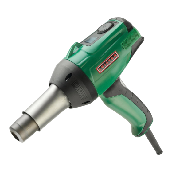
Hot Air Tool
GHIBLI AW
Serial number from 1411191700 (dc1448)
Software version from 3.02
QM
Page
Created
Released
Modified
Tel. +41 41 662 74 74 Fax +41 41 662 74 16
INN_FO_29
1 / 48
13.04.15 PRI
20.04.15 PRI
02.07.18 PRI
leister@leister.com
Advertisement
Table of Contents

Related Manuals for Leister GHIBLI AW


Summary of Contents for Leister GHIBLI AW
- Page 1 © 2018 Leister Technologies AG, CH-6056 Kaegiswil These repair instructions may not be distributed or reproduced in part or in whole in any form without prior written consent from Leister Technologies AG, CH-6056 Kaegiswil. Leister Technologies AG, CH-6056 Kaegiswil / Switzerland Tel.
-
Page 2: Table Of Contents
INN_FO_29 Repair instructions Page 2 / 48 Ghibli AW Created 13.04.15 PRI Leister Technologies AG Released 20.04.15 PRI Revision: B Modified 02.07.18 PRI Table of contents Scope of applicability ...................... 4 Safety precautions ......................4 Remarks ........................... 4 Components naming ....................... 5 Errors and possible causes .................... - Page 3 12.2 Operating parts: e-Drive control button ..............41 12.3 Metal parts: Heater tube, screws................41 13 Cleaning ......................... 41 14 Test procedure for GHIBLI AW (protection class II) ........... 42 14.1 Insulation test ......................42 14.2 Function test ......................42 14.3 Maximum temperature adjustment (optional) ............
-
Page 4: Scope Of Applicability
These repair instructions are reserved exclusively for Leister service centres. Only experi- enced and qualified personnel trained by Leister Technologies AG, CH-6056 Kaegiswil, are allowed to do repair work on Leister tools. Additional national requirements relative to per- sonnel carrying out repair work are to be observed by each service centre. -
Page 5: Components Naming
INN_FO_29 Repair instructions Page 5 / 48 Ghibli AW Created 13.04.15 PRI Leister Technologies AG Released 20.04.15 PRI Revision: B Modified 02.07.18 PRI 4 Components naming Legend 1. Electronic circuit board PTU 2. Electronic circuit board HMI 3. Electronic circuit board HCU (Print adapter front) 4. -
Page 6: Errors And Possible Causes
INN_FO_29 Repair instructions Page 6 / 48 Ghibli AW Created 13.04.15 PRI Leister Technologies AG Released 20.04.15 PRI Revision: B Modified 02.07.18 PRI 5 Errors and possible causes 5.1 No function Error Possible causes Repair methods No function 1. No power supply Check line/mains voltage 2. -
Page 7: Tool Does Not Heat (Correctly), Motor Runs
2. Heating element defec- Replace heating element tive (chapter 9.3) Temperature limit switch 1. Overheating: Ghibli AW Clean air filters (according to oper- is activated or defective air flow is too low ating manual) Check nozzle for clogging (clean or Warning "Overheating"... -
Page 8: Motor Does Not Run (Correctly), Tool Heats
3. Line/mains voltage ok, Replace electronic circuit board but incorrectly measured HCU (chapter 10.3) 5.6 Indication of error numbers Exxxh Error number Possible causes Repair methods 1. Ghibli AW displays an Error correction according to error error message list (chapter 17) -
Page 9: Service Menu
Error memory 4 No heating output as long as Ghibli AW is in the service mode menu Numbers of more than 4 digits are displayed as scrolling text Quit service menu by disconnecting tool from the line/mains voltage only (unplug the tool) -
Page 10: Select Service Menu (Enter Service Code)
INN_FO_29 Repair instructions Page 10 / 48 Ghibli AW Created 13.04.15 PRI Leister Technologies AG Released 20.04.15 PRI Revision: B Modified 02.07.18 PRI 6.1 Select service menu (enter service code) Requiring a service code prevents the user to enter the service menu accidentally. -
Page 11: Temperature Unit
Revision: B Modified 02.07.18 PRI 6.3 Temperature unit Ghibli AW enables to display temperatures in °C or °F units. Select °C or °F unit in the ser- vice menu. Menu item "Temperature unit" indicates the currently selected temperature unit Push e-Drive control button shortly to alter... -
Page 12: Nominal Voltage
Modified 02.07.18 PRI 6.4 Nominal voltage Ghibli AW enables nominal voltage selection. The service menu offers nominal voltages of 100V, 120V and 230V. Nominal voltage input defines the limits for under- and overvoltage announcements from line/mains voltage. Menu item "Nominal voltage" indicates the... -
Page 13: Carbon Brushes Operating Time (Reset "Service Recommended")
INN_FO_29 Repair instructions Page 13 / 48 Ghibli AW Created 13.04.15 PRI Leister Technologies AG Released 20.04.15 PRI Revision: B Modified 02.07.18 PRI 6.5 Carbon brushes operating time (reset "Service recommended") The carbon brushes operating time counts back from a recommended op- erating time to zero. -
Page 14: Tool Operating Hours
6.7 Number of operation activations Ghibli AW increases the number of operation activations with each connection of the tool to the line/mains (and pushing e-Drive control button for a long time blower motor runs). Menu item "Number of operation activa- tions"... -
Page 15: Maximum Temperature Adjustment
Modified 02.07.18 PRI 6.9 Maximum temperature adjustment Ghibli AW offers the possibility to adjust the maximum temperature. This is an optional pro- cedure and not compulsory during service work. Adjustment procedure is described in chapter 14.3. Menu item "Temperature adjust" (Adjust) -
Page 16: Error Code Memory
INN_FO_29 Repair instructions Page 16 / 48 Ghibli AW Created 13.04.15 PRI Leister Technologies AG Released 20.04.15 PRI Revision: B Modified 02.07.18 PRI 6.10 Error code memory The error code memory enables a previous history access for analysis purposes. Detailed descriptions of the error codes are given in chapter 17 "Error codes and repair methods". -
Page 17: Bossmode Menu
INN_FO_29 Repair instructions Page 17 / 48 Ghibli AW Created 13.04.15 PRI Leister Technologies AG Released 20.04.15 PRI Revision: B Modified 02.07.18 PRI 7 BossMode menu Caution: BossMode menu requires the tool to be connected to line/mains voltage! BossMode menu is intended to limit user adjustments (temperature and/or air flow). - Page 18 INN_FO_29 Repair instructions Page 18 / 48 Ghibli AW Created 13.04.15 PRI Leister Technologies AG Released 20.04.15 PRI Revision: B Modified 02.07.18 PRI Save selected mode by pushing e-Drive control button for a long time (flashing dis- play changes to static display).
-
Page 19: Tool Opening / Assembling
INN_FO_29 Repair instructions Page 19 / 48 Ghibli AW Created 13.04.15 PRI Leister Technologies AG Released 20.04.15 PRI Revision: B Modified 02.07.18 PRI 8 Tool opening / assembling Caution! Disconnect tool from the line/mains before any work is commenced! Following tools will be needed for repair work: ... -
Page 20: Tool Assembling
INN_FO_29 Repair instructions Page 20 / 48 Ghibli AW Created 13.04.15 PRI Leister Technologies AG Released 20.04.15 PRI Revision: B Modified 02.07.18 PRI 8.2 Tool assembling Check mechanical parts for abrasion before assembling (chapter 12) Fix 4 black flex wires (interconnection of... - Page 21 INN_FO_29 Repair instructions Page 21 / 48 Ghibli AW Created 13.04.15 PRI Leister Technologies AG Released 20.04.15 PRI Revision: B Modified 02.07.18 PRI Assemble heating element over thermocou- ple; during insertion in blower housing top make sure, the electrical contacts fit properly...
-
Page 22: Electric Components
INN_FO_29 Repair instructions Page 22 / 48 Ghibli AW Created 13.04.15 PRI Leister Technologies AG Released 20.04.15 PRI Revision: B Modified 02.07.18 PRI 9 Electric components Caution! Disconnect tool from the line/mains before any work is commenced! 9.1 Power supply cord ... - Page 23 INN_FO_29 Repair instructions Page 23 / 48 Ghibli AW Created 13.04.15 PRI Leister Technologies AG Released 20.04.15 PRI Revision: B Modified 02.07.18 PRI Extract power supply cord from strain relief clamps Disconnect power supply cord from termi- nals: Push slotted screw driver size 0 in...
-
Page 24: Internal Wiring
INN_FO_29 Repair instructions Page 24 / 48 Ghibli AW Created 13.04.15 PRI Leister Technologies AG Released 20.04.15 PRI Revision: B Modified 02.07.18 PRI 9.2 Internal wiring Check correct wiring; terminals and flex wires are of the same color (compare with illustra- tions) ... -
Page 25: Heating Element
INN_FO_29 Repair instructions Page 25 / 48 Ghibli AW Created 13.04.15 PRI Leister Technologies AG Released 20.04.15 PRI Revision: B Modified 02.07.18 PRI 9.3 Heating element Check ceramic parts for mechanical damages and overheating indications If heating channels are clogged, try to clear them by using compressed air ... -
Page 26: Thermocouple
INN_FO_29 Repair instructions Page 26 / 48 Ghibli AW Created 13.04.15 PRI Leister Technologies AG Released 20.04.15 PRI Revision: B Modified 02.07.18 PRI 9.4 Thermocouple Check thermocouple for mechanical damage and correct connection Check function of thermocouple Visual inspection, thermometer, hot air tool, continuity checker/buzzer Replace thermocouple if it is mechanically damaged or shows a malfunction. - Page 27 INN_FO_29 Repair instructions Page 27 / 48 Ghibli AW Created 13.04.15 PRI Leister Technologies AG Released 20.04.15 PRI Revision: B Modified 02.07.18 PRI Check thermocouple for mechanical damage Check correct connection of thermocouple (observe color code; short circuits caused by untwisted ends of flex wires) Check correct function of thermocouple ...
-
Page 28: Electronic Circuit Boards
INN_FO_29 Repair instructions Page 28 / 48 Ghibli AW Created 13.04.15 PRI Leister Technologies AG Released 20.04.15 PRI Revision: B Modified 02.07.18 PRI 10 Electronic circuit boards Caution! The following measurement sometimes requires the tool to be connected to line/mains. Insure tool is disconnected from line/mains before any work is com- menced! 10.1 Function check... - Page 29 INN_FO_29 Repair instructions Page 29 / 48 Ghibli AW Created 13.04.15 PRI Leister Technologies AG Released 20.04.15 PRI Revision: B Modified 02.07.18 PRI Disconnect power supply (blue and brown flex wire): Push slotted screw driver, size 0, in terminals; extract flex wires Disconnect signal lines: Push terminal lev- ers with a screw driver;...
-
Page 30: Replacement Of Electronic Circuit Board Ptu
INN_FO_29 Repair instructions Page 30 / 48 Ghibli AW Created 13.04.15 PRI Leister Technologies AG Released 20.04.15 PRI Revision: B Modified 02.07.18 PRI 10.4 Replacement of electronic circuit board PTU Open tool according to chapter 8.1 Turn print adapter front up... - Page 31 INN_FO_29 Repair instructions Page 31 / 48 Ghibli AW Created 13.04.15 PRI Leister Technologies AG Released 20.04.15 PRI Revision: B Modified 02.07.18 PRI Disconnect power supply (blue and brown flex wire): Push slotted screw driver, size 0, in terminals; extract flex wires...
-
Page 32: Replacement Of Electronic Circuit Board Hmi
INN_FO_29 Repair instructions Page 32 / 48 Ghibli AW Created 13.04.15 PRI Leister Technologies AG Released 20.04.15 PRI Revision: B Modified 02.07.18 PRI 10.5 Replacement of electronic circuit board HMI Open tool according to chapter 8.1 Turn print adapter front up... - Page 33 INN_FO_29 Repair instructions Page 33 / 48 Ghibli AW Created 13.04.15 PRI Leister Technologies AG Released 20.04.15 PRI Revision: B Modified 02.07.18 PRI Extract signal lines between housing shell and attachment ring Extract electronic circuit board HMI from housing shell Reassemble tool in reverse order;...
- Page 34 When switching on the tool for the first time after replacement of the electronic circuit HMI, its software requires an initial operation test [TEST 2]. No nozzle attached! Connect Ghibli AW to rated voltage (ac- cording to nameplate) Display shows "TEST 2" (initial operation);...
- Page 35 By pushing e-Drive control button for a long time nominal voltage will be saved and tool starts heating Ghibli AW heats with maximum power (possibly reduced by heating element pro- tection), blower unit runs on position 4, dis- play shows thermocouple temperature with no respect to ambient temperature;...
-
Page 36: Blower Unit (Motor)
INN_FO_29 Repair instructions Page 36 / 48 Ghibli AW Created 13.04.15 PRI Leister Technologies AG Released 20.04.15 PRI Revision: B Modified 02.07.18 PRI 11 Blower unit (motor) 11.1 Commutator Check commutator: Worn out lamella Bluish discoloration Deep groove (U-shaped) If a commutator defect is detected, replace motor (see chapter 11.4) -
Page 37: Carbon Brushes
INN_FO_29 Repair instructions Page 37 / 48 Ghibli AW Created 13.04.15 PRI Leister Technologies AG Released 20.04.15 PRI Revision: B Modified 02.07.18 PRI 11.3 Carbon brushes Remove carbon brushes, measure its length and replace them if their length measures 4mm or even less. -
Page 38: Motor
INN_FO_29 Repair instructions Page 38 / 48 Ghibli AW Created 13.04.15 PRI Leister Technologies AG Released 20.04.15 PRI Revision: B Modified 02.07.18 PRI 11.4 Motor Open tool according to chapter 8.1 Turn print adapter front up Extract motor from attachment ring... -
Page 39: Impellers
INN_FO_29 Repair instructions Page 39 / 48 Ghibli AW Created 13.04.15 PRI Leister Technologies AG Released 20.04.15 PRI Revision: B Modified 02.07.18 PRI 11.5 Impellers Cleaning: Clean polluted impellers by using compressed air (not in direction of motor bear- ing) Positioning: If vibrations occur, slightly loosen hexagon nut, rotate impellers against each other and fasten hexagon nut;... - Page 40 INN_FO_29 Repair instructions Page 40 / 48 Ghibli AW Created 13.04.15 PRI Leister Technologies AG Released 20.04.15 PRI Revision: B Modified 02.07.18 PRI Remove deflector Push the lower impeller to the top by using two slim screw drivers; as soon as it is enough far from the bottom it may be re- moved the same way as the upper impeller.
-
Page 41: Mechanical Parts
INN_FO_29 Repair instructions Page 41 / 48 Ghibli AW Created 13.04.15 PRI Leister Technologies AG Released 20.04.15 PRI Revision: B Modified 02.07.18 PRI 12 Mechanical parts 12.1 Housing parts: Housing shells, air filter and blower housing top Replace housing shells and/or blower housing top if these parts are fairly worn out (abrasion,... -
Page 42: Test Procedure For Ghibli Aw (Protection Class Ii)
20.04.15 PRI Revision: B Modified 02.07.18 PRI 14 Test procedure for GHIBLI AW (protection class II) 14.1 Insulation test Function test of the high voltage tester: Short-circuiting tips Signal lamp illuminates and horn sounds Apply a high voltage of 2500V (release current < 30mA) for 1 second between line/mains plug and protection tube of the heater tube;... - Page 43 INN_FO_29 Repair instructions Page 43 / 48 Ghibli AW Created 13.04.15 PRI Leister Technologies AG Released 20.04.15 PRI Revision: B Modified 02.07.18 PRI Wait for 5 minutes until set temperature is achieved; no error or warning message may occur Check air output temperature: Insert exter-...
-
Page 44: Maximum Temperature Adjustment (Optional)
0000: consecutive number Company label LEISTER must be neatly printed on the handle Check power supply cord mechanically and electrically (correct plug type for country, conductor cross-section as per rated current) ... -
Page 45: Wiring Diagram
L1 brown L1 brown 100…230V N blue N blue Motor B 47/25 16 Equipment required for Leister repair service 16.1 Mobile equipment 1 protective earth conductor tester (e.g. Elabo) 1 high voltage tester up to 4000V (e.g. Elabo, Korntal) ... -
Page 46: Error Messages And Repair Methods
02.07.18 PRI 17 Error messages and repair methods Ghibli AW display indicates error messages as hex codes. They are saved in the error code memory (select error code memory see chapter 6.10). Several error codes are not displayed as hex codes, but with special views (see column "Reason"). - Page 47 6.) Replace electronic circuit board HCU (chapter 10.3) E011h Missing calibration of elec- No calibration of print adapter front report with error code to Leister Switzerland tronic circuit board HCU 1.) Replace electronic circuit board HCU (chapter 10.3) Missing configuration of...
- Page 48 E00Fh (initial value of thermocouple temperature) o E010h (final value of thermocouple temperature) Please report following errors (including error code) to Leister Switzerland service centre: o E011h (missing calibration print adapter front) o E013h (missing configuration print adapter front)
Need help?
Do you have a question about the GHIBLI AW and is the answer not in the manual?
Questions and answers