
Related Manuals for Clarke STRONG-ARM CCL2250


Summary of Contents for Clarke STRONG-ARM CCL2250
- Page 1 HYDRAULIC CAR LIFT MODEL NO: CCL2250 PART NO: 7610146 OPERATION & MAINTENANCE INSTRUCTIONS ORIGINAL INSTRUCTIONS GC-01/23...
-
Page 2: Specifications
INTRODUCTION Thank you for purchasing this CLARKE Car Lift. Before attempting to operate this product, it is essential that you read this manual thoroughly and carefully follow all instructions given. In doing so you can look forward to the product giving you long and satisfactory service. -
Page 3: General Safety Rules
GENERAL SAFETY RULES CAUTION: FAILURE TO FOLLOW THESE PRECAUTIONS COULD RESULT IN PERSONAL INJURY, AND/OR DAMAGE TO PROPERTY. LIFTING OPERATIONS AND LIFTING EQUIPMENT REGULATIONS 1998 This lift may fall within the scope of LOLER. It is the owner’s responsibility to determine whether or not it does and, if so, to comply with any applicable requirements in LOLER, for having the lift thoroughly examined. -
Page 4: Electrical Safety
ELECTRICAL SAFETY 1. Power plugs must match the outlet. NEVER modify the plug in any way. DO NOT use adapter plugs with earthed (grounded) power products. Correct plugs and matching outlets will reduce the risk of electric shock. 2. DO NOT abuse the cable. Keep the cable away from heat, oil, sharp edges or moving parts. -
Page 5: Environmental Protection
Scissor lifts are designed to only hold loads with the locking bars in the safety locking positions. 17. ALWAYS use spare parts supplied by CLARKE International. Using non- standard parts could be extremely dangerous. Please keep these instructions in a safe place for future reference. -
Page 6: Electrical Connections
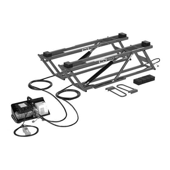
ELECTRICAL CONNECTIONS WARNING! READ THESE ELECTRICAL SAFETY INSTRUCTIONS THOROUGHLY BEFORE CONNECTING THE MACHINE TO THE MAINS SUPPLY. Before switching the product on, make sure that the voltage of your electricity supply is the same as that indicated on the rating plate. This product is designed to operate on 230VAC 50Hz. - Page 7 OVERVIEW & INVENTORY 1. Filler plug for hydraulic fluid 2. Hydraulic fluid reservoir 3. Long hydraulic hoses with couplers (x2) 4. Lifting frames (x2) 5. Safety lock bar (x2) 6. Short hydraulic hoses with couplers (x2) 7. Rubber lifting blocks 55mm (X4) and 75mm (x4) 8.
-
Page 8: Assembly And Preparation
Unpack the components and remove packing materials. Check to ensure that no damage has occurred during transit. Before proceeding, please check contents against the inventory list and immediately advise the CLARKE dealer where you purchased the product if any parts are missing. Refer also to the inventory on page 7. - Page 9 4. Connect the male couplers on the long hoses to the female couplers on the short hose. 5. Connect the power unit to the power supply. • The lift is now ready to use. 6. Press the U button (up) on the remote control (8) to lift and the D button (Down) to lower.
- Page 10 OPERATION AND LIFTING PROCEDURE POSITIONING THE LIFTING FRAMES IMPORTANT: • Before positioning the lifting frames, check that both frames are fully lowered and that the work area is free from obstacles. • Check that the vehicle is well balanced and cannot tip in any direction. •...
- Page 11 4. Adjust the lifting blocks on the plates so that they are directly beneath the vehicle’s lifting points. • In this way, the lifting frames and lifting blocks are correctly positioned to lift the vehicle. IMPORTANT: The lifting frames must be in parallel under the vehicle.
- Page 12 This lift has three locking positions: • A. Tracks. • B. Lower Locking Position. • C. The Turning Block MUST remain in the tracks. • D. Middle Locking Position. • E. Upper Locking Position. DO NOT leave the lift unattended if is not fully lowered or locked in one of the three locked positions.
- Page 13 6. Check that the lifting blocks are located at the vehicle’s lifting points. If the lifting blocks are correctly positioned, continue lifting. If the lifting blocks are not correctly positioned, press the D button on the remote control to lower the vehicle and make the necessary adjustments.
- Page 14 LOWERING THE FRAMES FROM THE LOCKED POSITION WARNING: WHEN LOWERING THE FRAMES, MAKE SURE THE LOCKING BAR AND THE TURNING BLOCK STAY IN THEIR TRACKS. IF THEY GET KNOCKED SIDEWAYS, FOR EXAMPLE, THEY CAN GET STUCK ON THE RAIL OF THE TRACK WHICH COULD RESULT IN THE LIFT NOT LOWERING CORRECTLY.
-
Page 15: Maintenance
MAINTENANCE WARNING: ISOLATE THE POWER SUPPLY AND RELIEVE THE HYDRAULIC PRESSURE PRIOR TO ANY MAINTENANCE AND/OR CLEANING. Relieve pressure by holding the D button for a few seconds after the lifting frames have been fully lowered, in order to return as much hydraulic fluid to the fluid reservoir. CHECKS BEFORE USE •... -
Page 16: Moving And Storage
Store the lift fully lowered when not in use. REPAIRS Contact your CLARKE dealer for technical assistance or repairs. The warranty will be invalidated if the product is damaged as a result of an accident, negligence or incorrect use, or if it has been repaired by unauthorised personnel. -
Page 17: Troubleshooting
The power unit fails to deliver Send the power unit for repair or contact any pressure your CLARKE dealer. Lifting frames cannot be raised There must be space between the ground from a fully lowered position... -
Page 18: Component Parts
COMPONENT PARTS ESCRIPTION ESCRIPTION Lift frame A Short hose Lift frame B Long hose Frame handle Power unit Locking bar A Female coupler Hydraulic cylinder Male coupler Rubber lift blocks (3”) Wheel Rubber lift blocks (2”) Locking bar B Fitting Controller assembly Parts &... -
Page 19: Declarations Of Conformity
DECLARATIONS OF CONFORMITY Parts & Service: 020 8988 7400 / E-mail: Parts@clarkeinternational.com or Service@clarkeinternational.com...
Need help?
Do you have a question about the STRONG-ARM CCL2250 and is the answer not in the manual?
Questions and answers