
Related Manuals for Clarke CML5


Summary of Contents for Clarke CML5
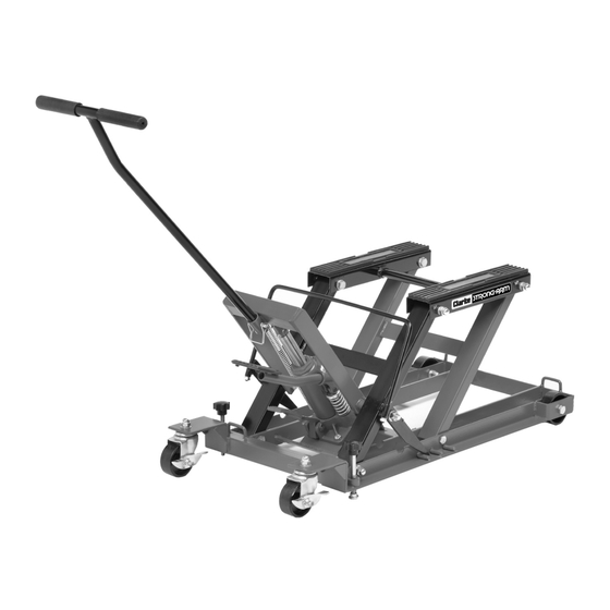
- Page 1 HYDRAULIC MOTORCYCLE LIFT MODEL NO: CML5 PART NO: 7610193 OPERATION & MAINTENANCE INSTRUCTIONS LS0713...
-
Page 2: Specifications
GUARANTEE This CLARKE product is guaranteed against faulty manufacture for a period of 12 months from the date of purchase. Please keep your receipt as proof of purchase. -
Page 3: Safety Precautions
8. ALWAYS inspect the lift before use to ensure it is in good condition, and replace any damaged or worn parts. 9. ALWAYS use spare parts supplied by Clarke International. Using non- standard parts could be extremely dangerous. 10. ENSURE the operator is trained in both operational and safety aspects. -
Page 4: The Ram Assembly
OVERVIEW ASSEMBLY THE RAM ASSEMBLY 1. Secure the ram assembly to its baseplate using the two M8x25 bolts and M8 Spring washers supplied. 2. Tighten the bolts securely. Parts & Service: 020 8988 7400 / E-mail: Parts@clarkeinternational.com or Service@clarkeinternational.com... -
Page 5: The Locking Bar
THE LOCKING BAR 1. Locate the locking bar handle in to the socket at each side of the lift. 2. Place a M8 spring washer on to the threads and screw on the M8 nut securely. • Ensure the locking bar is free to rotate under its own weight. -
Page 6: The Handle And Operating Pedal
THE HANDLE AND OPERATING PEDAL The handle is secured to the frame using the pin provided. The operating pedal should be slid into place and secured using the M8x12 bolt supplied. OPERATION NOTE: The operator must be able to watch the lift and the load during all movements. - Page 7 3. When the motorcycle is satisfactorily supported and completely stable, screw down the two stabilisers, • This reduces any load from the castors, 4. Raise the load slowlyby pumping the operating pedal. 5. At all times make sure that the moter cycle is fully supported and stable.
-
Page 8: Lowering The Load
If necessary, consult your Clarke dealer. If any Warning labels becomes illegible, have it replaced. Contact your Clarke dealer. REPAIR Should any repairs be required they should be carried out by qualified service engineers, cantact the Clarke Service department on 020 8988 7400. -
Page 9: Parts List
PARTS LIST MAIN UNIT ESCRIPTION ESCRIPTION NUMBER NUMBER Base HTCML5A Pump Spring HTCML5L Link HTCML5B Lock Rear Castor Assembly HTCML5M Lift Saddle HTCML5C Height Lock Bar HTCML5N Height Lock Release HTCML5D Front Wheel Assembly HTCML5O Connecting Rod HTCML5E Loops HTCML5P T - Handle HTCML5F Clip... -
Page 10: Part Diagram
PART DIAGRAM Parts & Service: 020 8988 7400 / E-mail: Parts@clarkeinternational.com or Service@clarkeinternational.com... -
Page 11: Declaration Of Conformity
DECLARATION OF CONFORMITY Parts & Service: 020 8988 7400 / E-mail: Parts@clarkeinternational.com or Service@clarkeinternational.com...
Need help?
Do you have a question about the CML5 and is the answer not in the manual?
Questions and answers
Can you buy the handle like a jack handle and how much