MR MSENSE BM Operating Instructions Manual
Monitoring system
Hide thumbs
Also See for MSENSE BM:
- Operating instructions manual (164 pages) ,
- Operating instructions manual (190 pages)
Table of Contents
Advertisement
Quick Links
Advertisement
Table of Contents

Related Manuals for MR MSENSE BM


Summary of Contents for MR MSENSE BM
- Page 1 Monitoring system ® MSENSE Operating instructions 5089542/12 EN...
- Page 2 © All rights reserved by Maschinenfabrik Reinhausen Dissemination and reproduction of this document and use and disclosure of its content are strictly prohibited unless expressly permitted. Infringements will result in liability for compensation. All rights reserved in the event of the granting of patents, utility models or designs.
-
Page 3: Table Of Contents
Table of contents Table of contents Introduction......................... 9 Manufacturer............................ 9 Completeness............................. 9 Safekeeping............................ 9 Notation conventions .......................... 9 1.4.1 Hazard communication system .......................... 9 1.4.2 Information system.............................. 11 1.4.3 Instruction system ............................... 11 1.4.4 Typographic conventions ............................ 12 Safety.......................... 13 Appropriate use .......................... 13 Inappropriate use.......................... - Page 4 Table of contents Packaging, transport and storage .................. 44 Packaging ............................ 44 5.1.1 Suitability................................ 44 5.1.2 Markings................................ 45 Transportation, receipt and handling of shipments................ 46 Storage of shipments........................ 47 Unpacking shipments and checking for transportation damages ............. 48 Mounting ........................... 51 Preparation ............................ 51 Installing the bushing adapter......................
- Page 5 Table of contents Determining the capacitance and dissipation factor of the bushings with BM-T....... 93 Setting the language......................... 93 Setting date and time........................ 94 Setting the parameters ........................ 94 7.5.1 Commissioning wizard ............................ 94 7.5.2 Setting the parameters manually ........................ 95 Performing standardization....................... 97 Performing tests..........................
- Page 6 Table of contents 8.11 Linking signals and events...................... 142 8.11.1 Linking digital outputs............................ 142 8.11.2 Linking control system messages ........................ 143 8.12 Setting the transformer data for the reference system (optional) ........... 145 8.13 Circuit breaker monitoring....................... 146 8.14 Configuring bushing monitoring ...................... 146 8.14.1 Set the field designation............................ 146 8.14.2...
- Page 7 Table of contents 8.26 Transformer Personal Logic Editor (TPLE).................. 182 8.26.1 Function ................................ 182 8.26.2 Configuring TPLE.............................. 195 Inspection and maintenance .................. 199 Care .............................. 199 Inspection ............................ 199 Maintenance ........................... 199 Fault elimination ...................... 200 10.1 General faults .......................... 200 10.2 Signal lights and digital outputs ......................
- Page 8 Table of contents 14.3 Dimensional drawings........................ 240 14.3.1 101335000 ................................ 241 14.3.2 101358630 ................................ 242 14.3.3 101334980 ................................ 243 14.3.4 101358640 ................................ 244 Glossary .......................... 245 List of key words ...................... 246 ® MSENSE 5089542/12 EN Maschinenfabrik Reinhausen GmbH 2022...
-
Page 9: Introduction
Germany Tel.: +49 941 4090-0 E-mail: sales@reinhausen.com Internet: www.reinhausen.com MR Reinhausen customer portal: https://portal.reinhausen.com Further information on the product and copies of this technical file are avail- able from this address if required. 1.2 Completeness This technical file is incomplete without the supporting documents. - Page 10 1 Introduction Type of danger! WARNING Source of the danger and outcome. ► Action ► Action 1.4.1.2 Embedded warning information Embedded warnings refer to a particular part within a section. These warn- ings apply to smaller units of information than the warnings relating to sec- tions.
-
Page 11: Information System
1 Introduction Pictogram Definition Warning of danger of tipping Warning of danger of crushing Table 2: Pictograms used in warning notices 1.4.2 Information system Information is designed to simplify and improve understanding of particular procedures. In this technical file it is laid out as follows: Important information. -
Page 12: Typographic Conventions
1 Introduction 2. Step 2. ð Result of step (optional). ð Result of action (optional). 1.4.4 Typographic conventions Typographic convention Purpose Example UPPERCASE Operating controls, switches ON/OFF [Brackets] PC keyboard [Ctrl] + [Alt] Bold Software operating controls Press Continue button …>…>…... -
Page 13: Safety
2 Safety 2 Safety ▪ Read this technical file through to familiarize yourself with the product. ▪ This technical file is a part of the product. ▪ Read and observe the safety instructions provided in this chapter. ▪ Read and observe the warnings in this technical file in order to avoid func- tion-related dangers. -
Page 14: Inappropriate Use
2 Safety ▪ Only use the equipment and special tools included in the scope of delivery for the intended purpose and in accordance with the specifications of this technical document. ▪ Only operate the product in industrial areas. Observe the notices in this technical file regarding electromagnetic compatibility and the technical data. - Page 15 2 Safety Spare parts Spare parts not approved by Maschinenfabrik Reinhausen GmbH may lead to physical injury, damage to the product and malfunctions. ▪ Only use spare parts that have been approved by Maschinenfabrik Rein- hausen GmbH. ▪ Contact Maschinenfabrik Reinhausen GmbH. Explosion protection Highly flammable or explosive gases, vapors and dusts can cause serious explosions and fire.
-
Page 16: Personnel Qualification
2 Safety Handling test taps on high voltage bushings Test taps on high-voltage bushings must not be operated when open, as the voltages that occur can destroy the equipment. ▪ Close the test tap (= test connection of the bushing) with the original safety cap to ensure grounding, or: ▪... -
Page 17: Personal Protective Equipment
2 Safety Electrically skilled person The electrically skilled person has a technical qualification and therefore has the required knowledge and experience, and is also conversant with the ap- plicable standards and regulations. The electrically skilled person is also pro- ficient in the following: ▪... - Page 18 2 Safety Protective clothing Close-fitting work clothing with a low tearing strength, with tight sleeves and with no protruding parts. It mainly serves to protect the wearer against being caught by moving machine parts. Safety shoes To protect against falling heavy objects and slipping on slippery surfaces.
-
Page 19: Security
3 IT security 3 IT security Observe the following recommendations to operate the product safely. 3.1 General ▪ Ensure that only authorized personnel have access to the device. ▪ Only use the device within an ESP (electronic security perimeter). Do not connect the device to the Internet in an unprotected state. -
Page 20: Operation
3 IT security 3.3 Operation Observe the following recommendations during device operation: ▪ Change the password at regular intervals. ▪ Export the security log [►Section 8.24.1, Page 176] at regular intervals. ▪ Check the log files regularly for unauthorized system access and other se- curity-related events. - Page 21 ETH 2.x (only for MR service) ETH 2.x HTTP for web-based visualization ETH 2.x HTTPS for web-based visualization ETH 2.x FTPS (only for MR service) ETH 2.x 8080 HTTP for web-based visualization ETH 2.x 8081 HTTPS for web-based visualization ETH 2.x SNMP Table 5: Interfaces and open ports of the CPU assembly...
- Page 22 2404 IEC 60870-5-104 SNTP Bus extension (optional) HTTP for web-based visualization HTTPS for web-based visualization SSH (only for MR Service) UDP/TCP Syslog Serial interface (SCADA) Serial interface (SCADA) Table 7: Interfaces and open ports of the CPU assembly Default setting; if you have modified the port for the control system proto- col, only the set port is open.
-
Page 23: Encryption Standards
3 IT security Figure 4: COM-ETH assembly interfaces Interface Protocol Port Description Table 8: Interfaces and open ports of the COM-ETH assembly 3.5 Encryption standards The device supports the following TLS versions: ▪ TLS 1.0 ▪ TLS 1.1 ▪ TLS 1.2 ® Maschinenfabrik Reinhausen GmbH 2022 5089542/12 EN MSENSE... - Page 24 3 IT security The device uses the following cipher suites for a TLS-secured connection: Key exchange Authentication Encryption Key length Operating Hash func- mode tion ECDHE WITH SHA265 ECDHE ECDSA SHA256 ECDH SHA256 SHA384 Table 9: Cipher suite Not available with TLS version >= 1.2 The device uses the SHA256 hash function to save passwords.
- Page 25 3 IT security ▪ Encryption algorithms: – aes128-ctr – aes128-gcm@openssh.com – chacha20-poly1305@openssh.com ▪ MAC protection: – hmac-sha1 – hmac-sha2-256 – hmac-sha1-etm@openssh.com – hmac-sha2-256-etm@openssh.com ▪ Compression: – None – zlib@openssh.com – Zlib ® Maschinenfabrik Reinhausen GmbH 2022 5089542/12 EN MSENSE...
-
Page 26: Product Description
4 Product description 4 Product description 4.1 MSENSE® BM monitoring system versions The device is available in the following versions: ▪ MSENSE® BM: – Standalone version in the control cabinet – Integration solution in the customer control cabinet (pluggable modules) ▪ ETOS® with MSENSE® BM function: –... -
Page 27: Function Description Of Msense® Bm-T
4 Product description Using the 2/3 reference algorithm implemented, the monitoring system can largely compensate for voltage and temperature fluctuations in the 3-phase system and thus ensure reliable monitoring of the bushings. Figure 5: Operating principle The bushing monitoring with 2/3 reference algorithm is also designed to monitor the bushings in systems in which a measurement of the reference grid voltage is not possible. -
Page 28: Performance Features
4 Product description Change of dissipation factor Δtanδ The system can determine the change of the dissipation factor Δtanδ of the bushings and thus monitor the aging of the bushing. For more information, see section Configuring dissipation factor monitoring [►Section 8.14.3, Page 151]. -
Page 29: Operating Modes
4 Product description – Compensation for the effects of weather – Compensation for voltage fluctuations Only with option BM-T – Compensation for grid asymmetry (only with active reference system measuring) Only with option BM-T ▪ Online monitoring of the bushing using dissipation-factor measurement (reference voltage measurement) –... -
Page 30: Design
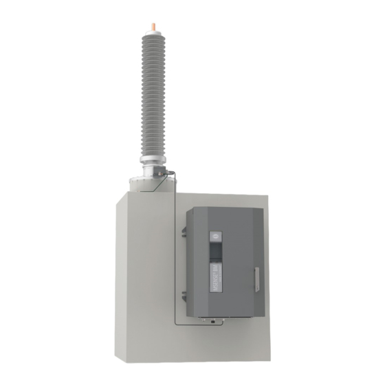
4 Product description 4.7 Design The complete system consists of the following subassemblies: Figure 7: Design 1 Bushing adapter 2 Connection cable for the bushing adapter and bushing coupling unit 3 Bushing coupling unit 4 Connection cable for the bushing coupling unit and control cabinet 5 Control cabinet with monitoring system ®... -
Page 31: Bushing Adapter And Bushing Coupling Unit
4 Product description 4.7.1 Bushing adapter and bushing coupling unit The bushing adapter is used to pick up the measured voltage at the bushing test tap. The downstream bushing coupling unit is used to adjust the mea- sured voltage. Both components are tuned to the bushings to be monitored in accordance with your order. -
Page 32: Ism® Assemblies
4 Product description 4.7.3 ISM® assemblies 4.7.3.1 Power supply 4.7.3.1.1 QS3.241 The G1 PULS DIMENSION QS3.241 assembly supplies power to the ISM® assemblies. Figure 8: PULS DIMENSION QS3.241 assembly 4.7.3.1.2 CP5.241 The PULS DIMENSION CP5.241 assembly supplies power to the ISM® as- semblies. - Page 33 4 Product description 4.7.3.1.3 PS The PS assembly contains the power supply unit for supplying power to the ISM® assemblies. The RY LED signals that the assembly is ready for opera- tion. Figure 10: PS assembly 4.7.3.2 Central processing unit 4.7.3.2.1 CPU I The CPU I assembly is the central processing unit for the device.
- Page 34 4 Product description 4.7.3.2.2 CPU The CPU assembly is the central processing unit for the device. It contains the following interfaces: ▪ Serial interface RS485/422 (electrically isolated) ▪ Internal system interface RS232 ▪ 2x Ethernet 10/100 Mbit (electrically isolated) RS-232 RS-485 Figure 12: CPU assembly 4.7.3.3 Voltage measurement and current measurement 4.7.3.3.1 Voltage measurement...
- Page 35 4 Product description 4.7.3.3.2 U 3 The U3 assembly is used for measuring 3-phase voltage. The RY LED sig- nals that the assembly is ready for operation. Figure 14: U 3 assembly 4.7.3.3.3 I 3 The I 3 assembly is used for measuring 3-phase voltage and current. The RY LED signals that the assembly is ready for operation.
- Page 36 4 Product description 4.7.3.4 Digital inputs and outputs 4.7.3.4.1 DIO 28-15 The DIO 28-15 assembly makes 28 inputs and 15 outputs (6 N/O contacts, 9 change-over contacts) available. Figure 16: DIO 28-15 assembly Warning of a danger point. Read the information given in the product oper- ating instructions.
- Page 37 4 Product description 4.7.3.4.2 DI 16-24V The DI 16-24V assembly has 16 digital inputs with a nominal voltage of 24 V DC. The RY LED signals that the assembly is ready for operation. Figure 17: DI 16-24V assembly 4.7.3.4.3 DI 16-48V The DI 16-48V assembly has 16 digital inputs with a nominal voltage of 48 V DC.
- Page 38 4 Product description 4.7.3.4.4 DI 16-110V The DI 16-110V assembly has 16 digital inputs with a nominal voltage of 110 V DC. The RY LED signals that the assembly is ready for operation. Figure 19: DI 16-110V assembly 4.7.3.4.5 DI 16-220V The DI 16-220V assembly has 16 digital inputs with a nominal voltage of 220 V DC.
- Page 39 4 Product description 4.7.3.4.6 DO 8 The DO 8 assembly provides you with 8 digital outputs (relays). The RY LED signals that the assembly is ready for operation. Figure 21: DO 8 assembly 4.7.3.5 Analog inputs and outputs 4.7.3.5.1 AO 4 The AO 4 assembly provides you with 4 analog outputs for issuing measure- ment values (-20...+20 mA, -10...+10 V).
- Page 40 4 Product description 4.7.3.5.2 AI 4-T The AI 4-T assembly provides you with 4 analog inputs for temperature mea- suring (PT100, PT1000). The RY LED signals that the assembly is ready for operation. Figure 23: AI 4-T assembly 4.7.3.5.3 AI 4 The AI 4 assembly provides you with 4 analog inputs for measuring the cur- rent (-20...+20 mA) or voltage (-10...+10 V) of analog sensors.
- Page 41 4 Product description 4.7.3.6 System networking 4.7.3.6.1 MC 2-2 The MC 2-2 assembly is a media converter, which converts 2 electrical con- nections (RJ45) to one fiber-optic cable connection each. Each is converted independently of the other. The following interfaces are available: ▪...
- Page 42 4 Product description The following redundancy functions are available to you according to your order: ▪ PRP (standard setting) ▪ RSTP Figure 26: SW 3-3 assembly 4.7.3.6.3 BEM1/BES1 The assemblies BEM 1 (master) and BES 1 (slave) are bus extension mod- ules which are used to extend the system by one additional busbar with ad- ditional assemblies.
- Page 43 4 Product description 4.7.3.6.4 COM-ETH The COM-ETH assembly provides you with 5 Ethernet interfaces. Figure 28: COM-ETH assembly ® Maschinenfabrik Reinhausen GmbH 2022 5089542/12 EN MSENSE...
-
Page 44: Packaging, Transport And Storage
5 Packaging, transport and storage 5 Packaging, transport and storage 5.1 Packaging The products are sometimes supplied with sealed packaging and sometimes in a dry state, depending on requirements. Sealed packaging surrounds the packaged goods with plastic foil on all sides. -
Page 45: Markings
5 Packaging, transport and storage 5.1.2 Markings The packaging bears a signature with instructions for safe transport and cor- rect storage. The following symbols apply to the shipment of non-hazardous goods. Adherence to these symbols is mandatory. Protect against Fragile Attach lifting Center of mass moisture... -
Page 46: Transportation, Receipt And Handling Of Shipments
5 Packaging, transport and storage 5.2 Transportation, receipt and handling of shipments WARNING Danger of death or severe injury! Danger of death or serious injuries due to tipping or falling load. ► Only transport the crate when closed. ► Do not remove the securing material used in the crate during transport. ►... -
Page 47: Storage Of Shipments
5 Packaging, transport and storage any circumstances install or commission the packaged goods. Either re- dry the dried packaged goods as per the operating instructions, or contact the manufacturer to agree on how to proceed. ▪ Identify the damaged parts. Hidden damage When damages are not determined until unpacking after receipt of the ship- ment (hidden damage), proceed as follows: ▪... -
Page 48: Unpacking Shipments And Checking For Transportation Damages
5 Packaging, transport and storage If the product is installed more than 6 months after delivery, suitable mea- sures must be taken without delay. The following measures can be used: ▪ Correctly regenerate the drying agent and restore the sealed packaging. ▪... - Page 49 5 Packaging, transport and storage Attachment points for lifting gear WARNING Danger of death and damage to property! Danger of death and damage to property due to tipping or falling load! ► Only trained and authorized persons may select the sling gear and se- cure the load.
- Page 50 5 Packaging, transport and storage ▪ WARNING! Serious injuries due to the control cabinet tipping and damage to the cable gland if the control cabinet is set down, transported or stored upright. Only set down, transport and store the control cabinet on its back.
-
Page 51: Mounting
6 Mounting 6 Mounting This chapter describes how to correctly mount and connect the device. Note the connection diagrams provided. Electric shock! DANGER Risk of fatal injury due to electrical voltage. Always observe the following safety regulations when working in or on electrical equipment. ►... -
Page 52: Installing The Bushing Adapter
1. If the calculated value is outside the target range, replace the bushing coupling unit. 2. Proceed with assembly only if the bushing coupling unit is designed cor- rectly. If in doubt, contact MR. 6.2 Installing the bushing adapter Carry out the operating steps listed below on all bushings. - Page 53 6 Mounting 3. Ensure that the sealing ring of the bushing adapter is present and posi- tioned correctly. Figure 33: Checking the sealing ring (example illustration bushing adapter A001 and A002) Bushing adapter with pin connection ▪ With bushing adapters with a pin port, visually check that the pin of the test tap fits mechanically into the port of the bushing adapter.
- Page 54 6 Mounting Bushing adapter without pin connection ▪ If a spring is supplied with the bushing adapter, use the supplied spring and safely store the spring installed on the test tap. Figure 35: Test tap with spring ▪ If a spring is not supplied with the bushing adapter, use the spring in- stalled on the test tap.
-
Page 55: Installing The Bushing Coupling Unit
6 Mounting Type Tightening torque reference value A001 6 ± 2 Nm A002 30 Nm A003 50 Nm A004 10 Nm A005 25 Nm A006 160 Nm A007 35 Nm A008 5 ± 1 Nm A010 40 Nm Table 14: Tightening torque reference values 6.3 Installing the bushing coupling unit Observe the notes regarding the plausibility check [►Section 6.1, Page 51]. - Page 56 6 Mounting 2. Align the supporting plate so that the grounding symbol is still clearly visi- ble after installation. Insert Allen screws with lock washers into the in- tended holes and fasten the supporting plate on the other side with lock washers and nuts.
-
Page 57: Mounting The Control Cabinet
6 Mounting 5. Install the supporting plate on the bushing flange. Figure 40: Installing the supporting plate on the bushing flange 6. Connect the earthing cable to the supporting plate and transformer. Figure 41: Connecting the earthing cable 6.4 Mounting the control cabinet WARNING Danger of death and damage to property! Danger of death and damage to property due to tipping or falling load! - Page 58 6 Mounting The control cabinet has four fixing attachments on the rear to secure it. 1. Attach four stud bolts (not supplied by MR) to the transformer tank. Rec- ommended clearance between the control cabinet and floor is approx. 0.5…1 m.
- Page 59 6 Mounting Figure 44: Maximum permissible cable angle for the lifting gear limit stop of the control cabinet 4. Use the fixing attachments to attach the control cabinet to the stud bolts and align it vertically on the transformer tank. Figure 45: Attaching the control cabinet ®...
- Page 60 6 Mounting NOTICE! Damage to the control cabinet due to mechanical tension if the offset to the plane is greater than 5 mm. The offset must be compensated using washers. Secure the control cabinet without subjecting it to mechan- ical tension. Figure 46: Securing the drive ®...
-
Page 61: Installing The Cap Rail Modules
6 Mounting 6. Connect the grounding cable to the control cabinet and transformer tank. Figure 47: Connecting the grounding cable 6.5 Installing the cap rail modules With the MSENSE® BM product version as an integration solution in the customer control cabinet, the cap rail modules must be installed in a suitable control cabinet, taking the EMC standards into consideration. -
Page 62: Fastening The Cap Rail
6 Mounting Reliable operation of the device in the permitted temperature range requires that you maintain the following minimum distances to the control cabinet and to neighboring components: Minimum distance To the floor of the control cabinet 88.9 mm (3.5 in) Corresponds to 2 RU To the roof of the control cabinet Between assemblies on the bus bar and as-... -
Page 63: Installing The Bus Rail On The Cap Rail
6 Mounting ► Fasten the cap rail to the rear panel of the switch cabinet using screws and contact washers or lock washers. The distance between the screws may be no more than 10 cm (3.94 in). i n ) ( 3 . ≤... -
Page 64: Installing The Assembly At A Distance On The Cap Rail
6 Mounting 6.5.4 Installing the assembly at a distance on the cap rail The assemblies VI 4, CPU II and AIO 2/AIO 4 are delivered pre-mounted on the bus rail. The following optional assemblies must be mounted with an off- set on a cap rail: ▪... -
Page 65: Wiring The Cpu I / Cpu Ii Assembly
6 Mounting 6.5.5 Wiring the CPU I / CPU II assembly 1. Connect the ETH 2.1 or ETH 2.2 (optional) interface to a PC in accor- dance with the connection diagram to access the web-based visualization. Figure 52: Connection to a PC via Ethernet interface 2. - Page 66 6 Mounting 3. As an alternative to step 2, connect the COM 2 interface (D-Sub 9-pole) to the control system (SCADA) in accordance with the connection diagram. Figure 54: Serial SCADA connection via COM 2 interface Power supply The CPU I or CPU II assembly must be connected to the voltage supply of the voltage supply unit.
-
Page 67: Wiring The Ui Assembly
6 Mounting 2. Insert and fasten the plug into the respective "24 V DC" slot. Figure 56: Fastening the 24 V DC plug 6.5.6 Wiring the UI assembly You must fuse the voltage measurement circuit in accordance with the con- ductor cross section used. You can use the following fuse types: Miniature circuit breaker Safety fuse Standard... - Page 68 6 Mounting To wire the UI assembly, proceed as follows: 1. Guide the cables into the corresponding plug terminals and fasten them using a screwdriver. Figure 57: Example: Plug for voltage measurement Figure 58: Example: Plug for current measurement ® MSENSE 5089542/12 EN Maschinenfabrik Reinhausen GmbH 2022...
-
Page 69: Wiring The Dio Assembly
6 Mounting 2. Insert the plugs into the respective slots and engage the plug. Figure 59: Engaging the plug 6.5.7 Wiring the DIO assembly 1. Guide the leads into the plug terminal in accordance with the supplied connection diagram and fasten them using a screwdriver. Figure 60: Inserting the leads ®... - Page 70 6 Mounting 2. Insert and screw the plug into the respective slot in accordance with the supplied connection diagram. Figure 61: Fastening the plug 3. Connect the DIO 28-15/DIO 42-20 assemblies to CPU I using the CAN bus cable. When connecting the DIO 28-15/DIO 42-20 assembly to the CPU assembly, it is imperative that you use only the supplied connection cable.
- Page 71 6 Mounting Figure 62: CAN bus connection Voltage supply Connect the DIO 28-15/DIO 42-20 assembly to the voltage supply of the voltage supply unit: 1. Guide the leads into the respective plug terminals for the voltage supply and fasten them using a screwdriver. Figure 63: Inserting the leads ®...
- Page 72 6 Mounting 2. Insert and fasten the plug into the respective "24 V DC" slot. Figure 64: Fastening the 24 V DC plug Setting rotary switches of DIO 28-15 and DIO 42-20 If the device has 2 DIO assemblies, you have to ensure that the L rotary switches have different settings on the respective assemblies.
-
Page 73: Wiring The Mc 2-2/Sw3-3 Assembly
6 Mounting Figure 65: Rotary switch H and L of DIO assembly 6.5.8 Wiring the MC 2-2/SW3-3 assembly 1. Insert the supplied SFP module into the corresponding Ethernet interface in accordance with the connection diagram and fold the clasp down. Figure 66: Engaging the SFP module ®... - Page 74 6 Mounting 2. Remove the SFP module dust plug. Figure 67: Removing the dust plug 3. Insert the fiber-optic cable into the SFP module. Figure 68: Inserting the fiber-optic cable ® MSENSE 5089542/12 EN Maschinenfabrik Reinhausen GmbH 2022...
- Page 75 6 Mounting 4. Insert the network cable. Figure 69: Inserting the network cable Voltage supply Connect the MC2-2/SW3-3 assembly to the voltage supply of the voltage supply unit: 1. Guide the leads into the respective plug terminals for the voltage supply and fasten them using a screwdriver.
-
Page 76: Wiring The Qs3.241 Assembly
6 Mounting 2. Insert and fasten the plug into the respective "24V DC" slot. Figure 71: Fastening the 24 V DC plug 6.5.9 Wiring the QS3.241 assembly WARNING Risk of burns and damage to the device! There is a fire hazard if the cables for the 24 V supply to the assemblies are insufficiently dimensioned. - Page 77 6 Mounting Connect the G1 (PULS) assembly in accordance with the connection dia- gram: 1. Insert the leads into the corresponding connections and close the lever Figure 72: Inserting the leads 2. Insert the leads of the neutral conductor (N), phase conductor (L) and pro- tective conductor into the corresponding connections and close the lever...
- Page 78 6 Mounting Figure 73: Inserting the neutral conductor, phase conductor and protective conductor ® MSENSE 5089542/12 EN Maschinenfabrik Reinhausen GmbH 2022...
-
Page 79: Connecting The Device
6 Mounting 6.6 Connecting the device 6.6.1 Cable recommendation Please note the following Maschinenfabrik Reinhausen recommendation when wiring the device. Excessive line capacitance can prevent the relay contacts from interrupting the contact current. In control circuits operated with alternating current, take into account the effect of the line capacitance of long control cables on the function of the relay contacts. - Page 80 6 Mounting RS232 (D-SUB 9-pin) To connect the device via the RS232 interface (COM2), use a data cable with the following structure: Figure 74: RS232 data cable (9-pin) RS485 (D-SUB 9-pin) To connect the device via the RS485 interface (COM2), use a data cable with the following structure: Figure 75: RS485 data cable ®...
-
Page 81: Information About Connecting Serial Interfaces Rs232 And Rs485 (With Rj45 Data Cable)
6 Mounting D-SUB 9-pin plug connection Only use 9-pin D-SUB plugs with the following characteristics: ▪ Plug housing is metallic or metal-plated ▪ Cable shielding is connected with the plug using one of the following two variants: – Shielding is screwed down with traction relief. –... -
Page 82: Information About Laying Fiber-Optic Cable
6 Mounting To connect the device via the RS485/RS232 interface, use a data cable with the following structure: Figure 77: RJ45 data cable 6.6.4 Information about laying fiber-optic cable To ensure the smooth transfer of data via the fiber-optic cable, you must en- sure that mechanical loads are avoided when laying the fiber-optic cable and later on during operation. -
Page 83: Connecting The Bushing Adapter To The Bushing Coupling Unit
6 Mounting 6.6.5 Connecting the bushing adapter to the bushing coupling unit The bushing adapter must be connected to the bushing coupling unit with the connection cable provided. To do so, proceed as follows: 1. Remove the N female connector safety cap from the bushing adapter. 2. -
Page 84: Connecting The Bushing Coupling Unit To The Control Cabinet
6 Mounting 4. Attach the connection cable plug to the bushing coupling unit and screw it in place. Figure 79: Connecting the connection cable to the bushing coupling unit 6.6.6 Connecting the bushing coupling unit to the control cabinet The bushing coupling unit must be connected to the control cabinet with the connection cable provided. - Page 85 6 Mounting 3. Attach the connection cable plug to the U connection of the bushing cou- pling unit and screw it in place. Figure 80: Connecting the connection cable to the bushing coupling unit ® Maschinenfabrik Reinhausen GmbH 2022 5089542/12 EN MSENSE...
- Page 86 6 Mounting NOTICE! Laying the connection cable on the transformer to the control cabinet. While doing so, maintain the minimum permissible bending radius of 50 mm and take precautions to protect the cable from mechanical dam- age (e.g. protective tube). Otherwise, the connection cable may become damaged.
-
Page 87: Connecting The Voltage Transformers For The Reference System
6 Mounting Connecting the connection cable in the control cabinet The connection cable must be connected to the terminal in the control cabi- net in accordance with the connection diagram. You must place the cable shield on the earthing bar using the clamping bracket. 1. - Page 88 6 Mounting To connect the voltage transformers for the reference system, proceed as follows: 1. Remove the cable insulation and crimp a wire end sleeve to the end. Figure 83: Removing the cable insulation 2. Connect the voltage transformers in accordance with the connection dia- gram.
-
Page 89: Connecting Additional Leads (Optional)
6 Mounting 3. Place the cable shield on the earthing bar of the control cabinet using the clamping bracket. Figure 85: Placing the cable shield with clamping bracket on the earthing bar 6.6.8 Connecting additional leads (optional) Connect additional leads as necessary in accordance with the connection di- agram: ▪... - Page 90 6 Mounting Routing information for connecting the control system or visualization When connecting the device to a control system or to your network for ac- cessing the visualization, observe the following recommendation on the ca- ble routing in the control cabinet: ►...
-
Page 91: Connecting The Power Supply
6 Mounting 6.6.9 Connecting the power supply You may only connect the control cabinet to circuits with an external over- current protection device and an isolating device with all poles disconnected so the equipment can be fully de-energized if required (service, maintenance etc.). -
Page 92: Checking Functional Reliability
6 Mounting 6.7 Checking functional reliability To ensure that the device is wired correctly, check its functionality. NOTICE Damage to device and system periphery! An incorrectly connected device can cause damage to the device and sys- tem periphery. ► Check the entire configuration before commissioning. ►... -
Page 93: Commissioning
7 Commissioning 7 Commissioning 7.1 Determining the capacitance of the bushings with BM-C To ensure that the bushings are in the correct condition, Maschinenfabrik Reinhausen GmbH recommends taking an initial measurement on new bushings when commissioning the bushing monitoring. If you are retrofitting the bushing monitoring on bushings already in operation, an initial measure- ment is absolutely essential. -
Page 94: Setting Date And Time
7 Commissioning 2. Select the desired language from the list box. 3. Press the Accept button to save the modified parameter. ð The "Restart device" dialog appears. 4. Restart the device to apply the changed language setting. 7.4 Setting date and time You can set the date and time in the following ways: ▪... -
Page 95: Setting The Parameters Manually
7 Commissioning To set the parameters with the help of the commissioning wizard, proceed as follows: 1. Log in as a user with the necessary access rights. 2. Go to Settings > Commissioning wizard. Figure 89: Calling up the commissioning wizard 3. - Page 96 7 Commissioning 4. C: Set C1 phase L3. 5. C: Set ΔC1 >. 6. C: Set ΔC1 >>. Only with option BM-T Configuring dissipation factor monitoring [►Section 8.14.3, Page 151] 1. tanδ: Activate dissipation factor monitoring. 2. tanδ: Set Δtanδ >. Setting the control system protocol (optional) If you need a control system protocol, you must set the parameters required for this.
-
Page 97: Performing Standardization
▪ Configuring capacitance monitoring [►Section 8.14.2, Page 147] Only with option BM-T ▪ Configuring dissipation factor monitoring [►Section 8.14.3, Page 151] 7.7 Performing tests Please contact Maschinenfabrik Reinhausen GmbH (MR) if any aspect of the tests is not clear. 7.7.1 Ground test For commissioning, carry out a ground test (check of the protective bonding impedance) in accordance with IEC 61010-1. -
Page 98: Performing Function Tests
7 Commissioning Figure 90: BCU ground test 7.7.2 Performing function tests To check that the monitoring system is functioning correctly, proceed as fol- lows: 1. Check the pending event messages [►Section 8.21.1, Page 162]. If event messages are pending, resolve the cause of the event and acknowledge the event. -
Page 99: Dielectric Tests On Transformer Wiring
7 Commissioning ▪ Guide all ground connecting leads to one central connection point (estab- lishment of suitable reference earth). ▪ Disconnect all electronic components before the high voltage test. Before a dielectric test of the wiring, remove all devices with a withstand voltage of < 1,000 V. -
Page 100: Operation
8 Operation 8 Operation This chapter describes all the functions and setting options for the device. 8.1 Establishing a connection to the visualization (with CPU I / CPU II) You can use the ETH 2.1 interface or the optional ETH 2.2 interface of the CPU I or CPU II assembly to establish a connection to the visualization. -
Page 101: Establishing A Connection To The Visualization (With Cpu / Com-Eth)
8 Operation To establish a connection, proceed as follows: 1. Connect the PC and device using an Ethernet cable (RJ45 plug) via the ETH 2.1 or ETH 2.2 interface. Figure 91: Establishing a connection via the ETH 2.1 or ETH 2.2 interface 2. Assign a unique IP address to the PC. This IP address must be in the same subnet as the device (e.g. - Page 102 8 Operation System requirements To access the web-based visualization, you need a PC with an HTML5-ca- pable browser. The display is optimized for the following browsers: ▪ Microsoft Edge ▪ Google Chrome™ To establish a connection, proceed as follows: 1. Connect PC and device via the CPU-X2 or CPU-X3 interface using an Ethernet cable (RJ45 plug).
-
Page 103: Operating Concept
8 Operation Optional COM-ETH assembly If your device is equipped with the optional COM-ETH assembly, you can es- tablish a connection to the visualization via various interfaces. The interfaces do not use a DHCP server. Therefore, you must assign a static IP address to your PC. - Page 104 8 Operation To log out as a user, proceed as follows: ► Press the LOGOUT button in the status line. Navigation If you are operating the device using the web-based visualization, you can navigate by clicking on the appropriate buttons. Example To navigate to the "Date"...
-
Page 105: General
8 Operation Expert mode The device has an expert mode for entering the parameters. You can enter the parameters directly into the overview screen of the respective menu in this mode. Figure 94: Expert mode To activate the expert mode, proceed as follows: 1. -
Page 106: Setting General Device Functions
8 Operation 8.4.1 Setting general device functions You can set general device functions with the following parameters. Settings Parameters General Name Value Home Language English Commissioning wizard Auto-logout Events Time until auto-logout 15.0 min Measured value display Primary values Transformer name Transformer Remote behavior Hardware and SCADA... -
Page 107: Set Up Automatic Logout
8 Operation You can select the following settings: Setting Description Hardware only The device accepts commands through digital inputs. SCADA only The device accepts commands via SCADA. Hardware and SCADA The device accepts commands via digital inputs and SCADA. Table 23: Selecting remote behavior USB interface You can use this parameter to deactivate the USB interface. -
Page 108: Activating/Deactivating Service User Access
8 Operation Auto logout You can use this parameter to activate th automatic logout function. Time until auto logout You can use this parameter to set the time period of inactivity after which a user is automatically logged out. 8.4.3 Activating/deactivating service user access The device is equipped with user access for the Maschinenfabrik Rein- hausen GmbH Technical Service department. -
Page 109: Setting Snmp
8 Operation 5. Restart the device to apply the change. Service user access activation You can use this parameter to activate or deactivate service user access. 8.4.4 Setting SNMP The device supports the SNMP network management protocol (SNMPv1 and SNMPv2c). The protocol uses the port 161/UDP. To use SNMP, you must activate the SNMP agent. -
Page 110: Configuring The Network
8 Operation 8.5 Configuring the network You can use this menu item to configure the network interfaces of the CPU assembly. You can only set the parameters for ETH 1 if the device is equipped with the optional control system connection via Ethernet (TCP/IP): ▪... - Page 111 8 Operation Be sure to enter a valid network mask that is not 0.0.0.0, otherwise it will not be possible to connect to the device. Gateway address ETH 1/ETH 2.2 You can use this parameter to set the gateway's IP address. If you set the value to 0.0.0.0, no gateway is used.
- Page 112 8 Operation DNS server (optional) You can use this parameter to set the IP address of the DNS server. ® MSENSE 5089542/12 EN Maschinenfabrik Reinhausen GmbH 2022...
-
Page 113: Mqtt
8 Operation 8.6 MQTT You can activate and configure the MQTT message protocol in this menu point. To do so, you must connect the device to an MQTT server (Broker) via Ethernet via the ETH 1 or ETH2.x interface on the CPU assembly. Note that the device will only send messages (publish). - Page 114 8 Operation Broker address If you use a URL address, you can use this parameter to enter the domain name of the MQTT server (broker). Otherwise, you can enter the IP address of the MQTT server. Broker port You can use this parameter to set the port of the MQTT server (broker). The following ports are used as standard: ▪...
-
Page 115: Setting The Device Time
8 Operation 8.7 Setting the device time You can set the device time manually or automatically via a time server. The device must be connected to a time server via Ethernet for this purpose. You can operate SNTP and PTP at the same time. In this case, the PTP time is queried in slave operation. - Page 116 8 Operation Synchronization interval You can use this parameter to set the interval at which the device is to call up the time from the time server. Automatic daylight saving / standard time You can use this parameter to activate the automatic switchover between daylight saving time and standard time.
- Page 117 8 Operation PTP hops You can use this parameter to enter the number of network sections be- tween master and slave. You can set up to 16 hops. PTP version You can use this parameter to select the PTP version. ▪...
-
Page 118: Configuring Syslog
8 Operation 8.8 Configuring syslog The device supports the transmission of log messages via the syslog proto- col in accordance with the standards RFC 5424 and RFC 3164. Settings Parameters Syslog Name Value Home Activate syslog Syslog standard RFC 5425 Syslog server 0.0.0.0 Events Syslog server port... - Page 119 8 Operation Syslog server You can use this parameter to set the IP address of the syslog server. Syslog server port You can use this parameter to set the port of the syslog server. Reconnect delay time You can use this parameter to determine how long the device will wait be- fore it attempts to reconnect after the connection has been interrupted earlier or a syslog message could not be transmitted (only for TCP or TLS).
-
Page 120: Scada
8 Operation 8.9 SCADA The following section describes how you can configure the device to connect to a control system (SCADA). You can download the data points with the help of the export manager [►Section 8.24, Page 176]. 8.9.1 Configuring IEC 61850 (optional) If you want to use the IEC 61850 control system protocol, you must set the following parameters. - Page 121 8 Operation 8.9.1.1 Downloading an ICD file You can download the ICD file from the device via the Import/Export Man- ager [►Section 8.24, Page 176]. To do this, you have to establish an Ether- net connection between the device and your PC. 8.9.1.2 Importing CID/SCD file (optional) Note the following definitions for importing a CID file or SCD file.
-
Page 122: Configuring Iec 60870-5-101 (Optional)
8 Operation 8.9.2 Configuring IEC 60870-5-101 (optional) If you want to use the IEC 60870-5-101 control system protocol, you must set the following parameters. Settings Parameters IEC 60870-5-101 Name Value Home Serial interface RS232 Baud rate 9600 Transmission procedure Unbalanced Events Number of link address octets Link address... - Page 123 8 Operation Transmission procedure You can use this parameter to set the transmission procedure. You can se- lect the following options: ▪ Unbalanced transmission ▪ Balanced transmission Number of link address octets You can use this parameter to set how many octets are provided for the link address.
- Page 124 8 Operation ASDU single character confirmation You can use this parameter to set whether a confirmation is to be sent as single characters instead of as a complete message. Single character confir- mation is only possible for requesting data of class 2 (Class 2 Request). RES bit test You can use this parameter to set whether the device is to check the RES bit (Reserved Bit) in the control field.
-
Page 125: Configuring Iec 60870-5-103 (Optional)
8 Operation Reference time You can use this parameter to set which time is to be transmitted by the con- trol system. The device uses this information for time synchronization [►Section 8.7, Page 115]. You can select the following options: Option Description Local... - Page 126 8 Operation Baud rate You can use this parameter to set the serial interface's baud rate. You can select the following options: ▪ 9600 baud ▪ 19200 baud ▪ 38400 baud ▪ 57600 baud ▪ 115200 baud ASDU address You can use this parameter to set the address of the ASDU. Number of data bits You can use this parameter to set the number of databits.
-
Page 127: Configuring Iec 60870-5-104 (Optional)
8 Operation Reference time You can use this parameter to set which time is to be transmitted by the con- trol system. The device uses this information for time synchronization [►Section 8.7, Page 115]. You can select the following options: Option Description Local... - Page 128 8 Operation ASDU address You can use this parameter to set the address of the ASDU. ASDU sequence optimization With this parameter, you can set which method is to be used for optimizing the ASDU types. The standard enables optimization in order to be able to transfer multiple value changes in a telegram in a sequence of ascending in- formation object addresses.
-
Page 129: Configuring Modbus (Optional)
8 Operation Note that all SCADA clients communicate with the device on an equal basis, because the device does not prioritize commands. If you transmit com- mands from several SCADA clients to the device at the same time, the de- vice will execute the last transmitted command. - Page 130 8 Operation Maximum TCP connections You can use this parameter to set the maximum number of TCP connec- tions. TCP Keepalive You can use this parameter to activate/deactivate the "TCP Keepalive" func- tion. Serial interface You can use this parameter to select the serial interface for data transmis- sion.
-
Page 131: Configuring Dnp3 (Optional)
8 Operation 8.9.6 Configuring DNP3 (optional) If you would like to use the DNP3 control system protocol, you must set the parameters listed below. Also refer to the section Configuring the network [►Section 8.5, Page 110] if you want to use the DNP3 via TCP. Settings Parameters DNP3... - Page 132 8 Operation Baud rate You can use this parameter to set the serial interface's baud rate. You can select the following options: ▪ 9600 baud ▪ 19200 baud ▪ 38400 baud ▪ 57600 baud ▪ 115200 baud Device address You can use this parameter to set the device link address. Destination address You can use this parameter to set the destination master link address.
-
Page 133: Configure Data Points (Optional)
8 Operation Reference time You can use this parameter to set which time is to be transmitted by the con- trol system. The device uses this information for time synchronization [►Section 8.7, Page 115]. You can select the following options: Option Description Local... - Page 134 8 Operation Column Description Modifiable Setting range Threshold value for measured values. The data point is 0...32,768 only transferred again if the change of value is greater than the threshold value. ▪ If you enter the value 0, no threshold value is active. ▪...
- Page 135 8 Operation 8.9.7.2 Configuring IEC 60870-5-103 data points You can adjust the following data point properties for the IEC 60870-5-103 control system protocol: Column Description Modifiable Setting range Active You can use the checkbox to set whether the data point is Active/inactive to be transferred via the control system protocol or not.
- Page 136 8 Operation Proceed as follows to configure the data points: 1. Go to Settings > Data point configuration. 2. Adjust the data points as required. 3. Press the Accept button to adopt the modified list of data points. 4. Restart the device to activate the modified list of data points. 8.9.7.3 Configuring IEC 60870-5-104 data points You can adjust the following data point properties for the IEC 60870-5-104 control system protocol:...
- Page 137 8 Operation Figure 111: Configuring IEC 60870-5-104 data points Proceed as follows to configure the data points: 1. Go to Settings > Data point configuration. 2. Adjust the data points as required. 3. Press the Accept button to adopt the modified list of data points. 4.
- Page 138 8 Operation Figure 112: Configuring Modbus data points Proceed as follows to configure the data points: 1. Go to Settings > Data point configuration. 2. Adjust the data points as required. 3. Press the Accept button to adopt the modified list of data points. 4.
- Page 139 8 Operation Column Description Modifiable Setting range PREFSTATICVAR For a data point of class 0 (Static), you can define the fol- 0...6 lowing variation depending on the object group: ▪ BI: 1, 2 ▪ BO: 2 ▪ AI: 2, 4 ▪...
- Page 140 8 Operation Proceed as follows to configure the data points: 1. Go to Settings > Data point configuration. 2. Adjust the data points as required. 3. Press the Accept button to adopt the modified list of data points. 4. Restart the device to activate the modified list of data points. 8.9.7.6 Resetting the data point configuration to factory settings If you want to reset the data point configuration to factory settings, proceed as follows:...
-
Page 141: Setting The Measured Value Recorder
8 Operation 8.10 Setting the measured value recorder Depending on the set average value interval, the measured value recorder can display the measured values over a shorter or longer time period: ▪ Average value interval = 1 s: approx. 1 day and 4 hours ▪... -
Page 142: Linking Signals And Events
8 Operation 8.11 Linking signals and events The device enables you to link digital inputs (GPI) and control system com- mands (SCADA) with device functions, digital outputs (GPO), and control system messages. The digital inputs available are each permanently linked to a Generic digital input event message and the control system commands available are each permanently linked to aGeneric SCADA command event message for this purpose. -
Page 143: Linking Control System Messages
8 Operation Settings Parameters Link outputs Name Value Home Generic digital output 1 Events Information Recorder CHANGE REBOOT admin 04.02.2020 11:14 Settings Figure 115: Linking digital outputs ü The desired event number is known [►Section 8.21, Page 162]. 1. Go to Settings > Parameters > System > Link outputs. 2. - Page 144 8 Operation Settings Parameters Link messages Name Value Home Generic SCADA status message 1 Generic SCADA status message 2 Generic SCADA status message 3 Events Generic SCADA status message 4 Generic SCADA status message 5 Generic SCADA status message 6 Generic SCADA status message 7 Information Generic SCADA status message 8...
-
Page 145: Setting The Transformer Data For The Reference System (Optional)
8 Operation 8.12 Setting the transformer data for the reference system (optional) You can use the following parameters to set the transformer data. You can only access these parameters when the device allows for the measurement of the reference line voltage. If bushing monitoring with the option "Monitoring of 6 bushings"... -
Page 146: Circuit Breaker Monitoring
8 Operation 8.13 Circuit breaker monitoring You can configure up to 4 digital inputs for monitoring the status messages of the circuit breakers in the reference system. This monitoring function is used for detecting whether the reference system is active (circuit breaker in ON position) or inactive (circuit breaker in OFF position). -
Page 147: Configuring Capacitance Monitoring
8 Operation 1. Go to Settings > Parameters > Bushing monitoring > Bushing moni- toring field1/field2. 2. Select the desired parameter. 3. Set the desired parameter. 4. Press the Accept button to save the modified parameter. Field designation You can use this parameter to set the field designation. 8.14.2 Configuring capacitance monitoring The device monitors the amendment in the difference of capacitance C1 be- tween the phases. - Page 148 1,5 Pt, rgb(0,147,214) Min. 8 Operation Min. Max. Analogsignal 0,7 Pt, Pfeil (Voll, 4, 30) ΔC1 ΔC1>> 10 % ΔC1> Figure 119: Capacitance monitoring 1 Status of the bushing C1 Capacitance C1 (gray: ok, yellow/red: limit value exceeded) ΔC1 Capacitance difference ΔC1>...
- Page 149 8 Operation Settings Parameters Bushing ...d 1 Name Value Home F1-C: Activate cap. monitoring F1-C: C1 phase L1 0.6 nF F1-C: C1 phase L2 0.6 nF Events F1-C: C1 phase L3 0.6 nF F1-C: ΔC1 > 5.0 % F1-C: ΔC1 >> 10.0 % F1-C: Perform standardization Information F1-tanδ: Activate diss.
- Page 150 8 Operation F1/F2-C: C1 phase L3 You can use this parameter to set the reference capacitance C1 for the bushings of the L3 phases in field 1 or field 2. The reference value is the value you have measured with an external measuring device for commis- sioning [►Section 7.2, Page 93].
-
Page 151: Configuring Dissipation Factor Monitoring (Msense® Bm-T)
8 Operation F1/F2-C: C BCU phase L3 Set the capacitance of the bushing coupling unit for every field for phase L3. F1/F2-C: Min. measured voltage Set the minimum permitted voltage on the bushing coupling units for bushing capacitance monitoring for every field. F1/F2-C: Standardization min. - Page 152 Max. Arial 9 Pt 1,5 Pt, rgb(0,147,214) 8 Operation Min. You can set a limit value for monitoring the bushings in field 1 or field 2. If Min. Max. Analogsignal 0,7 Pt, Pfeil (Voll, 4, 30) the limit value is exceeded, the monitoring system triggers an event mes- sage and issues a signal at the digital output.
- Page 153 8 Operation Settings Parameters Bushing ...d 1 Name Value Home F1-C: Activate cap. monitoring F1-C: C1 phase L1 0.6 nF F1-C: C1 phase L2 0.6 nF Events F1-C: C1 phase L3 0.6 nF F1-C: ΔC1 > 5.0 % F1-C: ΔC1 >> 10.0 % F1-C: Perform standardization Information F1-tanδ: Activate diss.
-
Page 154: Sum Current Method
8 Operation 8.14.3.3 F1/F2 tanδ: tanδ phase L3 You can use this parameter to set the reference dissipation factor tanδ for the bushing of phase L3 in field 1 or field 2. The reference value is the value you have measured with an external measuring device for commissioning [►Section 7.2, Page 93]. - Page 155 8 Operation Alternatively, you can activate or deactivate the sum current method via digi- tal inputs. While doing so, please note the following: ▪ You must select operating mode REMOTE. ▪ If a high signal is applied to both inputs simultaneously, only the first high signal is taken into account.
-
Page 156: Displaying The State Of The Bushings
8 Operation 8.15 Displaying the state of the bushings The device displays the current state of the bushings and the following mea- sured values: ▪ Status indicator for the bushing based on the set limit values – Gray: Everything OK –... -
Page 157: Displaying The Capacitance Progression
8 Operation 8.16 Displaying the capacitance progression You can display the temporal progression of the capacitance C1 and the ca- pacitance difference ΔC1 over the last 28 days. Figure 124: Capacitance progression ► Go to Information > Bushings > Capacitance C1/ΔC1 field1/field2. 8.17 Show dissipation factor curve (MSENSE®... -
Page 158: Displaying Sum Current Information
8 Operation 8.18 Displaying sum current information If you have activated the sum current method, you can display the recorded values as follows: Field 1/Field 2 sum current The tabular representation shows you the real-time values of the sum cur- rent method for the bushings. -
Page 159: Displaying Measured Value Recorder (Optional)
8 Operation 8.19 Displaying measured value recorder (optional) You can use the optional measured value recorder function to display the progress of measured values and signals over time. If you access it via the web visualization, you can select a maximum of 10 measured values. -
Page 160: Configuring Digital Inputs And Outputs
8 Operation 6. Move the mouse pointer to a measurement point for more information. 7. Use the mouse to produce a selection window or turn the mouse wheel to zoom into or out of the diagram. If necessary, you can move an enlarged diagram with the right mouse button. - Page 161 8 Operation Ensure that the configuration of the digital inputs and outputs is suitable for the functions used. Otherwise, malfunctions may occur in the device and the connected periphery. The following information is displayed in tabular form for configuring the digi- tal inputs and outputs.
-
Page 162: Event Management
8 Operation Creating a backup You need to create a backup to be able to reset the system in the event that any incorrect configuration settings are made. To do so, proceed as follows: 1. Go to Settings > Export. 2. -
Page 163: Configuring Events
8 Operation Acknowledging events Acknowledgeable events must be acknowledged in the event overview so that they are no longer displayed. All other events are automatically removed once the cause is remedied (e.g. limit value is no longer exceeded). To acknowledge the events, proceed as follows: ►... -
Page 164: Displaying Event Memory
8 Operation Settings Events Limit value U< Name Home Limit value U< Description Value has fallen below the limit value for undervoltage U<. Remedy Events Check the current operating conditions of the transformer and the set U< parameters. Information Category Report High active Save... -
Page 165: Exporting The Event Messages Overview
8 Operation To call up the event memory, proceed as follows: 1. Go to Events > Event memory. Figure 134: Event memory 2. Set the desired filters. 3. Select the desired events in the Event list. 4. Press the Search button to display the desired events. Exporting events You can export the event memory entries currently displayed as a csv file. -
Page 166: User Administration
8 Operation 8.22 User administration User administration is based on a system of roles. You must assign a role to every user. You can define access rights to parameters and events for each role. 8.22.1 User roles The access rights to device functions and settings are controlled using a hi- erarchical system of roles. -
Page 167: Changing The Password
Calling up the maintenance wizard Changing tap position table Enabling ECOTAP Modbus Adding sensors to the MR sensor bus Table 45: Access rights permanently linked to the roles 8.22.2 Changing the password All users can change their passwords provided that the user account is not set up as a group account. -
Page 168: Creating, Editing And Deleting Users
8 Operation – Numbers – Special characters To change the password, proceed as follows: 1. Select the user name in the status line. Figure 135: Changing the password 2. Enter the new password twice. 3. Press the Accept button to save the changed password. 8.22.3 Creating, editing and deleting users You can set the following options for all users: ▪... - Page 169 8 Operation Figure 136: Overview of users created You can only create, edit, and delete users if you are assigned an adminis- trator role. When in delivery status, you can log in as the administrator as follows: ▪ User name: admin ▪...
-
Page 170: Setting Access Rights To Parameters And Events
8 Operation Deleting user To delete an existing user, proceed as follows: 1. Go to Settings > Administration > User. 2. In the list, select the button for the desired user. 3. Press the Accept button to delete the user. 8.22.4 Setting access rights to parameters and events You can configure access rights to parameters and events for the available roles. -
Page 171: User Authentication Via Radius (Optional)
VENDOR MR 34559 BEGIN-VENDOR MR # Attributes ATTRIBUTE MR-ISM-User-Group 1 integer # Predefined values for attribute 'MR-ISM-User-Group' VALUE MR-ISM-User-Group Administrator 1 VALUE MR-ISM-User-Group Parameter-configurator 2 VALUE MR-ISM-User-Group Operator 3 VALUE MR-ISM-User-Group Diagnostics 4 VALUE MR-ISM-User-Group Data-display 5... - Page 172 8 Operation 8.22.5.2 Configuring RADIUS To establish a connection to the RADIUS server, you must set the following parameters. Settings Parameters RADIUS Name Value Home Activate RADIUS client RADIUS server 0.0.0.0 RADIUS server port 1812 Events Authentication protocol CHAP Key (shared secret) default Information Recorder...
- Page 173 8 Operation Authentication protocol You can use this parameter to set the authentication protocol through which the server and client communicate. You can select the following options: ▪ PAP (password authentication protocol) ▪ CHAP (challenge handshake protocol) Key (shared secret) You can use this parameter to set the key (shared secret).
-
Page 174: Information About Device
8 Operation 8.23 Information about device 8.23.1 Hardware Under Hardware, you can display information on the device's hardware. You will find information about the signal level of the individual channels for the assemblies. Figure 139: Displaying information for the device's hardware (example) 1. - Page 175 8 Operation ► Go to Information > System > Software. ® Maschinenfabrik Reinhausen GmbH 2022 5089542/12 EN MSENSE...
-
Page 176: Import/Export Manager
Configuration of parameters and events. Data point con- Data point configuration of the control system. figuration Sensor bus de- Sensor description of the sensors for MR sensor bus that have vice descrip- been created with the sensor editor. tion Service data... -
Page 177: Importing Data (Software Version 3.753 And Later)
8 Operation Option Description Security log Logbook of all instances of access and changes relating to secu- rity. RADIUS dictio- Dictionary for importing on a RADIUS server. nary Table 47: Exporting data Only remove the USB stick once the data transfer is complete. Otherwise data may be lost. - Page 178 8 Operation Option Description SCD import Control system configuration import TPLE Customer program import (TPLE). Table 48: Importing data NOTICE Damage to the file system! The file system can become damaged due to an incorrect data transmission process. A damaged file system can lead to the device no longer being functional.
-
Page 179: Configuring Media Converter With Managed Switch
8 Operation 8.25 Configuring media converter with managed switch Observe the following information on configuring the media converter with managed switch SW 3-3. Use the following browser to call up web-based vi- sualization: ▪ Firmware version 02.0.01: Internet Explorer 11 ▪... -
Page 180: Configuration
8 Operation 5. In the Basic settings > Network > Global menu, adjust the network set- tings and click on the Write button. Figure 142: Network settings 6. In the Basic settings > Load/Save menu, click on the Save button to per- manently store the settings. - Page 181 1. Go to Basic settings > Load/Save and click on the Reset to factory de- faults… button. 2. Reestablish the connection to the IP address of 192.168.1.1 if necessary. 3. Set the MR factory settings in accordance with the following table. Menu Parameter...
-
Page 182: Transformer Personal Logic Editor (Tple)
8 Operation 8.26 Transformer Personal Logic Editor (TPLE) You can use the Transformer Personal Logic Editor (TPLE) function to pro- gram simple logical links via the web-based visualization. You can also link the inputs and outputs available on the device using function modules. Note that the device does not meet the requirements of a protective device. - Page 183 8 Operation 8.26.1.3.1 AND Description AND, logical AND link Inputs Input 1…4 (BOOL) Outputs Output (BOOL) Parameter None Function If all configured inputs are TRUE, the output is TRUE, otherwise it is FALSE. Initial state All inputs and outputs are FALSE. Non-configured inputs are assumed to be TRUE.
- Page 184 8 Operation 8.26.1.3.4 NOR Description NOR, logical NOT-OR link Inputs Input 1…4 (BOOL) Outputs Output (BOOL) Parameter None Function If all configured inputs are FALSE, the output is TRUE, otherwise it is FALSE. Initial state All inputs and outputs are FALSE. Non-configured inputs are assumed to be FALSE so that they have no impact on the output.
- Page 185 8 Operation 8.26.1.3.7 Current impulse relay Description RS, current impulse relay Inputs Trigger (BOOL) Set (BOOL) Reset (BOOL) Outputs Output (BOOL) Parameter None Function If the Reset input is TRUE, Output forcibly becomes FALSE. If the Reset input is FALSE and the Set input is TRUE, Output forcibly becomes TRUE.
- Page 186 8 Operation Parameter Time ms (UINT32), 1...1,000,000, default = 1,000 Function If Input has a rising edge, the internal timer is set to zero and starts to run. When the internal timer has reached or exceeded the parameter value, Output becomes TRUE and the counter stops running.
- Page 187 8 Operation Function If there is a rising edge at the Trigger input at any time, the internal timer is set to zero and starts to run, the output becomes TRUE. If the Trigger input becomes FALSE again during the pulse time, this has no impact on the expiration of the pulse time.
- Page 188 8 Operation Function If there is a rising edge at Reset, the output value is set to the value of the Reset value parameter. A rising edge at Reset takes priority over all other inputs. For as long as Lock is TRUE, the pulse signal is not evaluated and the counter reading is retained.
- Page 189 8 Operation Function On Limit ≥ Off Limit setting: ▪ If the value of Input is greater than On Limit, Output becomes TRUE. ▪ If the value of Input is less than or equal to Off Limit, Output becomes FALSE. On Limit <...
- Page 190 8 Operation 8.26.1.3.14 Analog multiplication Description MUL, analog multiplication Inputs Value (REAL32) Multiplier (REAL32) Outputs Result (REAL32) Overflow (BOOL) Parameter Constant multiplier (REAL32), -1,000,000...+1,000,000; default = 1 Function Result = Value * Multiplier * Constant multiplier If the REAL32 range of numbers is exceeded, the Overflow output becomes TRUE.
- Page 191 8 Operation Function Result = Input 1 + Input 2 + Offset If the REAL32 range of numbers is exceeded, the Overflow output becomes TRUE. Initial state All inputs and outputs are zero or FALSE. Table 65: Analog addition function module 8.26.1.3.17 Analog subtraction Description SUB, analog subtraction...
- Page 192 8 Operation 8.26.1.3.20 Average value Description AVRG, average value Inputs Input (REAL32) Enable (BOOL) Reset (BOOL) Autorepeat (BOOL) Outputs Average (REAL32) Done (BOOL) Started (BOOL) SampleCount (UINT32) Parameter Time ms (UINT32): 1...2,000,000,000, default = 10,000 Sample time ms (UINT32): 1...10,000,000, default = 1,000 Function Averaging starts with a rising edge of Enable.
- Page 193 8 Operation Figure 147: AVRG 1 Input 2 Enable 3 Reset 4 AutoRepeat 5 Average 6 Done 7 Started 8 SampleCount 8.26.1.3.21 Scaling Description SCAL, scaling Inputs Input (REAL32) Outputs Output (REAL32) Error (BOOL) Parameter Min In (REAL32): -10,000,000...+10,000,000, default = -10,000,000 Max In (REAL32): -10,000,000...+10,000,000, default = +10,000,000...
- Page 194 8 Operation Function Output is calculated using the following formula: Output = Min Out + (Max Out - Min Out) x (Input – Min In) / (Max In – Min In) Output is set to 0 and Error = TRUE when: ▪...
-
Page 195: Configuring Tple
8 Operation Parameter Function The value of UINT32 is output converted to Output U, the value of SINT32 is output converted to Output S. Initial state All inputs and outputs are zero. Table 73: NAND function module 8.26.2 Configuring TPLE You can configure TPLE on a PC using the web-based visualization. Only a live view is available on the device's display. - Page 196 8 Operation Figure 148: Editing variable To edit the variable, proceed as follows: 1. Go to Settings > TPLE > Variables. 2. Select the variable you want. 3. Enter the name and description. 4. Press the Accept button to save the modified variable. 8.26.2.2 Creating functions Within one function group, you can create up to 12 function modules to de- pict one function.
- Page 197 8 Operation Creating function modules To create a function module, proceed as follows: ► Press the + button to create a new function module. Deleting function modules To delete a function module, proceed as follows: ► Drag the desired function module to the trash can using drag & drop. Sorting function modules To sort a function module, proceed as follows: ►...
- Page 198 8 Operation 3. Select the text field with the name of the function group and enter the name you want. Figure 151: Renaming function group 4. Press [Enter] to accept the change. 8.26.2.4 Activating/deactivating function group You can fully activate or deactivate a function group. When you deactivate a function group, none of the function group's function modules are processed.
-
Page 199: Inspection And Maintenance
9 Inspection and maintenance 9 Inspection and maintenance This chapter contains information about inspecting and maintaining the prod- uct. 9.1 Care You can clean the bushing adapter, the bushing coupling unit and the hous- ing of the control cabinet with a moist cloth. You can clean the inside of the control cabinet with a dry cloth. -
Page 200: Fault Elimination
10 Fault elimination 10 Fault elimination This chapter describes how to rectify simple operating faults. 10.1 General faults Characteristics/details Cause Corrective measure No function No voltage supply Check the voltage supply. ▪ Indicator lamp does not light Fuse tripped Switch on the breaker. ▪... -
Page 201: Human-Machine Interface
10 Fault elimination Characteristics/details Cause Corrective measure Signal at output Limit value 2 Measured capacitance difference Check the curve for the change in capacitance is greater than the limit value ∆C1 in the visualization. ▪ Event message Limit value >> ∆C1 >>... - Page 202 10 Fault elimination Please provide answers to the following questions: ▪ Has the software been updated? ▪ Has there previously been a problem with this device? ▪ Have you previously contacted Maschinenfabrik Reinhausen about this is- sue? If yes, then who was the contact? Technical Service Maschinenfabrik Reinhausen GmbH Technical Service...
-
Page 203: Uninstallation
11 Uninstallation 11 Uninstallation The following describes the safe removal of the device. DANGER Electric shock! Risk of fatal injury due to electrical voltage. Always observe the following safety regulations when working in or on electrical equipment. ► Disconnect the equipment. ►... - Page 204 11 Uninstallation ü Disconnect all connection lines (sensor cable, control cable to the motor- drive unit, customer cables, grounds etc.) in the control cabinet. WARNING! Serious injuries and damage to the control cabinet due to falling load. Use all 4 but at least 2 diagonally opposing transport lugs. Figure 152: Transport lugs for lifting gear 2.
-
Page 205: Removing The Bushing Adapter And Bushing Coupling Unit
11 Uninstallation 11.2 Removing the bushing adapter and bushing coupling unit WARNING Time delayed explosion hazard and fire hazard! If the test tap is not grounded or not properly connected to the bushing adapter, the bushing may be destroyed and the transformer may catch fire. This can lead to death or severe injuries. -
Page 206: Disposal
12 Disposal 12 Disposal Observe the national requirements applicable in the country of use. ® MSENSE 5089542/12 EN Maschinenfabrik Reinhausen GmbH 2022... -
Page 207: Technical Data
13 Technical data 13 Technical data 13.1 Bushing adapter The tightening torques for the bushing adapters are listed in the Installation section under Installing the bushing adapters [►Section 6.2, Page 52]. Bushing adapter A001 Bushing type Micafil RTKF, RTKG Dimensions Ø 50 x 64 mm Input Test tap... - Page 208 13 Technical data Bushing adapter A003 Bushing type GOB 1050-750-1100-0.6-B GSA 123-OA/1600/0.5 GSA 52-OA/2000/0.5 Dimensions Ø 40 x 82 mm Input Test tap Ø 4 mm (female) Thread Outer, M30 x 2 Gasket O-ring, 32 x 2 NBR 70 Output N female connector Permitted ambient temperature during opera- -40°C...+90°C tion Degree of protection (IEC 60529)
- Page 209 13 Technical data Bushing adapter A005 Output N female connector Permitted ambient temperature during opera- -40°C...+90°C tion Degree of protection (IEC 60529) IP 66 Weight approx. 100 g Table 81: Technical data for the bushing adapter A005 Bushing adapter A006 Bushing type PCORE CSA standard POC series II GOE, GSB (245...550 kV) Dimensions Ø 80 x 104 mm...
-
Page 210: Bushing Coupling Unit
13 Technical data Bushing adapter A008 Bushing type Passoni Villa PNO, POBO, PCTO, PAO < 110 kV Dimensions Ø 45 x 70 mm Input Test tap Ø 8 mm (female) Thread Outer, 1⅛″ – 12 UNF Gasket O-ring, 25 x 2.5 NBR 70 Output N female connector Permitted ambient temperature during opera- -40°C...+90°C tion... -
Page 211: Connection Cable
13 Technical data Bushing coupling unit Permitted ambient temperature during operation - 40...+ 80 °C Degree of protection (IEC 60529) IP 66 Weight approx. 1.2 kg Table 86: Technical data for the bushing coupling unit 85 ± 0,5 Ø 4,8 Figure 154: Dimensional drawing for holes in the bushing coupling unit's retaining plate (dimen- sions in mm) 13.3 Connection cable Connection cable... -
Page 212: Ism® Assemblies
13 Technical data Control cabinet 1200 1500 Frequency See nameplate Control and heating circuit See nameplate voltage supply Heating power 100 W 150 W Plug socket 220...240 V AC, max. 10 A Degree of protection IP66 Potential corrosiveness C4 high, C4 very high category in accordance C5 high with ISO 12944-2:2018 Permissible total weight... -
Page 213: Central Processing Unit
13 Technical data 13.5.2.2 CP5.241 PULS CP5.241 Permissible voltage range 85...264 VAC 88...180 VDC : 100...240 VAC : 110...150 VDC Permissible frequency range 50/60 Hz Maximum power consumption (continuous) 97.5 W Table 91: CP5.241 assembly technical data 13.5.2.3 PS 8620 8640 Permissible voltage range 18...78 VDC 18...78 VDC : 24...60 VDC : 24…60 VDC Permissible frequency range Nominal power consumption... - Page 214 13 Technical data Interface Description RXD (RS232) TXD (RS232) GND (RS232, RS485) RXD+/TXD+ (RS485) RXD-/TXD- (RS485) Table 94: COM2 (RS232, RS485) Interface Description Table 95: USB 2.0 Interface Description TxD+ TxD- RxD+ RxD- Table 96: ETH1, ETH 2.1, ETH 2.2 (RJ45) Interface Description CAN-L CAN-GND CAN-H...
- Page 215 13 Technical data ca. 120 mm (4.72 in) 109 mm 55 mm (4.29 in) (2.17 in) INIT TEST PROG 24V DC ETH 1 ETH 2.1 ETH 2.2 Figure 155: CPU dimensions Optional accessories CAN bus Terminating resistor ▪ D-SUB plug connector (9-pole) ▪...
- Page 216 13 Technical data Interfaces 1x serial RS232 1x serial RS485/422 (electrically isolated) 2x Ethernet 10/100 Mbps (electrically isolated) Outputs 2 x 1 (electrically isolated) for watchdog/error mes- saging Nominal voltage 24/48/60 V DC Continuous current 1 A Table 99: Technical data of CPU assembly Ohmic load Figure 156: Contact load capacity of CPU-X1 digital outputs with resistive load Interface Description...
- Page 217 13 Technical data Interface Description TxD+ TxD- RxD+ RxD- Table 101: Connector X2, X3 (Ethernet) Interface Description TXD-/RXD- (RS485/422) TXD+/RXD+ (RS485/422) RXD- (RS422) RXD+ (RS422) Table 102: Connector X4 (RS485/422) Interface Description CTS (I) RTS (O) VCC/OUT 5 V/12 V TXD (O) RXD (I) DCD (I) DTR (O) Table 103: Connector X5 (RS232)
-
Page 218: Voltage Measurement And Current Measurement
13 Technical data 13.5.4 Voltage measurement and current measurement 13.5.4.1 UI 5-3 UI 5-3 Measurement 3-phase Voltage measurement (RMS): 100 VAC Measuring range (RMS): 19.6...150 VAC Measuring accuracy (at U , -25...+70°C): <± 0.3% Intrinsic consumption: < 1 VA Measurement category III in accordance with IEC 61010-2-30 Current measurement : 5 A Measuring range: 10 mA...15 A Overload capacity: 15 A (continuous), 100 A (for 1 s) - Page 219 13 Technical data Interface Description Current input for phase L1 Current output for phase L1 Current input for phase L2 Current output for phase L2 Current input for phase L3 Current output for phase L3 Table 106: Current measurement Interface Description 1A, 1B, No function 1C, 2A,...
- Page 220 13 Technical data U 3 Measuring accuracy Deviation < ±0.3% · U Frequency measurement : 16.7, 50 or 60 Hz Measuring range: f ±15% Table 108: U 3 assemblies technical data Interface Description Common reference output 1 Common reference output 0 Digital output 1 Digital output 0 Table 109: Connector X1 Interface Description...
-
Page 221: Digital Inputs And Outputs
13 Technical data Interface Description Current input phase 1 Current input neutral conductor 1 Current input phase 2 Current input neutral conductor 2 Current input phase 3 Current input neutral conductor 3 Table 112: Connector X1 13.5.5 Digital inputs and outputs 13.5.5.1 DIO 28-15 DIO 28-15 Inputs (plug- Quantity... - Page 222 13 Technical data Ohmic load Figure 158: Contact load capacity of digital outputs with resistive load Electric shock! CAUTION The inputs of the DIO assembly have plug-based electrical isolation. A mix- ture of voltage ranges (e.g. extra low voltage and low voltage) or various phases within a plug can lower the protection against electric shock.
- Page 223 13 Technical data Interface Description 6 A 11 A Break contact Source contact Make contact 2 A 7 A 12 A Break contact Source contact Make contact 3 A 8 A 13 A Break contact Source contact Make contact Source contact Make contact Source contact Make contact Table 115: Digital outputs ca.
- Page 224 13 Technical data DI 16-24V Input current 2.4 mA Simultaneity factor (at 65°C ambient temperature) Table 116: DI 16-24V assembly technical data Interface Description Common reference (common) Common reference (common) Input 7 Input 6 Input 5 Input 4 Input 3 Input 2 Input 1 Input 0 Table 117: Connector X1 (group 0) Interface...
- Page 225 13 Technical data 13.5.5.3 Digital inputs DI 16-48 V DI 16-48V Inputs 2 x 8, plug-based electrical isolation Nominal voltage 48 VDC / 60 VDC 48 VAC (bei 50 Hz +-10%; 60 Hz +-10%) Max. operating voltage 78 V DC 57 VAC Logical 0 ≤ 24 V Logical 1 ≥...
- Page 226 13 Technical data Interface Description Common reference (common) Common reference (common) Input 17 Input 16 Input 15 Input 14 Input 13 Input 12 Input 11 Input 10 Table 121: Connector X2 (group 1) 13.5.5.4 Digital inputs DI 16-110 V DI 16-110V Inputs 2 x 8, plug-based electrical isolation Nominal voltage 110 VDC 120 VAC (bei 50 Hz +-10%;...
- Page 227 13 Technical data Interface Description Common reference (common) Common reference (common) Input 7 Input 6 Input 5 Input 4 Input 3 Input 2 Input 1 Input 0 Table 123: Connector X1 (group 0) Interface Description Common reference (common) Common reference (common) Input 17 Input 16 Input 15 Input 14...
- Page 228 13 Technical data DI 16-220V Input current 0.6 mA Simultaneity factor (at 65°C Max. 13 inputs ambient temperature) Table 125: DI 16-220V assembly technical data Interface Description Common reference (common) Common reference (common) Input 7 Input 6 Input 5 Input 4 Input 3 Input 2 Input 1 Input 0...
- Page 229 13 Technical data 13.5.5.6 DO 8 DO 8 Outputs (plug-based electrical isola- 8 relays tion) 4 groups per module Switching voltage DC: 24 V, 48 V, 60 V, 110 V, 220 V AC: 110 V, 230 V Contact load capacity Min.: 5 V DC, 10 mA Max. DC: See diagram Max. AC: 250 V; 3 A (8 active outputs) or 5 A (4 active outputs) Table 128: DO 8 assembly technical data Ohmic load...
- Page 230 13 Technical data Interface Description Common reference (common) output 1 Common reference (common) output 0 Output 1 Output 0 Table 129: Connector X1 (group 0) Interface Description Common reference (common) output 3 Common reference (common) output 2 Output 3 Output 2 Table 130: Connector X2 (group 1) Interface Description Common reference (common) output 5...
-
Page 231: Analog Inputs And Outputs
13 Technical data 13.5.6 Analog inputs and outputs 13.5.6.1 AO 4 AI 4 Outputs (electrically isolated) 4 x 1 Signal range Max. -10...+10 V on min. 1 kΩ load Max. -10...+10 mA on max. 500 Ω load Max. -20…+20 mA on max. 1 kΩ load Accuracy 0.3% at 25°C 0.4% at 0°C to 50°C 0.7% at -20°C to 70°C 0.8% at -40°C to 70°C... - Page 232 13 Technical data Interface Description Not used V3- current input V3+ current output Not used Table 137: Connector X4 (group 3) 13.5.6.2 AI 4-T AI 4-T Inputs (electrically isolated) 2 x 2 Measuring range 40…400 Ω (Pt100) 400…4,000 Ω (Pt1000) Accuracy 0.19% at 0…+50°C 0.4% at -40…+70°C Reference current 0.25 mA Max.
- Page 233 13 Technical data Interface Description IREF3- current output 3 IN V3- voltage input 3 IN V3+ voltage input 3 IREF3+ current output 3 Not used Not used IREF2- current output 2 IN V2- voltage input 2 IN V2+ voltage input 2 IREF2+ current output 2 Table 140: Connector X2 (group 1) 13.5.6.3 AI 4 AI 4...
- Page 234 13 Technical data Interface Description V1 U- voltage input V1 I- current input V1 I+ current output V1 U+ voltage output Table 143: Connector X2 (group 1) Interface Description V2 U- voltage input V2 I- current input V2 I+ current output V2 U+ voltage output Table 144: Connector X3 (group 2) Interface Description V3 U- voltage input...
-
Page 235: System Networking
13 Technical data 13.5.7 System networking 13.5.7.1 MC 2-2 MC 2-2 Description Media converter Interfaces 2x RJ45 2x duplex LC (SFP) RJ45 Max. 100 m (per section) 10/100 Mbit/s Cable impedance 100 Ω Fiber-optic cable Max. 2,000 m 100 Mbit/s Light-emitting diode: class 1 Wave length: 1310 nm Max. - Page 236 13 Technical data ca. 150 mm (5.9 in) 54 mm 93 mm (2.12 in) (3.66 in) MC 2-2 Figure 161: MC2-2 dimensions 13.5.7.2 SW 3-3 SW 3-3 Description Managed fast Ethernet switch per IEEE 802.3, store-and-forward switching Interfaces Media converters: ▪ 1x RJ45 ▪...
- Page 237 13 Technical data Interface Description TxD+ TxD- RxD+ RxD- Table 150: ETHxx (RJ45) Interface Description Fiber glass 50/125 and 62.5/125 multimode Table 151: ETHxx (duplex LC SFP) ca. 150 mm (5.9 in) 54 mm 93 mm (2.12 in) (3.66 in) MC 2-2 Figure 162: SW3-3 dimensions 13.5.7.3 BEM 1/BES 1 BEM 1...
- Page 238 13 Technical data BEM 1 BES 1 Permissible voltage range 18...34 V DC : 24 VDC Power consumption 14 W Table 152: Technical data for the BEM 1 and BES 1 assemblies 13.5.7.4 COM-ETH COM-ETH Interfaces 5x Ethernet via RJ45 RJ45 Max. 100 m (per section) 10/100 Mbps Redundancy protocols HSR, PRP, RSTP...
-
Page 239: Appendix
14 Appendix 14 Appendix 14.1 Measured log value of the bushings, field 1 Phase Manufacturer Type Serial number Year of manu- facture Table 155: Data for bushings, field 1 Date Phase Temperature Capacitance Dissipation fac- Air t Oil t tanδ Commissioning Table 156: Measured log value, field 1 *) Availability depending on device configuration. -
Page 240: Measured Log Value Of The Bushings, Field 2
14 Appendix 14.2 Measured log value of the bushings, field 2 Phase Manufacturer Type Serial number Year of manu- facture Table 157: Data for bushings, field 2 Date Phase Temperature Capacitance Dissipation fac- Air t Oil t tanδ Commissioning Table 158: Measured log value, field 2 *) Availability depending on device configuration. - Page 245 Glossary Glossary RADIUS General Purpose Input Protocol for authentication of users in computer networks in accordance with RFC 2865 (Remote Authentication Dial-In User Service). General Purpose Output RSTP Redundancy protocol in accordance with IEEE 802.1D-2004 (Rapid Spanning Tree Protocol) IED Capability Description SCADA IEEE Technical processes are monitored and con-...
- Page 246 List of key words List of key words A00x 31 Baud rate 122, 126, 130, 132 Data Access point 120 Broker 113 Import/export 176 Access rights 170 Client user name 114 Databits 123, 126, 130 Activate RADIUS client 172 Port 114 Date 94, 115...
- Page 247 List of key words F1/F2 Hardware 174 Maintenance 199 Reference system primary MC 2-2 41 transformer voltage 145 Measured value display 106 Reference system secondary Measured values I 3 35 transformer voltage 145 Recorder 159 ICD file 121 F1/F2 tanδ: tanδ phase L1 153 Setting display 106...
- Page 248 List of key words Parity 123, 126, 130 SCADA 120 tanδ Password 167 Scope of delivery 26 Temporal progression 157 Password 114 Second time server 116 TCP connections 130 Performance features 28 Serial interface 122, 125, 130, 131 TCP Keepalive 130 Performing standardization 150...
- Page 250 Maschinenfabrik Reinhausen GmbH Falkensteinstrasse 8 93059 Regensburg +49 (0)941 4090-0 sales@reinhausen.com www.reinhausen.com ® 5089542/12 EN - MSENSE BM - - 05/22 - Maschinenfabrik Reinhausen GmbH 2022 THE POWER BEHIND POWER.
Need help?
Do you have a question about the MSENSE BM and is the answer not in the manual?
Questions and answers