Table of Contents
Advertisement
Quick Links
Advertisement
Table of Contents

Related Manuals for MR MESSKO BeTech


Summary of Contents for MR MESSKO BeTech
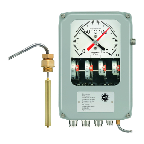
- Page 1 MESSKO BeTech ® POINTER THERMOMETER Operating Instructions BA 35 2716 1/02 EN...
- Page 2 BA 3527161/02 EN...
-
Page 3: Table Of Contents
Contents Contents Safety ....... . 4 Technical data ......13 Safety instructions . -
Page 4: Safety
Safety Product specification Safety CAUTION 1.1 Safety instructions Installation, electrical connection, commissioning, and maintenance of the device may only be carried All personnel involved in installation, commissioning, operation or maintenance of this equipment must: out by qualified, skilled personnel and only in ac- cordance with these operating instructions. - be suitably qualified and - strictly observe these operating instructions. -
Page 5: Tt Version (Option)
Installation (oil) and winding depends on the current in the winding. The secondary current of the transducer is proportional to the current in the winding. This transducer feeds a heating element inside the mechanical thermometer. That causes an increasing indication (gradient) of the measured oil temperature according to the transformer load. -
Page 6: Electrical Connection
Electrical connection Electrical connection This analogue output is an optional feature to the MESSKO BeTech Oil and Winding Temperature ® WARNING Indicators. The output is linear and proportional to the indicated temperature on the instrument dial, where Electrical voltages, danger to life! 4 mA is provided at the lowest value on the dial and All connecting wiring must be free of voltage before 20 mA at the highest value, for instance 4 mA at 0 °C... -
Page 7: Analog Output 4 - 20 Ma Current Loop Signal And 0 - 5 V Dc Voltage Output
A separate shielded cable is recommended for the wir- ing to the 4 - 20 mA analogue output. This includes the Supply Voltage and the mA output signal (= terminals 61, 62 and 63). No other signals should be wired through the same cable and make sure the shield is connected to ground on one side only. -
Page 8: Analog Output 0 - 5 V Dc Voltage Output
4.4 Analog output 0 - 5 V DC Voltage output The electrical wiring is easily connected to the terminal (see also chapter 8.4 for installation examples) board inside the OTI or WTI (see appendix, chapter 8.4). This analogue output is an optional feature to the MESSKO BeTech Oil and Winding Temperature ®... -
Page 9: Analog Output Pt100 Ohm Resistance Signal
4.5 Analog output Pt100 Ohm resistance signal remotely - no differences because of settings etc. as if (see also chapter 8.5 for installation examples) separate transmitters are used. This analogue output is an optional feature to the The electrical wiring is easily connected to the terminal MESSKO BeTech Oil and Winding Temperature board inside the OTI or WTI - (see appendix, chapter... -
Page 10: Switch Settings
Calibration 4.6 Switch settings The switches are individually adjustable and can be set to any temperature on the individual scale, regardless of other switch settings. The setting is done in the fol- lowing steps: a. Loosen the set screw on the orange pointer b. -
Page 11: Adjustment Of The Gradient
Adjustment of the gradient Adjustment of the gradient for Winding C) Technical data Temperature Indicator WTI Max heating current, I = 2.3 A continously Max heating current, I = 10 A for 5 seconds 6.1 Adjustment via heating current Thermal time constant: 9 minutes A) Gradient The gradients are shown for oil temperature 60°C The gradient is the temperature rise above oil tempe-... -
Page 12: Adjustment Via Built-In Matching Resistance Mrb110-1 Or Mrb110-2
6.2 Adjustment via built-in Matching Resistance MRB110-1 or MRB110-2 G) To verify the setting, please feed a stable current A) Determine the required gradient in °C (or K) (from (AC or DC) equivalent to the 100% CT current to the heat-run tests). the terminals 5 – 5, keep the instrument cover on B) Check the current (in Amps) from the CT at 100% the instrument and wait 45 minutes before verifying load. -
Page 13: Technical Data
Technical data Technical data Dimensions Refer to chap. 8.1 Materials Housing: Die casted aluminium, polyester powder coated, RAL 7033 Viewing glass: Laminated safety glass (standard); UV stabilized polycarbonate (optional) Capillary tube: Square flange 4 holes; G3/4“; G1“; 7/8“-14UNF; other thread joints on request Cable glands: Up to 3 x M20 x 1.5 and 1 x M16 for analogue output... -
Page 14: Appendix
Appendix 8.1 Dimensions 7.48" MESSKO ® BeTech M6x16 Wicklungstemperatur Winding temperature Température de l’enroulement Temperatura del devanado Temperature do enrolamento Temperatura avvolgimento Sarğı Sıcaklığı 绕组温度计 Lindningstemperatur 3.94" 7.65" Fig. 9 BA 3527161/02 EN... -
Page 15: Analogue Output / 4 - 20 Ma Current Loop Signal
8.2 Analogue Output / 4 - 20 mA Current Loop Signal (optional) Installation Example A: MESSKO ® BeTech RIA130-1 SNT36 mA +V D1272AT – – 4-20 mA 24 V DC Installation Example B: (SNT36 next to OTI/WTI and remote indicator MESSKO ®... -
Page 16: Analogue Output / 4 - 20 Ma Current Loop Signal And 0 - 5 V Dc Voltage Output
8.3 Analogue Output / 4 - 20 mA Current Loop Signal and 0 - 5 V DC Voltage output (optional) Installation Example A: MESSKO ® BeTech SCADA or RIA130-1 SNT36 mA +V V out computer D1272AT – – – V DC out 24 V DC 4-20 mA Installation Example B:... -
Page 17: Analogue Output / 0 - 5 V Dc Voltage Output
8.4 Analogue Output / 0 - 5 V DC Voltage output (optional) Installation Example A: MESSKO ® BeTech SCADA or SNT36 computer –V V out – – V DC out 24 V DC Installation Example B: (SNT36 next to OTI/WTI and SCADA/computer further away) MESSKO ®... -
Page 18: Analogue Output / Pt100 Ohm Restistance
MESSKO® TS 14 Analogue Output BeTech/Bellow Technology Pt 100 Ohm resistance signal 8.5 Analogue Output / Pt100 Ohm restistance signal (optional) Doc no. TS 14 Date. 2013-01-25 Rev. Page: 2 (2) Installation Example: Installation Example: MESSKO ® BeTech Pt 100 RIA130-1 RIA130-1 Pt 100... -
Page 19: Wiring Diagram / Oti 5 Switches And Wti 5 Switches And Wti 4 Switches + Mrb110
MESSKO® Wiring diagram OTI 4 switch and BeTech/Bellow Technology WTI 4 switch and WTI 4 switch + MRB110 8.6 Wiring diagram / OTI 5 switches and WTI 5 switches and WTI 4 switches + MRB110 (optional) Doc no. TS 40 Date. -
Page 20: Connection Terminals
8.7 Connection terminals MESSKO ® BeTech Matching resistance Fig. 15 BA 3527161/02 EN... -
Page 21: Dimensions Bulb No. 1
8.8 Dimensions bulb no. 1 □ 32,5 □ Ø 9,5 HEX 28 Fig. 16 8.9 Dimensions bulb no. 2 32,5 Ø 35 HEX 28 HEX 32 Fig. 17 8.10 Dimensions bulb no. 2F 35,5 Fig. 18 BA 3527161/02 EN... -
Page 22: Dimensions Bulb No. 6
8.11 Dimensions bulb no. 5 24,5 Ø 40 HEX 28 HEX 36 Fig. 19 8.12 Dimensions bulb no. 6 Fig. 20 8.13 Dimensions bulb no. 8 Fig. 21 BA 3527161/02 EN... -
Page 23: Dimensions Bulb No. 9
8.14 Dimensions bulb no. 9 24,5 Ø 40 HEX 28 HEX 36 Fig. 22 8.15 Dimensions bulb no. 10 32,5 Ø 35 HEX 28 HEX 32 Fig. 23 8.16 Dimensions bulb no. 27 31,5 Ø 40 HEX 28 HEX 36 Fig. - Page 24 Messko GmbH Gewerbegebiet An den Drei Hasen Messko-Platz 1, 61440 Oberursel, Germany Phone: +49 6171 6398-0 Fax: +49 6171 6398-98 E-Mail: messko-info@reinhausen.com www.reinhausen.com/messko Please note: The data in our publications may differ from the data of the devices delivered. We reserve the right to make changes without notice.
Need help?
Do you have a question about the MESSKO BeTech and is the answer not in the manual?
Questions and answers