Table of Contents
Advertisement
Quick Links
Advertisement
Table of Contents

Related Manuals for MR MESSKO MTO


Summary of Contents for MR MESSKO MTO
- Page 1 Oil level indicator ® MESSKO Operating instructions 5972470/03 EN...
- Page 2 © All rights reserved by Maschinenfabrik Reinhausen Dissemination and reproduction of this document and use and disclosure of its content are strictly prohibited unless expressly permitted. Infringements will result in liability for compensation. All rights reserved in the event of the granting of patents, utility models or designs. The product may have been altered since this document was published.
-
Page 3: Table Of Contents
Table of contents Introduction................ 7 Manufacturer.................. 7 Completeness.................. 7 Safekeeping.................. 7 Notation conventions ............... 7 1.4.1 Hazard communication system .............. 7 1.4.2 Information system.................. 8 1.4.3 Instruction system .................. 9 1.4.4 Typographic conventions ................ 9 Security ................ 11 Intended use .................. 11 Fundamental Safety Instructions ........... - Page 4 Table of contents Markings .................. 27 Transportation, receipt and handling of shipments...... 27 Storage of shipments.............. 29 Further transport ................ 29 Mounting ................ 30 Preparation .................. 31 6.1.1 Electromagnetic compatibility.............. 31 6.1.2 Safeguarding the power circuits.............. 33 6.1.3 Cable recommendation ................ 34 6.1.4 Checking the flanges..................
- Page 5 Table of contents Fault elimination .............. 81 General malfunctions (type TT) ............. 82 General malfunctions (types TTM and TTMR) ...... 83 Malfunctions of the 4...20 mA current loop ........ 83 Modbus communication malfunctions (types TTM and TTMR) .. 85 Relay box malfunctions (type TTMR) .......... 86 Self-diagnostic device status (types TTM and TTMR)....
- Page 6 Table of contents 12.6 9150605_000................ 116 12.7 9150921_000................ 117 12.8 9151305_000................ 118 12.9 7036358_000................ 119 12.10 7036293_000................ 120 12.11 6771687_000................ 121 12.12 6771692_000................ 122 12.13 6771696_000................ 123 Glossary ................ 124 5972470/03 EN...
-
Page 7: Introduction
Germany Tel.: +49 941 4090-0 E-mail: sales@reinhausen.com Internet: www.reinhausen.com MR Reinhausen customer portal: https://portal.reinhausen.com Further information on the product and copies of this technical file are avail- able from this address if required. 1.2 Completeness This technical file is incomplete without the supporting documents. -
Page 8: Information System
1 Introduction 1.4.1.1 Warning relating to section Warnings relating to sections refer to entire chapters or sections, sub-sec- tions or several paragraphs within this technical document. Warnings relat- ing to sections have the following format: WARNING Type of danger! Source of the danger and its consequences. ►... -
Page 9: Instruction System
1 Introduction Important information. 1.4.3 Instruction system This technical file contains single-step and multi-step instructions. Single-step instructions Instructions which consist of only a single process step are structured as fol- lows: Aim of action ü Requirements (optional). ► Step 1 of 1. ð... - Page 10 1 Introduction Typographic convention Purpose Example …>…>… Menu paths Parameter > Control pa- rameter Italics System messages, error Function monitoring alarm messages, signals triggered [► Number of pages] Cross reference [► Page 41]. Glossary entry, abbrevia- Dotted underscore Glossary entry ..............
-
Page 11: Security
2 Security ▪ Read this technical file through carefully to familiarize yourself with the product. ▪ This technical file is a part of the product. ▪ Read and observe the safety instructions provided in this chapter in partic- ular. ▪ Observe the warnings in this technical file to avoid function-related dan- gers. -
Page 12: Personal Protective Equipment
2 Security Personal protective equipment Loosely worn or unsuitable clothing increases the danger of becoming trapped or caught up in rotating parts and the danger of getting caught on protruding parts. This results in danger to life and limb. ▪ All necessary devices and personal protective equipment required for the specific task, such as a hard hat, safety footwear, etc. - Page 13 2 Security Safety markings Warning signs and safety information plates are safety markings on the product. They are an important aspect of the safety concept. Safety mark- ings are depicted and described in the chapter "Product description". ▪ Observe all safety markings on the product. ▪...
- Page 14 2 Security 2.3 Personnel qualification The person responsible for assembly, commissioning, operation and inspec- tion must have the following qualifications. Electrically skilled person The electrically skilled person has a technical qualification and therefore has the required knowledge and experience, and is also conversant with the ap- plicable standards and regulations.
- Page 15 2 Security 2.4 Personal protective equipment Personal protective equipment must be worn during work to minimize risks to health. ▪ Always wear the personal protective equipment required for the job at hand. ▪ Never wear damaged personal protective equipment. ▪ Observe information about personal protective equipment provided in the work area.
-
Page 16: Security
3 IT security Observe the following recommendations to operate the product safely: ▪ Ensure that only authorized personnel have access to the device. ▪ Ensure that the device is only operated by trained personnel who are fa- miliar with IT security. ▪... -
Page 17: Product Description
4 Product description This chapter contains an overview of the design and function of the product. 4.1 Scope of delivery The product is packaged with protection against moisture and is delivered as follows: ▪ Oil level indicator ▪ Float gauge with float rod (packed separately if longer than 400 mm, oth- erwise included in the MTO packaging) ▪... - Page 18 4 Product description Depending on the version, the measured value can be signaled via: ▪ Micro-switches ▪ Passive 4…20 mA analog output (TT) ▪ Active 4…20 mA analog output (TTM; 24 VDC device power supply re- quired) ▪ Modbus RTU RS485 interface (TTM; 24 VDC device power supply re- quired) ▪...
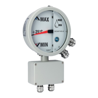
- Page 19 4 Product description Figure 1: MTO functional overview 1 Oil level indicator on the oil conser- 2 Oil level indicator vator 3 Electric switching signals (micro- 4 Version with two cable glands switches; optional) 5 Relay box (optional) 6 Electronic display 7 SCADA 5972470/03 EN...
-
Page 20: Design
4 Product description 4.3 Design Depending on the order, the oil level indicator has either one or two cable glands, one NPT cable gland, one ANSI socket or one MIL socket. Standard version with cable gland As an option, the M25x1.5 cable gland is also available in other versions, such as WADI (water-tight) or offshore. - Page 21 4 Product description Version with 1/2" NPT cable gland Figure 3: NPT cable gland, with locking cap as a transport lock Version with sockets Figure 4: ANSI socket (left); MIL socket (right) Ventilation The oil level indicator has a pressure equalization element for preventing the build-up of condensation in the device interior.
-
Page 22: Versions
4 Product description 4.4 Versions The oil level indicator can be equipped as follows: ▪ Without micro-switch ▪ With permanently set micro-switches – A maximum of 3 micro-switches are permanently mounted – Permanently set micro-switches are secured at the factory and cannot be subsequently adjusted. - Page 23 4 Product description Design Mounting posi- Micro-switches Float tion movement MTO-STF160V Inclined Maximum 3, permanently Radial MTO-STF160VTT 2)3) MTO-STF160VTTM 2)3)4) MTO-STF160VTTMR MTO-ST160G Vertical or in- Maximum 3, adjustable Axial clined MTO-ST160GTT 2)3) MTO-ST160GTTM 2)3)4) MTO-ST160GTTMR MTO-ST160GRM MTO-ST160GRMTT 2)3) MTO-ST160GRMTTM MTO-ST160- 2)3)4) GRMTTMR MTO-STF160G...
-
Page 24: Radial Float Movement
4 Product description 4.4.1 Radial float movement The oil level indicators with float movement in the radial direction can be mounted on straight and angled flanges. Inclining the oil level indicator makes it easier to read off the indicated values. Figure 6: Installation with angle of inclination α... -
Page 25: Safety Markings
4 Product description The float movement is transferred to the display part via gearing in the trans- mitter part in the ratio 1:1, 1:2, 1:3 or 1:4. Figure 7: Axial float movement with breathing sack 1 Display part 2 Transmitter part 3 Oil conservator 4 Float rod 5 Float gauge (1, 2, or 4 rollers) -
Page 26: Nameplate
4 Product description 4.6 Nameplate Figure 9: Nameplate 5972470/03 EN... -
Page 27: Packaging, Transport And Storage
5 Packaging, transport and storage 5.1 Purpose The packaging is designed to protect the packaged product during transport, loading, unloading and during periods of storage in such a way that no detri- mental changes occur. The packaging must protect the goods against per- mitted transport stresses such as vibration, knocks and moisture (rain, snow, condensation). - Page 28 5 Packaging, transport and storage Every delivered shipment must be checked for the following by the recipient before acceptance (acknowledgment of receipt): ▪ Completeness based on the delivery slip ▪ External damage of any type. The checks must take place after unloading when the cartons or transport container can be accessed from all sides.
-
Page 29: Storage Of Shipments
5 Packaging, transport and storage 5.5 Storage of shipments When selecting and setting up the storage location, ensure the following: ▪ Store the product and accessories in the original packaging until installa- tion. ▪ Protect stored goods against moisture (rain, flooding, water from melting snow and ice), dirt, pests such as rats, mice, termites etc. -
Page 30: Mounting
6 Mounting This chapter describes the installation and electrical connection of the oil level indicator. DANGER Electric shock! Danger of death due to electrical voltage when assembling/ disassembling the device. ► Switch off transformer on high-voltage side and low-voltage side. ►... -
Page 31: Preparation
6 Mounting Figure 10: Identical serial numbers (example) on the nameplate of the gauge part and on the transmitter part NOTICE Indication deviation Attaching transmitter parts and gauge parts together that have different se- rial numbers can have a detrimental effect on the stated tolerances of the fill level indication. - Page 32 6 Mounting 6.1.1.1 Wiring requirement of installation site Note the following when selecting the installation site: ▪ The system's overvoltage protection must be effective. ▪ The system's ground connection must comply with all technical regula- tions. ▪ Separate system parts must be joined by a potential equalization. 6.1.1.2 Wiring requirement of operating site Note the following when wiring the operating site: ▪...
-
Page 33: Safeguarding The Power Circuits
6 Mounting 6.1.2 Safeguarding the power circuits You may only connect the device to circuits with an external overcurrent pro- tective device and an all-pole isolating device so that the equipment can be fully de-energized if required. Suitable equipment includes isolating devices in accordance with IEC 60947-1 and IEC 60947-3 (e.g. -
Page 34: Cable Recommendation
6 Mounting 6.1.3 Cable recommendation Please note the following recommendation from the manufacturer when wiring the device: ▪ If both low voltage and extra-low voltage are connected in the device, it must be ensured that the circuits for extra-low voltage and for low voltage in the connection area and in the cable are separated from each other with double insulation. -
Page 35: Checking The Flanges
6 Mounting Modbus A shielded twisted-pair cable is recommended. For reasons of space, it may be advantageous to run the Modbus and the 24 V supply in the same cable. Connect the shield to the Modbus master (e.g. in the control cabinet). Route the shield to the device without interruption and use an EMC cable gland on the device to connect the shield. - Page 36 6 Mounting Figure 12: Checking the counter-flange for evenness and gaps Flange requirements ▪ Flanges on the oil conservator – Flush and even – Evenness deviation ≤ 0.2 mm ▪ Sealing surface of the flanges on the oil conservator – Clean and undamaged –...
-
Page 37: Gasket Requirements
6 Mounting 6.1.5 Gasket requirements Observe the following information when selecting the gaskets: ▪ Ensure that the gasket and sealing groove meet the latest technical stan- dards. ▪ Use new and clean gaskets. ▪ Use O-rings or flat gaskets. ▪ Never use paper gaskets. ▪... -
Page 38: Standard Flange
6 Mounting 4. Ensure that the device is mounted vertically. Figure 13: Mounting position 5. Mount the connection flange with connection holes or stud bolts for ac- commodating the device. When doing so, comply with the hole dimen- sions and hole distances in accordance with the type of flange connection, see: ▪... -
Page 39: Rm Flange (Mto-St160Rm)
6 Mounting Figure 14: Connecting flange with holes for accommodating the MTO standard flange 1 Version 1: 4 blind holes with inter- 2 Version 2: 4 stud bolts with thread nal thread max. M12 [0.47"] max. M12 [0.47"] 3 Version 3: 4 through-holes 4 Length of the bolts beyond the de- Ø 13 mm [0.51"] for bolt-nut con- vice flange or total height of the... - Page 40 6 Mounting 2. Affix a connecting flange with the following parameters to the oil conserva- tor via this through hole: ▪ Through hole with an internal diameter of 66 mm [2.60"] ▪ 4 bolt connections with a bolt circle of 101.6 mm [4.0"] as one of the fol- lowing versions: Figure 15: Connecting flange with holes for accommodating the RM flange 1 Version 1: 4 blind holes with inter-...
-
Page 41: Nat/Ds Flange (Mto-St160Rm)
6 Mounting 6.2.3 NAT/DS flange (MTO-ST160RM) NOTICE! Only RM float gauges with brass float rods up to 350 mm [13.78"] long may be used with this flange version. In order to be able to connect the device with an NAT/DS flange, establish the following connection conditions on the oil conservator depending on the space available: 1. - Page 42 6 Mounting Figure 16: Connecting flange with holes for accommodating the NAT/DS flange 1 Version 1: 4 blind holes with inter- 2 Version 2: 4 stud bolts with thread nal thread max. M8 [5/16" or max. M8 [5/16" or 5/16" ‑ 18 UNC 5/16" ‑ 18 UNC or 1/16" ‑ 27 NPT] or 1/16" ‑ 27 NPT] 3 Version 3: 4 through-holes 4 Length of the bolts beyond the de-...
-
Page 43: Mounting The Mto On The Oil Conservator
6 Mounting 6.3 Mounting the MTO on the oil conservator NOTICE Damage to the transformer! Improperly tightening the bolts will lead to a high dispersion of the preload forces and can lead to the required surface pressure of the gasket not be- ing reached or to the permissible surface pressure on the MTO flange be- ing exceeded (leakage, material breakage). - Page 44 6 Mounting 2. Loosen the 4 screws on the rear housing edge so that the display part and transmitter part can be separated from each other. Place both parts sepa- rately on a firm and clean surface. Figure 17: Separating the display part and transmitter part 5972470/03 EN...
- Page 45 6 Mounting 3. Insert the float rod into the shaft hole for the magnetic coupling up to the stop. Figure 18: Inserting the float rod 1 Shaft for magnetic coupling 2 Transmitter part 3 Display part 4 Fixing screw 5 Float rod 6 Lock nut 7 Clamping screw for the float gauge 4.
- Page 46 6 Mounting NOTICE! Damage to the oil level indicator! The oil level indicator may be- come damaged if the transmitter part is incorrectly mounted or if the incor- rect gaskets are used. Observe the sections "Checking the flanges" [►Section 6.1.4, Page 35] and "Gasket requirements" [►Section 6.1.5, Page 37].
- Page 47 6 Mounting 11. Depending on the method of attachment, tighten the 4 screws or nuts crosswise with 30% of the target tightening torque. Observe the total height of the connecting elements when using washers and locking ele- ments or sealing rings (see appendices [►Section 12, Page 110]) on the MTO flange.
- Page 48 6 Mounting 16. Place the display part on the transmitter part so that the recesses in the housing lie over the 4 fixing screws. ð The magnetic coupling engages. Figure 22: Placing the display part on the transmitter part 17. Push the display part firmly onto the transmitter part and tighten the 4 screws on the rear housing edge crosswise.
-
Page 49: Mounting An Mto With Axial Float Rod
6 Mounting 6.3.2 Mounting an MTO with axial float rod The stop plates on the lower side for MIN and on the upper side for MAX are preset in production depending on the dial. The stop plates can be moved and adjusted by slightly loosen- ing the screw for this purpose and then tightening it again. - Page 50 6 Mounting 2. Insert the float rod into the hole in the float shaft for the magnetic coupling. When doing so, observe the direction of the rotation lock at the end of the float rod and push the float rod to the stop in the elongated hole in the gearing axle.
- Page 51 6 Mounting 3. Tighten the clamping screw firmly and secure with the lock nut. Figure 26: Securing the float rod 4. Screw the transmitter part with the "TOP" marking upwards. NOTICE! Damage to the oil level indicator! The oil level indicator may be- come damaged if the transmitter part is incorrectly mounted or if the incor- rect gaskets are used.
- Page 52 6 Mounting 8. Insert the entire float gauge into the oil conservator. (Depending on the design of the oil conservator and the mounting position of the MTO, it may be necessary to mount the float rod after mounting the transmitter part; see Special instructions [►Section 6.3.3, Page 54].) Figure 27: Inserting the float rod 9.
- Page 53 6 Mounting 14. Only if a flat gasket is being used, tighten all of the screws again cross- wise with the maximum target tightening torque until the screws cannot be turned any further at the maximum tightening torque. Figure 28: Mounting the transmitter part with gasket (example) NOTICE! Clean up the contact areas of the magnetic coupling in the gauge part and transmitter part of metal cuttings and dirt particles.
-
Page 54: Mounting The Mto On An Inclined Flange
6 Mounting 17. Push the gauge part firmly onto the transmitter part and tighten the 4 screws on the rear housing edge crosswise. Figure 30: Fastening the gauge part on the transmitter part 6.3.3 Mounting the MTO on an inclined flange If the mounting situation does not allow for the transmitter part to be inserted with the float gauge fully installed, note the following special instructions: ü... - Page 55 6 Mounting When mounting inside the oil conservator, observe the following conditions: 1. Align the float rod so that the float buoy(s) float horizontally in the insulat- ing fluid. Figure 31: Aligning the float buoys horizontally 2. Mount the collection grille for the breathing sack so that the float gauge can move freely at all oil conservator fill levels.
-
Page 56: Electrical Connection
6 Mounting 6.4 Electrical connection DANGER Electric shock! Danger of death due to electrical voltage when assembling/ disassembling the device. ► Switch off transformer on high-voltage side and low-voltage side. ► Lock transformer to prevent unintentional restart. ► Make sure that everything is de-energized. ►... -
Page 57: Connecting Mto With Cable Screw Connection / Npt Cable Screw Connection
6 Mounting 6.4.1 Connecting MTO with cable screw connection / NPT cable screw connection To connect the oil level indicator with cable screw connection, open the de- vice, insert the prepared cable and secure the screw connection. 6.4.1.1 Connecting the interfaces (optional) NOTICE Damage to the device! Applying an incorrect test voltage to the terminals for the 4…20 mA analog... - Page 58 6 Mounting 3. Use ferrules for flexible lines (with a collar of max. 0.75 mm²). Figure 32: Cable preparation for interfaces You will need an actuating tool if wires have to be released from the Push-in terminals used. An actuating tool is not absolutely necessary for connecting the wires.
- Page 59 6 Mounting 3. Release the actuator. Figure 33: Connecting the analog output 4. Connect an evaluation unit with driving output (18...30 VDC) or, if neces- sary, an additional power supply (24 VDC). 6.4.1.1.2 Connecting the active 4…20 mA analog output (TTM version) The device is equipped with an active current output that converts the oil level into an electrical 4...20 mA signal.
- Page 60 6 Mounting 3. Release the actuator. Figure 34: Connecting the supply voltage Connecting the 4...20 mA analog output in accordance with the connection diagram 1. Press in the white actuator using the actuating tool (width 2.5 mm). 2. Connect the wires to the terminals "4…20 mA (+/-)". Do so by pushing the wires through the opening up to the stop.
- Page 61 6 Mounting 4. Connect an evaluation unit without a driving input. 6.4.1.1.3 Connecting Modbus (TTM and TTMR versions) The device is equipped with a Modbus RTU (RS-485) interface that digitally transmits the oil level. The interface has a half-duplex design. Preparation 1.
- Page 62 6 Mounting 3. Release the actuator. Figure 37: Connecting Modbus The circuit board provides the possibility to loop through the RS485 connection to the next device (daisy-chain) via the sec- ond terminal strip. If the device is the only bus device or the last bus device, in- sert a terminating resistor (120 Ω, 0.5 W) into the second ter- minal strip between "A"...
- Page 63 6 Mounting 6.4.1.2 Removing the bayonet seal ring Before connecting, setting or testing the oil level indicator, the bayonet seal ring must be removed. ► Turn the bayonet seal ring approx. 30...40° counter-clockwise and then lift out together with the viewing glass. The viewing glass is held in place by a rubber gasket.
- Page 64 6 Mounting 6.4.1.3 Opening the cover plate The micro-switches are connected as shown in the diagram printed on the inside of the cover plate. 1. Open the cover plate. Figure 39: Opening the cover plate 2. To prevent tension on the cable glands and to comply with the bending radii of the cables used, secure cables after a maximum of one meter.
- Page 65 6 Mounting Metal locking screws are available as accessories. 1. Remove the locking screw on the adapter, unscrew the cable gland and remove the dust protection disk. Figure 40: Opening the locking screw and removing the dust protection disk 1 Standard cable gland 2 WADI cable gland (water-tight) 3 Offshore cable gland (stainless steel) 5972470/03 EN...
- Page 66 6 Mounting 2. Lead the connection cable through the cable gland and adapter and tighten the cable gland. Figure 41: Mounting the cable gland (example) 6.4.1.4.1 EMC double cable gland (accessory) Use shielded conductors for the Modbus wiring and connect the shield on both sides (same shielding potential for all devices).
- Page 67 6 Mounting 2. Insulate the braid at the lower end with insulating tape. Figure 42: Stripping and insulating the cables The cable gland can now be attached. To do so: 1. Gently twist the cables and feed through the openings in the cable gland. Figure 43: Inserting the cables 2.
- Page 68 6 Mounting 3. Mark this position above the gland on the cable sheath. Figure 44: Marking the cables 4. Pull the cables back out to a length of 10 mm from the marking. Figure 45: Pulling the cables out 5. Attach the cable gland to the device housing (wrench size 30). 6.
- Page 69 6 Mounting Unitronic Robust C (TP) 3 x 2 x 0.5 from Lapp ▪ Shielded; 3x twisted pair (TP); 0.5 mm – 1 TP used for 24 VDC – 1 TP used for Modbus A and B – 1 TP used for Modbus_Common_GND ▪ External diameter 8.7 mm 6.4.1.5 Mounting the NPT screw connection NOTICE! If the NPT cable screw connection is not used, remove the locking cap and replace it with an NPT dummy plug in order to ensure the...
- Page 70 6 Mounting 6.4.1.6 Connecting to ground To ground the device, proceed as follows: ► Secure the protective conductor (PE) with cable shoe or ferrule to the grounding screw of the oil level indicator. Figure 47: Grounding the device 6.4.1.7 Connecting the micro-switches WARNING Electric shock! The micro-switches may be connected either to only extra-low-...
- Page 71 6 Mounting Limited space in the device can make the connection more dif- ficult. Connect the data lines before the micro-switches. Route the micro-switches through the lower cable gland and 4… 20 mA / 24 V DC / Modbus through the upper cable gland. Prepare the following before connecting the cable: 1.
- Page 72 6 Mounting 2. Close the cover plate. Figure 49: Closing the cover plate 6.4.1.9 Positioning and closing the bayonet seal ring NOTICE! If the rubber gasket and glass do not seal all the way around, liq- uids or moisture can penetrate and damage the device. ►...
-
Page 73: Connecting The Mto With Connector
6 Mounting 6.4.2 Connecting the MTO with connector The oil level indicator is pre-wired and set. The micro-switches are con- nected as shown in the diagram printed on the inside of the cover plate. All that is necessary is to connect the protective conductor and the connection cable. - Page 74 6 Mounting 3. Observe the connection diagram and connect the wires at the free end of the connection cable in the control cabinet. 4. Close the cover plate and the bayonet seal ring. 5. Connect the socket connection cable to the device. NOTICE! Damage to cables and lines! When plugging the socket con- nection cable into the socket, the cable can become rotated, leading to...
-
Page 75: Mto With Relay Box (Optional)
6 Mounting 6.4.3 MTO with relay box (optional) The relay box has four relays. The switching thresholds (dependent on the oil level) can be set individually via Modbus. The switching symbols in the re- lay box indicate the de-energized state (LED off). Figure 53: Relay box structure 1 Normally closed contacts 2 Coil... - Page 76 6 Mounting The cable glands on the relay box are used only to connect the relay. No cables may be routed to the device. The relays are deactivated in the default settings. They can be configured via Modbus; to do so, see chapter Commissioning –...
-
Page 77: Commissioning
7 Commissioning 7.1 Transporting in the installed state If transportation of the entire assembled unit is necessary between mounting the device onto the transformer / oil conservator and commissioning it, please also refer to the information on further transport [►Section 5.6, Page 29]. -
Page 78: Configuring Modbus
7 Commissioning You can check if the main switching contacts are working correctly by per- forming a sink test: 1. Adjust the fill level of the oil conservator to the mark of the filling tempera- ture and check. 2. Continue filling the oil conservator to the MAX mark and check. 3. - Page 79 7 Commissioning Setting the Modbus address The following values are available for the Modbus address: Modbus address MTO delivery status Maximum value Minimum value Issuing the same network address twice will lead to malfunc- tions. Parity For data transmission, the parity is determined as follows: Parity Fixed specification Even...
-
Page 80: Maintenance, Inspection And Care
8 Maintenance, inspection and care Maintenance The device is maintenance-free. Inspection Depending on the conditions of use of the device and the national regula- tions in the respective country of use, the transformer manufacturers can specify different inspection intervals. ► Observe the inspection intervals defined in CIGRE Publication No. 445 "Guide for Transformer Maintenance"... -
Page 81: Fault Elimination
9 Fault elimination This chapter describes how to eliminate operating faults. If a solution cannot be found for a fault, contact Maschinenfabrik Reinhausen GmbH: Maschinenfabrik Reinhausen GmbH MR Service & Complaint Falkensteinstrasse 8 93059 Regensburg Germany E-mail: service@reinhausen.com E-mail: complaint@reinhausen.com Please have the following data at hand: ▪... -
Page 82: General Malfunctions (Type Tt)
9 Fault elimination ▪ When did the error first occur? Is there a correlation with events such as lightning surge testing (transformer station), thunderstorms, transformer disconnection/reconnection after short circuit or ground fault...? ▪ Is the error constant or sporadic? Is it correlated with other events/condi- tions, such as extreme ambient temperatures? ▪... -
Page 83: General Malfunctions (Types Ttm And Ttmr)
9 Fault elimination 9.2 General malfunctions (types TTM and TTMR) You are using a Modbus and an active 4...20 mA current loop serial inter- face. Characteristics/ Cause Remedy details No function Power supply not present ▪ Check cables (4...20 mA) ▪ Check power supply (18… 30 VDC) No function (Mod- bus) - Page 84 9 Fault elimination Characteristics/ Cause Remedy details The receiver mea- ▪ A part of the current is run- ▪ Loop in multimeter and sures a 20 mA ning through a parallel path measure loop current that is ▪ Load resistance too high ▪...
-
Page 85: Modbus Communication Malfunctions (Types Ttm And Ttmr)
9 Fault elimination 9.4 Modbus communication malfunctions (types TTM and TTMR) Characteristics/ Cause Remedy details No communication Power supply not present ▪ Check cables possible (continu- ▪ Check device supply (18… ous) 30 VDC) ▪ RS485 lines A, B not con- Info: A = D0 = D+;... -
Page 86: Relay Box Malfunctions (Type Ttmr)
9 Fault elimination 9.5 Relay box malfunctions (type TTMR) Characteristics/ Cause Remedy details Relay does not ▪ Power supply not present ▪ Check cables shut on/off and ▪ Device defective ▪ Check device supply (18… Modbus and/or 30 VDC) 20 mA is not work- Relay does not ▪... -
Page 87: Self-Diagnostic Device Status (Types Ttm And Ttmr)
9 Fault elimination 9.6 Self-diagnostic device status (types TTM and TTMR) The device checks its own functionality cyclically (self-diagnostic). In Modbus input register 0 (data type: UINT16), the device reports a corre- sponding status via status bits. Multiple bits can also be set at the same time. - Page 88 9 Fault elimination Status bit value/char- Cause Remedy acteristic/detail 4: Pointer out of mea- ▪ Device defective ▪ Contact Maschinenfabrik suring range: Pointer Reinhausen GmbH. ▪ Extremely low oil angle is 20 angular de- level ▪ Is the oil level really extremely grees smaller than the low or high? Compare the re- ▪...
-
Page 89: Disposal
10 Disposal Observe the national disposal regulations in the country of use. 10.1 SVHC information in accordance with the REACH regulation This product complies with the provisions of European Regulation 1907/2006/EC dated December 18, 2006 on the Registration, Evaluation, Authorization and Restriction of Chemicals (REACH). The following components of the product contain >... -
Page 90: Technical Data
11 Technical data 11.1 Ambient conditions Permissible ambient conditions Location of use Indoors and outdoors, tropic-proof Operating tempera- -40...+80 °C ture Storage tempera- -50...+80 °C ture Ambient air tempera- -40...+80 °C* ture Relative humidity Fog-free up to 80% Ventilation Pressure equalization element in the indicator for the preven- tion of water condensation Installation altitude Up to 2,000 m above mean sea level... -
Page 91: Electrical Connection
11 Technical data 11.2 Electrical connection 11.2.1 Micro-switches Micro-switches Freely adjustable Permanently set (version F) Quantity 1…3 1…3 Only adjustable at the fac- tory Display area Depending on device configuration; Standard; MAX... +20 °C...MIN Switch points Depending on device configuration; Standard; 5° before MIN, 5°... - Page 92 11 Technical data Utilization category for freely adjustable micro-switch Utilization cate- Typical application Rating/nominal gory in accor- operation dance with IEC 60947‑5‑1 AC-12 Regulation of resistive load and semi-con- 230 V ductor load resistance with disconnection (50/60 Hz) via optocoupler AC-15 Regulation of electromagnetic load resis- 230 V 0.26 A tance with AC voltage...
-
Page 93: Ma Outputs
11 Technical data Switching capacity for permanently set micro-switch Micro-switch version Switching capacity Permanently set 250 V AC 15 A, cos φ = 1 With MIL plug: 13 A, cos φ = 1 250 VDC 0.25 A with resistive load 12 VDC 5 A with resistive load Extended ranges on request. 11.2.2 4…20 mA outputs 4…20 mA output (type TT) Feed-in voltage of the passive 18…30 VDC unregulated, max. -
Page 94: Rs485 Interface (Types Ttm And Ttmr)
11 Technical data 11.2.3 RS485 interface (types TTM and TTMR) RS485 interface Supply voltage 24 VDC unregulated, max. 10% residual ripple, pro- tected against polarity reversal Max. current consumption 40 mA without relay 80 mA with four active relays Standard EIA/TIA-485 Wiring 2-wire; half-duplex Terminal designation Polarity: A = D+;... -
Page 95: Modbus Rtu
11 Technical data 11.2.5 Modbus RTU Factory settings Modbus address Baud rate Parity 19200 EVEN Input register Function code "04" to read the information Validity of the measured value stored in the INPUT register addresses 1…3: It can be seen via the DISC register with address 4 (Boolean) whether the measured value is invalid (0) or valid (1). - Page 96 11 Technical data Function code "03" to read the information Function code "06/16" to write the information Register Data type Designation Setting option UINT16 Modbus address 1…247 UINT16 Modbus baud rate 0: 4800 1: 9600 2: 19200 3: 38400 4: 57600 5: 19200 UINT16 Modbus parity...
- Page 97 11 Technical data We recommend deactivating the 4...20 mA analog output when it is not needed. This will prevent the pseudo-error "4...20 mA output defective". This will also reduce the power loss in the device and extend its service life. Cannot be overwritten by the customer Float parameters are saved in big-endian word order.
-
Page 98: Connection Options
11 Technical data 11.2.6 Connection options Standard cable gland M25x1.5 nickel-plated brass Clamping range 9...20 mm Figure 54: Standard cable gland 1 Gland base 2 Pressure ring 3 Universal sealing ring, NBR 4 Pressure ring 5 Dust protection disk 6 Pressure screw 5972470/03 EN... - Page 99 11 Technical data WADI cable screw connection (water-tight; optional) Figure 55: WADI cable screw connection; material: nickel-plated brass; clamping range 13...20 mm Offshore cable screw connection (optional) Figure 56: Offshore cable screw connection; material: stainless steel (V4A); clamping range 9...17 mm 5972470/03 EN...
- Page 100 11 Technical data EMC double cable gland (optional) Figure 57: EMC double cable gland 5972470/03 EN...
- Page 101 11 Technical data 1/2" NPT screw connection (optional) Figure 58: Connecting joint for NPT screw connection; material: nickel-plated brass ANSI plug (optional) Connecting cable with ANSI socket not included in the scope of delivery; can be or- dered separately Figure 59: ANSI plug on the device (left); Connecting cable with ANSI socket (right) Color Terminal Color...
-
Page 102: Dimensions And Weight
11 Technical data Figure 60: Terminal strip assignment 11.3 Dimensions and weight MESSKO® MTO Housing of the gauge Ø 173 mm [Ø 6.81″]; height 213 mm [8.39″]; depth 81 mm part [3.19″] Height with MESSKO® TT30 (optional): 322 mm [12.68″] Weight 3.7 kg With relay box (optional): 4.4 kg Please refer to the Appendices [►Section 12, Page 110] for further specifi- cation and details on the MTO versions. -
Page 103: Dimensions (Axial Float Movement)
11 Technical data For an example with NPT gland and an inclination of α = 45°, refer to the drawing in the appendix. 11.3.2 Dimensions (axial float movement) For the MESSKO® MTO-ST160 with axial float movement, refer to the draw- ing in the appendix. 11.3.3 Float gauge The values specified may vary depending on the configuration of the oil level indicator. - Page 104 11 Technical data 11.3.3.2 Float gauge for axial float movement Design Projection A Straight: Standard 69 mm or 268 mm Max. 350 mm 5972470/03 EN...
- Page 105 11 Technical data Float gauge versions The float gauge design depends on the layout of the oil conservator: Mounting position Breathing Float gauge design sack Upright: Without ▪ 1 rolling float gauge (L ≤ 1,000 mm) Upright: With ▪ 2 rolling float gauges (L ≤...
- Page 106 11 Technical data 11.3.3.3 Installation positions for axial MTO MTO axial, option 1 without breathing sack Figure 61: Option 1 without breathing sack, with associated float gauge A Projection SL Float gauge length for dimension- H Installed height, depending on float L = SL + 1/2 diameter of the float buoy gauge length 5972470/03 EN...
- Page 107 11 Technical data MTO axial, option 2 and 3, with breathing sack Figure 62: Option 2 with upright installation; Option 3 with angled installation; float gauge see also option 4 A Projection SL Float gauge length for dimension- H Installed height, depending on * Breathing sack mounting position 5972470/03 EN...
- Page 108 11 Technical data MTO axial, option 4, with breathing sack and float gauge Figure 63: Option 4 with installation angled from below; float gauge for options 2, 3, 4 A Projection SL Float gauge length for dimension- H Installed height, depending on * Breathing sack mounting position 5972470/03 EN...
- Page 109 11 Technical data 11.3.3.4 Further types of float gauges Figure 64: Types of float gauges 1 RM float gauge (rod: brass) MTO- For radial and axial ST160RM 2 Cubic float gauge (rod: alu- MTO-ST160 For radial minum) 3 Cylindrical float gauge (rod: alu- MTO-ST160 For radial angled design minum)
-
Page 110: Appendix
12 Appendix 5972470/03 EN... - Page 112 3.19" max. 0.79" Ausladung / DISTANCE TUBE LENGTH 0.33" 0.79" 1.10" 1.77" 4.72" 1: 5 Druckausgleichselement / PRESSURE COMPENSATION ELEMENT Kabelverschraubung Modbus / CABLE GLAND MODBUS Kabelverschraubung Schalter / CABLE GLAND SWITCH Relais Box / RELAIS BOX TRANSFORMER ACCESSORIES SERIAL NUMBER DIMENSION ...
- Page 114 A = Ausladung / DISTANCE TUBE LENGTH 1.77" 0.31" 4.72" Maße / DIMENSIONS Neigung / INCLINATION Neigung / INCLINATION Neigung / INCLINATION mm / [IN] α = 15° α = 30° α = 45° 150 +1 150+1 274 +1 [5.91" +.04"] [5.91"...
- Page 115 3.19" 0.79" Ausladung / DISTANCE TUBE LENGTH 0.157" 0.79" 1.77" 1.10" 4.72" 1.77" 1: 5 Ansicht / VIEW Z Druckausgleichselement / PRESSURE COMPENSATION ELEMENT Kabelverschraubung Modbus / CABLE GLAND MODBUS Steckeranschluss ANSI od. Westinghouse / CONNECTION ANSI OR. WESTINGHOUSE Relais Box / RELAIS BOX Anschluss Masseausgleich / COONECTION MASS BALANCING TRANSFORMER ACCESSORIES ...
- Page 116 3.19" max. 0.79" Ausladung DISTANCE TUBE LENGTH 0.33" 0.79" 1.10" 1.77" 4.72" 1: 5 Druckausgleichselement / PRESSURE COMPENSATION ELEMENT Kabelverschraubung Modbus / CABLE GLAND MODBUS Steckeranschluss ANSI od. Westinghouse / CONNECTION ANSI OR. WESTINGHOUSE Relais Box / RELAIS BOX Anschluss Masseausgleich / COONECTION MASS BALANCING TRANSFORMER ACCESSORIES ...
- Page 117 3.19" 0.79" Ausladung / DISTANCE TUBE LENGTH 0.33" 0.16" 0.79" 1.77" 1.10" 4.72" 1.77" 1: 5 Ansicht / VIEW Z Druckausgleichselement / PRESSURE COMPENSATION ELEMENT Kabelverschraubung Modbus / CABLE GLAND MODBUS Steckeranschluss Mil. od. M / CONNECTION MIL. OR. M Relais Box / RELAIS BOX Anschluss Masseausgleich / COONECTION MASS BALANCING TRANSFORMER ACCESSORIES ...
- Page 118 3.19" 0.79" Ausladung / DISTANCE TUBE LENGTH 0.33" 0.79" 1.77" 1.10" 4.72" 1: 5 Druckausgleichselement / PRESSURE COMPENSATION ELEMENT Kabelverschraubung Modbus / CABLE GLAND MODBUS Steckeranschluss MIL. od. M / CONNECTION MIL. OR. M Relais Box / RELAIS BOX Anschluss Masseausgleich / COONECTION MASS BALANCING TRANSFORMER ACCESSORIES ...
- Page 119 5: 1 ( O 4) 5: 1 Fläche Verdrehsicherung AREA ROTATION LOCK Aluminium / ALUMINUM ROTATION LOCK 1 ROLLER FLOAT Serialnummer Maßangaben in mm, soweit OIL LEVEL INDICATOR MTO-ST160G(TT) Materialnummer Blatt nicht anders AXIAL DESIGN 101266900M angegeben...
- Page 120 5: 1 4,05 5: 1 Fläche Verdrehsicherung AREA ROTATION LOCK Al-Rohr / AL-PIPE Al-Rohr / AL-PIPE ROTATION LOCK 2 AND 4 ROLLER FLOAT Serialnummer Maßangaben in mm, soweit OLI LEVEL INDICATOR MTO-ST160G(TT) Materialnummer Blatt nicht anders AXIAL DESIGN 101266890M angegeben...
- Page 121 O 13 .512" O 102 4.016" O 134 5.264" .335" 4x Dichtungsscheibe / GASKET M12 Material / MATERIAL: EN AW - 1200 (Al99) ; H14 ; 32 ... 45 HB ANSI H35.1 (M)-1200 ; H14 ; 32 ... 45 HB GB/T 3190-1200 ;...
- Page 122 Schnitt A-A O 101,6 O 134 5.276" 4.000" .335" O 11,2 .441" 3,05 .120" 4x Dichtungsscheibe / GASKET M10 Material / MATERIAL: EN AW - 1200 (Al99) ; H14 ; 32 ... 45 HB ANSI H35.1 (M)-1200 ; H14 ; 32 ... 45 HB GB/T 3190-1200 ;...
- Page 123 Schnitt A-A O 8,73 O 79,38 O 134 5.276" .344" 3.125" .335" 1,59 .063" 4x Dichtungsscheibe / GASKET M8 Material / MATERIAL: EN AW - 1200 (Al99) ; H14 ; 32 ... 45 HB ANSI H35.1 (M)-1200 ; H14 ; 32 ... 45 HB GB/T 3190-1200 ;...
- Page 124 Glossary Ambient air temperature Operating temperature Permissible temperature of the air in the Permissible temperature in the immedi- surroundings of the equipment in opera- ate surroundings of the device during tion on which the device is installed. operation taking ambient influences, for example due to the equipment and in- stallation location, into consideration.
- Page 126 Maschinenfabrik Reinhausen GmbH Falkensteinstrasse 8 93059 Regensburg +49 (0)941 4090-0 sales@reinhausen.com www.reinhausen.com ® 5972470/03 EN - MESSKO MTO - F0365903 - 06/23 - Maschinenfabrik Reinhausen GmbH 2023 THE POWER BEHIND POWER.
Need help?
Do you have a question about the MESSKO MTO and is the answer not in the manual?
Questions and answers