Sign In
Upload
Download
Table of Contents
Contents
Add to my manuals
Delete from my manuals
Share
URL of this page:
HTML Link:
Bookmark this page
Add
Manual will be automatically added to "My Manuals"
Print this page
×
Bookmark added
×
Added to my manuals
Manuals
Brands
MR Manuals
Measuring Instruments
MSENSE DGA 2
Operating instructions manual
MR MSENSE DGA 2 Operating Instructions Manual
Online oil analysis
Hide thumbs
1
2
Table Of Contents
3
4
5
6
7
8
9
10
11
12
13
14
15
16
17
18
19
20
21
22
23
24
25
26
27
28
29
30
31
32
33
34
35
36
37
38
39
40
41
42
43
44
45
46
47
48
49
50
51
52
53
54
55
56
57
58
59
60
61
62
63
64
65
66
67
68
69
70
71
72
73
74
75
76
77
78
79
80
81
82
83
84
85
86
87
88
89
90
91
92
93
94
95
96
97
98
99
100
101
102
103
104
page
of
104
Go
/
104
Contents
Table of Contents
Bookmarks
Table of Contents
Table of Contents
Introduction
Manufacturer
Subject to Change Without Notice
Completeness
Safekeeping
Notation Conventions
Hazard Communication System
Information System
Instruction System
Typographic Conventions
Safety
Appropriate Use
Fundamental Safety Instructions
Personnel Qualification
Personal Protective Equipment
Security
Product Description
Scope of Delivery
Function Description
Design
Safety Markings and Nameplate
Packaging, Transport and Storage
Purpose
Suitability, Structure and Production
Markings
Transportation, Receipt and Handling of Shipments
Storage of Shipments
Further Transport
Installation
Installation Recommendation
Mounting the Device
Preparing the Transformer and Ball Valve
Mounting the MSENSE® DGA 2/3
Electrical Connection
Electromagnetic Compatibility
Cable Recommendation
Routing and Preparing the Cables
Supply Voltage and Protective Conductor
Device Grounding
Analog Outputs
Main Switching Contacts
SCADA Connection
Ensuring Offshore Capability
Commissioning
Service Interface
Installing the MESSKO® MSET Parameterization Software
Commissioning in Existing Systems
Parameterization
Settings for Carbon Monoxide (DGA 3 Only), Hydrogen and H2O Concentrations in the Oil
General Settings
Modbus Settings
Operation
Operating the Device with Display
General Operation
Main Screen / Operating Display
Events
Operating the Device Without Display
Fault Elimination
Messages Regarding the Safety Switching Contact
Other Faults
Replace Safety Fuse
Maintenance
Inspection
Maintenance
Oil Extraction
Device Field Calibration
Taking a Sample for Field Calibration
Field Calibration
Reading out the Service Database
Cleaning
Removal
Removing the MSENSE® DGA 2/3
Disposal
Technical Data
Appendix
Device Dimensions with 285 MM Measuring Pipe Length
Device Dimensions with 507 MM Measuring Pipe Length
Connecting Flange Dimensions
Electrical Connection
Data Point Table for Modbus RTU
Spare Parts List
Advertisement
Quick Links
1
Table of Contents
2
Installation
3
Scada Connection
Download this manual
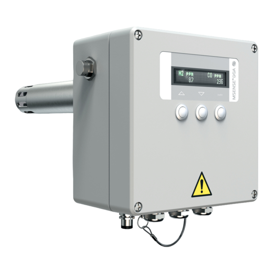
Online Oil Analysis
®
MSENSE
DGA 2/3
Operating Instructions
BA4001150/10 EN
Table of
Contents
Previous
Page
Next
Page
1
2
3
4
5
Advertisement
Table of Contents
Need help?
Do you have a question about the MSENSE DGA 2 and is the answer not in the manual?
Ask a question
Questions and answers
Related Manuals for MR MSENSE DGA 2
Measuring Instruments MR MSENSE DGA 9 Installation And Operating Instructions Manual
(143 pages)
Measuring Instruments MR MSENSE DGA 3 Operating Instructions Manual
Online oil analysis (104 pages)
Measuring Instruments MR MSENSE DGA 2/3 Operating Instructions Manual
(104 pages)
Measuring Instruments MR MSENSE BM Operating Instructions Manual
Monitoring system (190 pages)
Measuring Instruments MR ETOS IM Operating Instructions Manual
(412 pages)
Measuring Instruments MR MESSKO MTO Operating Instructions Manual
Oil level indicator (126 pages)
Measuring Instruments MR TAPGUARD 260 Quick Reference Manual
(23 pages)
Measuring Instruments MR MSENSE BM Operating Instructions Manual
Monitoring system (250 pages)
Measuring Instruments MR MESSKO BeTech Operating Instructions Manual
Pointer thermometer (24 pages)
Measuring Instruments MR TAPCON LV Operating Instructions Manual
Voltage monitoring (118 pages)
Measuring Instruments MR MESSKO MMK Operating Instructions Manual
Oil level indicator (40 pages)
Measuring Instruments MR YD-200 User Manual
Urine analyzer (27 pages)
Measuring Instruments MR MESSKO PQ96 Operating Instructions Manual
Moving coil meter (8 pages)
Measuring Instruments MR MESSKO MFLOC 2.0 Operating Instructions Manual
Flow indicator (44 pages)
Measuring Instruments MR MESSKO EI100 Operating Instructions Manual
Electronic remote display (60 pages)
This manual is also suitable for:
Msense dga 3
Table of Contents
Print
Rename the bookmark
Delete bookmark?
Delete from my manuals?
Login
Sign In
OR
Sign in with Facebook
Sign in with Google
Upload manual
Upload from disk
Upload from URL


Need help?
Do you have a question about the MSENSE DGA 2 and is the answer not in the manual?
Questions and answers