Table of Contents
Advertisement
Quick Links
Advertisement
Table of Contents

Related Manuals for MR MSENSE DGA 2/3


Summary of Contents for MR MSENSE DGA 2/3
- Page 1 Online oil analysis ® MSENSE DGA 2/3 Operating instructions 4001150/12 EN...
- Page 2 © All rights reserved by Maschinenfabrik Reinhausen Dissemination and reproduction of this document and use and disclosure of its content are strictly prohibited unless expressly permitted. Infringements will result in liability for compensation. All rights reserved in the event of the granting of patents, utility models or designs.
-
Page 3: Table Of Contents
Table of contents Table of contents Introduction......................... 6 Manufacturer............................ 6 Subject to change without notice ...................... 6 Completeness............................. 6 Safekeeping............................ 6 Notation conventions .......................... 6 1.5.1 Hazard communication system .......................... 7 1.5.2 Information system.............................. 7 1.5.3 Instruction system .............................. 8 1.5.4 Typographic conventions ............................ 8 Security .......................... - Page 4 Table of contents Mounting the device.......................... 24 6.2.1 Preparing the transformer and ball valve ...................... 25 6.2.2 Mounting the MSENSE® DGA 2/3........................ 29 Electrical connection......................... 38 6.3.1 Electromagnetic compatibility.......................... 39 6.3.2 Cable recommendation ............................ 39 6.3.3 Routing and preparing the cables ........................ 39 6.3.4 Supply voltage and protective conductor ...................... 40 6.3.5 Device grounding .............................. 41 6.3.6...
- Page 5 Table of contents 10.3 Oil extraction............................. 69 10.4 Device field calibration........................ 70 10.4.1 Taking a sample for field calibration........................ 70 10.4.2 Field calibration .............................. 72 10.4.3 Reading out the service database........................ 78 10.5 Cleaning............................ 80 Removal.......................... 81 11.1 Removing the MSENSE® DGA 2/3 .................... 81 Disposal..........................
-
Page 6: Introduction
Germany Tel.: +49 941 4090-0 E-mail: sales@reinhausen.com Internet: www.reinhausen.com MR Reinhausen customer portal: https://portal.reinhausen.com Further information on the product and copies of this technical file are avail- able from this address if required. 1.2 Subject to change without notice The information contained in this technical file comprises the technical speci- fications approved at the time of printing. -
Page 7: Hazard Communication System
1 Introduction 1.5.1 Hazard communication system Warnings in this technical file are displayed as follows. 1.5.1.1 Warning relating to section Warnings relating to sections refer to entire chapters or sections, sub-sec- tions or several paragraphs within this technical document. Warnings relat- ing to sections have the following format: Type of danger! WARNING... -
Page 8: Instruction System
1 Introduction 1.5.3 Instruction system This technical file contains single-step and multi-step instructions. Single-step instructions Instructions which consist of only a single process step are structured as fol- lows: Aim of action ü Requirements (optional). ► Step 1 of 1. ð... -
Page 9: Security
2 Security 2 Security ▪ Read this technical file through carefully to familiarize yourself with the product. ▪ This technical file is a part of the product. ▪ Read and observe the safety instructions provided in this chapter in partic- ular. - Page 10 2 Security Personal protective equipment Loosely worn or unsuitable clothing increases the danger of becoming trapped or caught up in rotating parts and the danger of getting caught on protruding parts. This results in danger to life and limb. ▪ All necessary devices and personal protective equipment required for the specific task, such as a hard hat, safety footwear, etc.
-
Page 11: Personnel Qualification
2 Security Modifications and conversions Unauthorized or inappropriate changes to the product may lead to personal injury, material damage and operational faults. ▪ Only modify the product after consultation with Maschinenfabrik Rein- hausen GmbH. Spare parts Spare parts not approved by Maschinenfabrik Reinhausen GmbH may lead to physical injury, damage to the product and malfunctions. -
Page 12: Personal Protective Equipment
If maintenance is not carried out by our Technical Service department, please ensure that the personnel who carry out the mainte- nance are trained and authorized to do so by Maschinenfabrik Reinhausen GmbH. MR Service & Complaint Maschinenfabrik Reinhausen GmbH Falkensteinstrasse 8 93059 Regensburg Germany service@reinhausen.com... - Page 13 2 Security Hearing protection To protect against hearing damage. Protective gloves To protect against mechanical, thermal and electrical hazards. Table 3: Personal protective equipment ® Maschinenfabrik Reinhausen GmbH 2023 4001150/12 EN MSENSE DGA 2/3...
-
Page 14: Security
3 IT security 3 IT security Observe the following recommendations to operate the product safely. ▪ Ensure that only authorized personnel have access to the device. ▪ Only use the device within an ESP (electronic security perimeter). ▪ Ensure that the device is only operated by trained personnel who are fa- miliar with IT security. -
Page 15: Product Description
4 Product description 4 Product description The detection of dissolved gases in transformer oil is generally considered to be the first indication of emerging faults in transformers. Several interna- tional standards highlight the relevance of this examination method, includ- ing the IEEE Std C57.104™-2008, IEC 60422, IEC 60567 and IEC 60599 standards. -
Page 16: Scope Of Delivery
4 Product description The device is available in two device versions: Measured variables Hydrogen (H2) Carbon Moisture Oil tempera- monoxide (H2O) ture (CO) MSENSE® DGA 2 MSENSE® DGA 3 MSENSE® DGA 2 for measuring and analyzing the fault gas hydrogen (H2) present in the transformer oil, for detecting the oil moisture content and for measuring the oil temperature. -
Page 17: Function Description
4 Product description 4.2 Function description The MSENSE® DGA 2/3 measuring head is positioned in the transformer in- sulating oil. There is often a large distance between the measuring head and the origin of the gases. It is therefore important for the early detection of gases that the oil at the installation position is in motion, either due to natural convection or due to artificially generated oil circulation. -
Page 18: Design/Versions
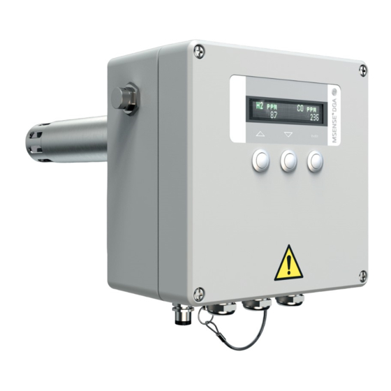
4 Product description 4.3 Design/versions Figure 1: MSENSE® DGA 2/3 DGA 2 Measurement components H DGA 3 Measurement components H moisture in oil and oil tempera- CO, moisture in oil and oil tem- ture (for mineral oils) perature (for mineral oils) 1 Ventilation 2 Housing cover screw connection 3 Ball valve locking lever... -
Page 19: Safety Markings And Nameplate
4 Product description Additional signal protocols DNP 3.0; (with additional protocol converter) Modbus TCP; IEC 61850-8-1 MMS (optional) Accessories (optional) Power supply unit for protocol con- verter Offshore version Offshore 4.4 Safety markings and nameplate The following safety markings are used on the product: Figure 2: Safety markings and nameplate Description Warning sign "Do not close!"... -
Page 20: Packaging, Transport And Storage
5 Packaging, transport and storage 5 Packaging, transport and storage 5.1 Purpose The packaging is designed to protect the packaged product during transport, loading, unloading and during periods of storage in such a way that no detri- mental changes occur. The packaging must protect the goods against per- mitted transport stresses such as vibration, knocks and moisture (rain, snow, condensation). - Page 21 5 Packaging, transport and storage Every delivered shipment must be checked for the following by the recipient before acceptance (acknowledgment of receipt): ▪ Completeness based on the delivery slip ▪ External damage of any type. The checks must take place after unloading when the cartons or transport container can be accessed from all sides.
-
Page 22: Storage Of Shipments
5 Packaging, transport and storage 5.5 Storage of shipments When selecting and setting up the storage location, ensure the following: ▪ Store the product and accessories in the original packaging until installa- tion. ▪ Protect stored goods against moisture (rain, flooding, water from melting snow and ice), dirt, pests such as rats, mice, termites etc. -
Page 23: Mounting
6 Mounting 6 Mounting This chapter describes how to correctly mount and connect the device. DANGER Electric shock! Risk of fatal injury due to electrical voltage. Always observe the following safety regulations when working in or on electrical equipment. ► Disconnect the equipment. ►... -
Page 24: Mounting The Device
6 Mounting Less recommended installation positions On the side in the lower area; so long as oil circulation is ensured at the in- tended position, installing the device here may be considered. Connection pipe from the transformer tank to the cooling system: the oil tem- peratures here can be very high and influence the quality of the measure- ments Impermissible installation positions... -
Page 25: Preparing The Transformer And Ball Valve
6 Mounting 6.2.1 Preparing the transformer and ball valve ü A flange is mounted on the transformer that matches the device ball valve flange. 1. Carefully remove the ball valve from the packaging and protect it against damage. 2. Remove the fixing screw from the dummy plug. Figure 5: Unchaining the dummy plug 3. - Page 26 6 Mounting 4. Pulling the dummy plug out Figure 7: Pulling the dummy plug out Package the dummy plug and store safely in case the device is to be re- moved at a later date. 5. Turn the ball valve lever to the "closed" position. Figure 8: Closing the ball valve Missing or incorrectly positioned round gasket NOTICE...
- Page 27 6 Mounting 6. Lubricate the two round gaskets at the front of the ball valve. Figure 9: Lubricating the ball valve gaskets 7. Lubricate the two round gaskets at the rear of the ball valve. Figure 10: Lubricating the ball valve gaskets NOTICE! Mounting errors can lead to non-tight seals and thus uncon- trolled oil leakage.
- Page 28 6 Mounting 9. Mount the closed ball valve on the transformer and align via the elongated holes so that the locking lever is at the top. Use fastening materials made of stainless steel A4 in the strength category -70. Figure 11: Mounting the closed ball valve Flange Screws DN50 PN6...
-
Page 29: Mounting The Msense® Dga 2/3
6 Mounting 6.2.2 Mounting the MSENSE® DGA 2/3 1. Remove the device from the packaging and place it securely on a scratch- resistant and non-slip level surface. Figure 12: Setting the device down securely When doing so, ensure that the display of the device version with display is not damaged. - Page 30 6 Mounting Store the protective cap in case the device is to be removed at a later date. 3. Open the connection for taking oil samples. To do so, push the bayonet connector toward the device, hold down and pull the sealing plug out. Re- lease the bayonet connector.
- Page 31 6 Mounting NOTICE! Make sure the oil extraction adapter belongs to this device. If the standard version and the offshore version are mixed up, the oil extrac- tion connection and the adapter can become damaged. Push the supplied oil extraction adapter into the opening until it audibly snaps into place. Figure 15: Connecting the oil extraction adapter 5.
- Page 32 6 Mounting NOTICE Risk of damage The device measuring pipe can become tilted when it is inserted into the ball valve. ► Support the weight of the device by hand and push the pipe into the ball valve with even pressure up to the stop (tangible resistance). Figure 17: Inserting the device into the ball valve 7.
- Page 33 6 Mounting Risk of burns CAUTION Hot oil can push the device out of the ball valve and spray out. ► Ensure that the safety chain is correctly bolted in place and does not sag. 8. Position a collecting tray below the valve opening in the oil extraction adapter and open the ball valve by aligning the lever up to the stop paral- lel to the measuring pipe.
- Page 34 6 Mounting 11. Close the oil extraction adapter valve. Figure 20: Closing the oil extraction adapter 12. Remove the adapter from the device. To do so, push the bayonet con- nector toward the device, hold down and pull the adapter out. Release the bayonet connector.
- Page 35 6 Mounting 13. Put the sealing plug back on the bayonet connector for venting and tak- ing oil samples and push it in until it snaps into place. Figure 22: Inserting the sealing plug Ensure that the connection is tightly sealed. 14.
- Page 36 6 Mounting Electric shock WARNING Risk of fatal injury due to electrical voltage. ► Maintain the necessary distance from the active part of the transformer (see Device dimensions with 285 mm measuring pipe length [►Section 14.1, Page 93] and Device dimensions with 507 mm measuring pipe length [►Section 14.2, Page 94]).
- Page 37 6 Mounting 16. Reduce the length of the sagging safety chain by inserting the supplied chain connector through two links in the chain and closing it. Figure 25: Locking the safety chain Alternatively, a padlock can be used to secure the device against unautho- rized removal.
-
Page 38: Electrical Connection
6 Mounting 6.3 Electrical connection This chapter describes the correct electrical connection of the device. WARNING Electric shock Risk of fatal injury due to electrical voltage. ► De-energize the device and system peripherals and take measures to en- sure that they cannot be switched back on. Only connect the device to circuits with an external overcurrent protection device and an all-pole isolating device so that the equipment can be fully de- energized if required (for service, maintenance, etc.). -
Page 39: Electromagnetic Compatibility
6 Mounting 6.3.1 Electromagnetic compatibility The device has been developed in accordance with applicable EMC stan- dards. The following points must be observed in order to maintain the EMC standards. ▪ The system's overvoltage protection must be effective. ▪ The system's ground connection must comply with all technical regula- tions. -
Page 40: Supply Voltage And Protective Conductor
6 Mounting To prepare the cable correctly, proceed as follows: 1. Open the device connection area. To do so, unscrew the 4 captive screws on the housing cover. The cover is connected to the device via hinges and can be flipped open. 2. -
Page 41: Device Grounding
6 Mounting Ensure that the protective conductor cross-section is at least the same as all other connection conductors. 6.3.5 Device grounding Connect the ground connection on the device ball valve to the transformer ground connection. Figure 29: Ground connection With offshore devices, the grounding point of the ball valve is to be greased (see chapter Ensuring offshore capability [►Section 6.4, Page 47]). - Page 42 6 Mounting The terminal strip is assigned by default (factory setting) as follows: Figure 30: Analog outputs ▪ CO concentration: terminals 4, 5, 6 (MSENSE® DGA 3 only) ▪ H2 concentration: terminals 7, 8, 9 ▪ RH relative humidity: terminals 10, 11, 12 To connect the cables, proceed as follows: 1.
-
Page 43: Main Switching Contacts
6 Mounting 6.3.7 Main switching contacts The device has 5 floating main switching contacts: S1, S2, S3, S4 and one safety switching contact = fail-safe relay (FSR) for status signaling. These contacts are designed as change-over contacts and are connected to the terminals 13/14/15 (S1), 16/17/18 (S2), 19/20/21 (S3), 22/23/24 (S4) and 25/26/27 (FSR). -
Page 44: Scada Connection
6 Mounting To connect the system periphery cables to the main switching contacts, pro- ceed as follows: ü Only use specified cables. Note the cable recommendation. 1. Connect the leads that are to be wired to the device in accordance with the illustration of the main switching contacts. - Page 45 6 Mounting Device address: 1 to 247 Baud rate: 4800, 9600, ...115200 Parity: even Detailed information is available in the MESSKO® MSET parameterization software operating instructions. 6.3.8.3 Modbus RTU protocol The data point table for the Modbus RTU protocol is available in the Appen- dix [►Section 14.5, Page 98].
- Page 46 6 Mounting 6.3.8.5 Integration of the device into a 2-conductor system Figure 34: 2-conductor system *) When integrating the device into a 2-conductor system, the following con- ductors are to be bridged in the external supply line: ▪ Conductors TXD0 (pin 1) and RXD0 (pin 4) ▪...
-
Page 47: Ensuring Offshore Capability
6 Mounting 6.4 Ensuring offshore capability To prevent corrosion in offshore applications, greasing the following points is recommended (tube of grease included in delivery): 1. Cover the housing cover screws with grease. Time period: After opening the housing cover; at least every 2 years. Figure 35: Greasing the housing cover screws ®... - Page 48 6 Mounting 2. Fill the holes in the housing base with grease. Time period: At least every 2 years. Figure 36: Holes in the housing base 3. Apply grease to the ball valve steel clamping ring liberally. Avoid greasing the interior of the ball valve. Time period: After each mounting or removal process;...
- Page 49 6 Mounting Figure 38: Grounding point on the ball valve ® Maschinenfabrik Reinhausen GmbH 2023 4001150/12 EN MSENSE DGA 2/3...
-
Page 50: Commissioning
7 Commissioning 7 Commissioning NOTICE Damage to the device! Damage to the electronics of the device due to incorrect supply voltage! ► Provide the correct supply voltage in accordance with the nameplate on an external isolating device. The device is ready for operation once it has been connected to the supply voltage and completed a run-in period of at least 24 hours. -
Page 51: Installing The Messko® Mset Parameterization Software
7.2 Installing the MESSKO® MSET parameterization software You can download the latest version of the MESSKO® MSET parameteriza- tion software from the MR Reinhausen customer portal. 1. Register for download in the customer portal: https://portal.reinhausen.com. 2. Create your ECOSENSE® ACTIVE PART under myEquipment > Com- ponents. -
Page 52: Commissioning In Existing Systems
7 Commissioning Detailed information on using the MESSKO® MSET parameterization soft- ware can be found in the corresponding operating instructions. 7.3 Commissioning in existing systems The manufacturer recommends a field calibration of the device parameters to ensure optimum operation, in particular with: ▪... -
Page 53: Settings For Carbon Monoxide (Dga 3 Only), Hydrogen And H2O Concentrations In The Oil
7 Commissioning ▪ UNIX time stamp ▪ Service code ▪ Action maintenance information ▪ Modbus baud rate ▪ Modbus address ▪ Service database ▪ Field calibration ▪ Default calibration 7.4.1 Settings for carbon monoxide (DGA 3 only), hydrogen and H2O concentrations in the oil The upper warning and alarm values for the carbon monoxide content (CO) (MSENSE® DGA 3 only), the hydrogen content (H2) and the H2O concen-... -
Page 54: General Settings
7 Commissioning Limit value Default*) Minimum Maximum Gas formation rate too high alarm 50 ppm/d 0 ppm/d 80 ppm/d 4 mA signal setting 15 ppm 15 ppm 1,999 ppm 20 mA signal setting 1,000 ppm 16 ppm 2,000 ppm Table 8: Hydrogen (H2) limit values *) Recommended values based on IEEE C57.104, Condition 1 Moisture (H2O) limit values Limit value Default... - Page 55 7 Commissioning Time stamp Make a note of the time stamp of the oil sample extraction for the laboratory. This is needed for the water content (H2O in ppm) calibration. The time stamp is updated with service code 1: sample extraction. Once the sample has been analyzed by a laboratory, the time stamp must be entered together with the analysis results for adjustment via the MESSKO®...
-
Page 56: Modbus Settings
7 Commissioning Maintenance information A maintenance message that is configurable can be issued by the device via the available relay contacts (refer to the MESSKO® MSET parameterization software). It is possible to have a maintenance message issued 6 months in advance and when maintenance is due. 7.4.3 Modbus settings You can configure the following settings for the Modbus communication us- ing the MESSKO®... -
Page 57: Operation
8 Operation 8 Operation Note the differences between the MSENSE® DGA 2 and MSENSE® DGA 3 device versions. Unless stated otherwise, the description refers to the MSENSE® DGA 3 device version. Device ver- Measured variables sion Hydrogen (H2) Carbon Moisture Oil tempera- monoxide (H2O) ture (CO) MSENSE®... -
Page 58: Operating The Device With Display
8 Operation 8.1 Operating the device with display The display and 3 operating keys can be used to call up and display the set- tings of the device. Use the MESSKO® MSET software included in the de- vice's scope of delivery for the parameterization. There are 3 menu levels: Menu level 1 Menu level 2... -
Page 59: General Operation
8 Operation 8.1.1 General operation 8.1.1.1 Menu level 1 = Display of the CO, H2 and moisture content and the oil temperature Action Reaction Press the ENTER key briefly Move forward one menu level 8.1.1.2 Menu level 2 = Setup selection Action Reaction Press UP key... -
Page 60: Main Screen / Operating Display
8 Operation 8.1.2 Main screen / operating display The following displays appear in rotation once the device has been commis- sioned: Figure 41: Display with current H2 and CO content Left-hand side Right-hand side CO (MSENSE® DGA 3 only) Hydrogen content in ppm Carbon monoxide content in ppm Figure 42: Display with current H2O content and oil temperature ®... - Page 61 8 Operation Left-hand side Right-hand side Water content (humidity) in %RH Oil temperature in °C The water content (humidity) display can be converted from %RH to ppm via the MESSKO® MSET parameterization software if required (service code 4 and 5). When the measured data is transmitted (e.g. to a SCADA control center or a laptop), the water content is always transmitted in both display formats.
-
Page 62: Events
8 Operation These limits and rates are suitable for initial commissioning. However, the systems (transformer and device) must be aligned with each other over time. Thus, with sufficient data, the limits / formation rates for the "warning" and "alarm" values should be able to be calculated and loaded via the MESSKO® MSET parameterization software. - Page 63 8 Operation The following table lists the possible events and the respective recom- mended actions: Event Text display Recommended action CO concentration warning CO Warn. (DGA 3 only) CO concentration alarm CO Alarm (DGA 3 only) CO gas formation rate warning CO Formation Warn.
-
Page 64: Operating The Device Without Display
8 Operation 8.2 Operating the device without display Always use the MESSKO® MSET parameterization software for viewing the measured data and events, and for setting the parameters. ® MSENSE DGA 2/3 4001150/12 EN Maschinenfabrik Reinhausen GmbH 2023... -
Page 65: Fault Elimination
Message via FSR Cable break in the supply Check wiring; in the event line of doubt, contact MR Ser- vice & Complaint Drop in the supply voltage Check supply voltage; in the event of doubt, contact MR Service & Complaint... - Page 66 9 Fault elimination Electric shock WARNING Risk of fatal injury due to electrical voltage ► Only appropriately trained personnel may replace the fuse. ► Before opening the connection area in order to replace the fuse, the de- vice is to be disconnected from all voltage sources via the prescribed dis- connecting switch and secured against reconnection.
-
Page 67: Maintenance
10 Maintenance 10 Maintenance Inspection and maintenance are required for the operational safety and to maintain measurement accuracy. 10.1 Inspection Monitoring of the device is limited to occasional visual inspections and a reg- ular oil extraction. For efficiency reasons, these inspection tasks can be combined with the usual checks on the transformer. -
Page 68: Maintenance
Service Maintenance required Maintenance required Contact MR Technical Service In case of a maintenance signal, please contact the Technical Service of Maschinenfabrik Reinhausen GmbH (MR) immediately: Maschinenfabrik Reinhausen GmbH Technical Service Postfach 12 03 60 93025 Regensburg Germany Phone: +49 941 4090-0 E-mail: service@reinhausen.com... -
Page 69: Oil Extraction
10 Maintenance 10.3 Oil extraction Figure 45: Oil extraction The scope of delivery includes two MESSKO® sample extraction kits for tak- ing oil samples via the oil sample extraction connection. For information on taking oil samples, refer to the included instructions BA2938054 and chapter Device field calibration [►Section 10.4, Page 70] in these instructions. -
Page 70: Device Field Calibration
10 Maintenance 10.4 Device field calibration The field calibration of the device gas analysis values serves to ensure the correct measurement results: ▪ For aged insulating oils ▪ For modified oils (e.g., the addition of additives) ▪ For oils that do not satisfy the standards ASTM D3486-091, IEC 60296 or IEC 60422 A field calibration should be performed if the following conditions apply: Condition... - Page 71 10 Maintenance To take an oil sample, proceed as follows: 1. Complete the sample information sheet included in the oil extraction kit. When doing so, enter the current measured values under "MSENSE® DGA adjustment" for: – H2 – CO (MSENSE® DGA 3 only) –...
-
Page 72: Field Calibration
10 Maintenance 2. Take an oil sample in accordance with IEC 60567 and send it to the MESSKO® oil laboratory in suitable packaging. The sample analysis val- ues will be used later for the field calibration. Figure 47: MESSKO® sample extraction kit for extracting and shipping oil samples 10.4.2 Field calibration Once the sample has been analyzed in the oil laboratory, you will be sent the oil sample report for the oil analysis. - Page 73 10 Maintenance A specific recommendation for a field calibration can be found in the "Rec- ommendations" chapter. Figure 48: Sample report of the oil analysis (example) The individual analysis values can be found on the following pages of the analysis report: Figure 49: Analysis values (example) ®...
- Page 74 10 Maintenance To perform the field calibration, proceed as follows: 1. Connect the MSENSE® DGA 2/3 to the PC via the USB service adapter and open the MESSKO® MSET parameterization software. ð The parameterization software connects to the device. Figure 50: MSET main screen 2.
- Page 75 10 Maintenance 4. Select the gases for which you want a field calibration. Enter the labora- tory results as the reference corresponding to the respective gas. Figure 52: Field calibration step 1 5. Enter the date of the oil sample from the laboratory results. Figure 53: Entering the date ®...
- Page 76 10 Maintenance 6. Click on Start to initiate the field calibration. Figure 54: Starting the field calibration ð The process progress can be viewed in the status window. The process may take several minutes. 7. Wait until the status column shows whether or not the calibration is possi- ble.
- Page 77 9. Wait until the result of the calibration is displayed in the status column. Figure 57: Calibration successful 10. Upon successful calibration, you can close the window and disconnect the connection between the MSENSE DGA 2/3 and the laptop. 11. Unscrew the USB service adapter. ®...
-
Page 78: Reading Out The Service Database
2. Click on Service in the top right. 3. Click on the Create service database button and save the zip file to the laptop. Figure 58: Service database 4. Contact MR Technical Service and send the zip file. ® MSENSE DGA 2/3... - Page 79 10 Maintenance Maschinenfabrik Reinhausen GmbH Technical Service Postfach 12 03 60 93025 Regensburg Germany Phone: +49 94140 90-0 E-mail: service@reinhausen.com ® Maschinenfabrik Reinhausen GmbH 2023 4001150/12 EN MSENSE DGA 2/3...
-
Page 80: Cleaning
10 Maintenance 10.5 Cleaning When necessary, the installed device can be cleaned from the outside with water and a mild lye. Only use a dry cleaning cloth to wipe down the measuring head of the unin- stalled device (see chapter Design/versions [►Section 4.3, Page 18]). ®... -
Page 81: Removal
11 Removal 11 Removal CAUTION Hot oil escape Risk of injury and slipping. ► Wear safety clothing. ► Carry out the operating steps in the specified sequence. ► Ensure that the shutter valve remains closed after the removal of the de- vice. - Page 82 11 Removal 2. Release the ball valve clamp connection. Figure 60: Releasing the ball valve clamp connection 3. Pull the device as far as possible out of the ball valve. The chain should now be tightly tensioned. Danger of damaging the measuring pipe! NOTICE If the device is operated in front of a slide valve, the tightly tensioned chain ensures that the measuring pipe of the device has been pulled out far...
- Page 83 11 Removal 4. Close any upstream valves and slides. 5. Close the ball valve and position the oil collecting tray under the opening of the ball valve. Figure 62: Closing the ball valve Danger of crushing due to falling device CAUTION The device is now free.
- Page 84 11 Removal 6. Unscrew the fixing screw for the safety chain on the device far enough to free the chain. Pull the safety chain out and screw the fixing screw back into place. Figure 63: Releasing the link chain 7. Carefully pull the device out of the ball valve. NOTICE Type and source of danger Ensure that the device does not become jammed during this procedure.
- Page 85 11 Removal 8. Set the device down securely on a scratch-resistant and non-slip level surface. Figure 65: Setting the device down securely When doing so, ensure that the display of the device version with display is not damaged. 9. Place the supplied red protective cap onto the measuring pipe and close the protective cap opening with adhesive tape.
- Page 86 11 Removal 10. Clean the device with a dry cloth. The device has now been removed and can be transported or stored in suit- able packaging. The ball valve is then to be secured: Hot oil escape CAUTION Risk of injury and slipping. ►...
- Page 87 11 Removal 2. Close the air-vent valve and tighten the ball valve clamp connection. Figure 68: Tightening the ball valve clamp connection 3. Secure the free end of the safety chain with the dummy plug fixing screw. Attach the chain under as much tension as possible. Figure 69: Securing the dummy plug with link chain ®...
- Page 88 11 Removal 4. Remove the warning sign "Do not close!" on the slide valve. Figure 70: Slide valve warning sign ® MSENSE DGA 2/3 4001150/12 EN Maschinenfabrik Reinhausen GmbH 2023...
-
Page 89: Disposal
12 Disposal 12 Disposal Observe the national disposal regulations in the respective country of use. 12.1 SVHC information in accordance with the REACH regulation This product complies with the provisions of European Regulation 1907/2006/EC dated December 18, 2006 on the Registration, Evaluation, Authorization and Restriction of Chemicals (REACH). -
Page 90: Technical Data
13 Technical data 13 Technical data Measurement Application Determination of the gas concentration of fault gases as well as moisture in oil and oil temperature of mineral-based transformer insulating oil in accordance with IEC 60296:2012 / ASTM D3487-09 Measured vari- Humidity Oil temper- ables (only for ature... - Page 91 13 Technical data Please contact MR to check the use in case of extreme conditions At the point of measurement Device properties Mechanical connection Via ball valve and configurable flange DN50 or DN80 (several flanges available); with safety chain for safe in-...
- Page 92 Entry of the reference values in accordance with the lab- oratory report Service Reading out the internal device service database for fur- ther analysis by MR Service experts Please note that Microsoft has stopped providing regular support for ver- sions earlier than Windows 10. Mechanical tests Vibration 10–150 Hz with 2g, 2 h (IEC 60068-2-6)
-
Page 93: Appendix
14 Appendix 14 Appendix 14.1 Device dimensions with 285 mm measuring pipe length Figure 71: Device dimensions with 285 mm measuring pipe Flange, see table [►Section 14.3, Page 95] Minimum immersion depth Recommended immersion depth ® Maschinenfabrik Reinhausen GmbH 2023 4001150/12 EN MSENSE DGA 2/3... -
Page 94: Device Dimensions With 507 Mm Measuring Pipe Length
14 Appendix 14.2 Device dimensions with 507 mm measuring pipe length Figure 72: Device dimensions with 507 mm measuring pipe Flange, see table [►Section 14.3, Page 95] Minimum immersion depth Recommended immersion depth ® MSENSE DGA 2/3 4001150/12 EN Maschinenfabrik Reinhausen GmbH 2023... -
Page 95: Connecting Flange Dimensions
14 Appendix 14.3 Connecting flange dimensions Figure 73: Flange DN50 PN6; DN50 PN16 For o-ring gasket (included in delivery) For any gasket (gasket not included in delivery) Figure 74: Flange DN80 PN16 For o-ring gasket (included in delivery) For any gasket (gasket not included in delivery) ®... - Page 96 14 Appendix Flange dimensions table Flange version mm [inch] mm [inch] mm [inch] mm [inch] mm [inch] DN50 PN6 Ø140 [5.51″] Ø110 [4.33″] 70° 4 x 50° Ø13 [0.51″] Ø81 [3.19″] Ø65 [2.56″] DN50 PN16 Ø165 [6.50″] Ø125 [4.92″] 70° 4 x 50°...
-
Page 97: Electrical Connection
14 Appendix 14.4 Electrical connection Figure 76: Electrical connection Supply voltage (overvoltage category III) 95...280 V AC 50/60 Hz or 95...280 V DC (any polarity) Protective conductor 4-12 Analog outputs 4…20 mA passive (must be supplied with 24 V DC) 13-27 Main switching contacts (change-over contacts for state signaling): capacity: 30 V DC / 5 A to 300 V DC / 0.25 A or 250 V AC / 5 A;... -
Page 98: Data Point Table For Modbus Rtu
14 Appendix 14.5 Data point table for Modbus RTU Separate input register Address Size Description Designation 1 byte On / Off CO limit 1 1 byte On / Off CO limit 2 1 byte On / Off limit 1 1 byte On / Off limit 2 1 byte On / Off... - Page 99 14 Appendix Input register Address Size Description Designation (dec.) 4 bytes, None CO value ppm SFLOAT 4 bytes, None Value ppm SFLOAT 4 bytes, None O Value ppm SFLOAT 4 bytes, None Oil Temperature SFLOAT 4 bytes, Empty 2 SFLOAT 4 bytes, None O %RH SFLOAT 4 bytes, Empty 4 SFLOAT...
-
Page 100: Spare Parts List
14 Appendix 14.6 Spare parts list Seq. Art. No. Designation 1001099900 MSENSE® 2/3 oil extraction unit (standard) Sample extraction adapter (standard version) Material: stainless steel V2A and PTFE 1001100100 MSENSE® 2/3 oil extraction unit (offshore) Sample extraction adapter (offshore version) Material: stainless steel V4A and PTFE 1001100300 MSENSE®... - Page 101 14 Appendix Seq. Art. No. Designation 1001101000 MSENSE® 2/3 ball valve DN80 PN16/285 For measuring pipe length 285 mm Flange diameter: DN80 Pressure rating: PN16 Material: stainless steel V4A Including o-ring gasket, material: FPM (Viton) 1001101100 MSENSE® 2/3 ball valve DN80 PN16/507 For measuring pipe length 507 mm Flange diameter: DN80 Pressure rating: PN16...
-
Page 102: Glossary
Glossary Glossary Insulating fluid temperature Storage temperature Permissible temperature of the insulating fluid in Permissible temperature for storing the device in the product or directly on the product. an unmounted state or in a mounted state so long as the device is not in operation. Operating temperature Permissible temperature in the immediate sur- roundings of the device during operation taking... - Page 104 Maschinenfabrik Reinhausen GmbH Falkensteinstrasse 8 93059 Regensburg +49 (0)941 4090-0 sales@reinhausen.com www.reinhausen.com ® 4001150/12 EN - MSENSE DGA 2/3 - 1000590112 - 02/23 - Maschinenfabrik Reinhausen GmbH 2023 THE POWER BEHIND POWER.
Need help?
Do you have a question about the MSENSE DGA 2/3 and is the answer not in the manual?
Questions and answers