Table of Contents
Advertisement
Quick Links
Advertisement
Table of Contents

Related Manuals for MR MESSKO MMK


Summary of Contents for MR MESSKO MMK
- Page 1 Oil Level Indicator ® MESSKO Operating Instructions 5793437-01 EN...
- Page 2 © All rights reserved by Messko GmbH Dissemination and reproduction of this document and use and disclosure of its content are strictly prohibited unless expressly permitted. Infringements will result in liability for compensation. All rights reserved in the event of the granting of patents, utility models or designs. The product may have been altered since this document was published.
-
Page 3: Table Of Contents
Table of contents Introduction................ 5 Manufacturer.................. 5 Safekeeping.................. 5 Notation conventions ............... 5 1.3.1 Hazard communication system .............. 5 1.3.2 Information system.................. 7 1.3.3 Instruction system .................. 7 1.3.4 Typographic conventions ................ 8 Safety.................. 9 Appropriate use ................ 9 Fundamental safety instructions ............ 9 Personnel qualification.............. - Page 4 Table of contents Attaching the oil level indicator to the oil conservator.... 23 Tests .................... 27 Attaching limit switches to the measuring tube...... 28 Attaching the remote transmitter to the measuring tube.... 31 Maintenance and care ............ 34 Disposal................ 35 Technical data.............. 36 Oil level indicator ................
-
Page 5: Introduction
1 Introduction This technical document contains detailed descriptions on the safe and proper installation, connection, commissioning and monitoring of the prod- uct. This technical document is intended solely for specially trained and autho- rized personnel. 1.1 Manufacturer The product is manufactured by: Messko GmbH Gewerbegebiet An den Drei Hasen Messko-Platz 1... - Page 6 1 Introduction WARNING Type and source of danger Consequences ► Action ► Action 1.3.1.2 Embedded warning information Embedded warnings refer to a particular part within a section. These warn- ings apply to smaller units of information than the warnings relating to sec- tions.
-
Page 7: Information System
1 Introduction Pictograms warn of dangers: Pictogram Definition Warning of a danger point Warning of dangerous electrical voltage Warning of combustible substances Warning of a tipping hazard Warning of a hot surface Table 2: Pictograms used in warning notices 1.3.2 Information system Information is designed to simplify and improve understanding of particular procedures. -
Page 8: Typographic Conventions
1 Introduction Single-step instructions Instructions which consist of only a single process step are structured as fol- lows: Aim of action ü Requirements (optional). ► Step 1 of 1. ð Result of step (optional). ð Result of action (optional). Multi-step instructions Instructions which consist of several process steps are structured as follows: Aim of action ü... -
Page 9: Safety
2 Safety This technical document contains detailed descriptions on the safe and proper installation, connection, commissioning and monitoring of the prod- uct. ▪ Read this technical file through carefully to familiarize yourself with the product. ▪ This technical file is a part of the product. ▪... -
Page 10: Personal Protective Equipment
2 Safety Personal protective equipment Loosely worn or unsuitable clothing increases the danger of becoming trapped or caught up in rotating parts and the danger of getting caught on protruding parts. This results in danger to life and limb. ▪ All necessary devices and personal protective equipment required for the specific task, such as a hard hat, safety footwear, etc. - Page 11 2 Safety Ambient conditions To ensure reliable and safe operation, the product must only be operated under the ambient conditions specified in the technical data. ▪ Observe the specified operating conditions and requirements for the in- stallation location. Modifications and conversions Unauthorized or inappropriate changes to the product may lead to personal injury, material damage and operational faults.
- Page 12 2 Safety ▪ Is specially trained for the working environment in which (s)he works. ▪ Must satisfy the requirements of the applicable statutory regulations for accident prevention. Electrically trained persons An electrically trained person receives instruction and guidance from an electrically skilled person in relation to the tasks undertaken and the poten- tial dangers in the event of inappropriate handling as well as the protective devices and safety measures.
- Page 13 2 Safety 2.4 Personal protective equipment Personal protective equipment must be worn during work to minimize risks to health. ▪ Always wear the personal protective equipment required for the job at hand. ▪ Never wear damaged personal protective equipment. ▪ Observe information about personal protective equipment provided in the work area.
- Page 14 2 Safety Hearing protection To protect from hearing damage. Protective gloves To protect from mechanical, thermal, and electri- cal hazards. 5793437-01 EN...
-
Page 15: Product Description
3 Product description This chapter contains an overview of the design and function of the product. 3.1 Scope of delivery The product is packaged with protection against moisture and is delivered as follows: ▪ Oil level indicator ▪ Float gauge ▪... - Page 16 3 Product description Using the optionally available limit switches and remote measured value transmission, you can also monitor the fill level of the oil conservator and transmit measured values. Figure 1: Oil conservator with oil level indicator 1 Oil conservator 2 Oil level indicator 5793437-01 EN...
-
Page 17: Design/Versions
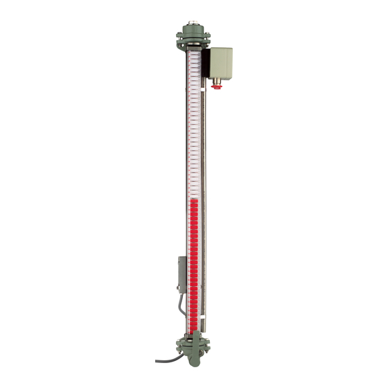
3 Product description 3.3 Design/versions Figure 2: Oil level indicator 1 Top part 2 Sealing ring 3 End cap 4 Clip 5 Oil conservator 6 Indicator rail 5793437-01 EN... -
Page 18: Nameplate
3 Product description 7 Magnetic flaps 8 Clip 9 Sealing ring 10 Oil drain screw 11 Stop valve 12 Bottom part 13 End cap 14 Measuring tube 15 Lower limit switch (optional) 16 Float gauge with magnet 17 Remote transmitter (optional) 18 Upper limit switch (optional) 19 Flat gaskets 3.4 Nameplate... -
Page 19: Packaging, Transport And Storage
4 Packaging, transport and storage 4.1 Purpose The packaging is designed to protect the packaged product during transport, loading, unloading and during periods of storage in such a way that no detri- mental changes occur. The packaging must protect the goods against per- mitted transport stresses such as vibration, knocks and moisture (rain, snow, condensation). - Page 20 4 Packaging, transport and storage Every delivered shipment must be checked for the following by the recipient before acceptance (acknowledgment of receipt): ▪ Completeness based on the delivery slip ▪ External damage of any kind. The checks must take place after unloading, when the box or transport con- tainer can be accessed from all sides.
-
Page 21: Storage Of Shipments
4 Packaging, transport and storage 4.5 Storage of shipments When selecting and setting up the storage location, ensure the following: ▪ Store the product and accessories in the original packaging until installa- tion. ▪ Protect stored goods against moisture (rain, flooding, water from melting snow and ice), dirt, pests such as rats, mice, termites etc. -
Page 22: Mounting
5 Mounting DANGER Electric shock! Danger of death due to electrical voltage when assembling/ disassembling the device. ► Switch off transformer on high-voltage side and low-voltage side. ► Lock transformer to prevent unintentional restart. ► Make sure that everything is de-energized. ►... -
Page 23: Attaching The Oil Level Indicator To The Oil Conservator
5 Mounting ▪ Sealing surface of the flanges on the oil conservator – Clean and undamaged – Without any damage along the radial surface such as scratches or points of impact – The surface quality of the sealing surface must be suited for the deliv- ered CENTELLEN®... - Page 24 5 Mounting 4. Attach the indicator rail to the measuring tube with the clips. The side of the indicator rail marked TOP must be on top. Inserting the float gauge into the measuring tube 1. Sweep with the float gauge over the indicator rail externally from top to bottom so that all magnetic flaps turn to white.
- Page 25 5 Mounting Attaching the oil level indicator to the oil conservator 1. Attach the oil level indicator to the oil conservator using flat gaskets. Only tighten the screws by hand. Figure 4: Attach the oil level indicator 5793437-01 EN...
- Page 26 5 Mounting NOTICE! A residual distance between the flanges caused by a deviation in evenness can cause damage to the flanges. Tighten screws with 10% of the target tightening torque and ensure that there is no gap between the flanges. If a gap is present, repair the affected oil conservator flanges or, if necessary, detach and re-weld them so that there is no longer a gap.
-
Page 27: Tests
5 Mounting Tightening screws in the top part and bottom part of the oil level indicator 1. Tighten screws in the top part and bottom part of the oil level indicator. 2. Fill the oil conservator with oil and open the stop valve. ð... -
Page 28: Attaching Limit Switches To The Measuring Tube
5 Mounting Incorrect oil level indication The following table shows possible causes for an incorrect oil level indica- tion. The measuring accuracy is ± 2 indicator flaps. Cause Action No oil in the oil conservator Fill the oil conservator with oil. Stop valve closed Open the stop valve. - Page 29 5 Mounting Figure 6: Limit switch 1 Measuring tube 2 Float gauge 3 Oil 4 Lower limit switch (N/C) 5 Upper limit switch (N/O) The wires of the connection cable for the limit switches are assigned as fol- lows: Wire Short- Until 06/2007 From 07/2007 Function...
- Page 30 5 Mounting Proceed as follows to install the limit switch. 1. Attach the limit switch, shifted 90° to the indicator rail, to the measuring tube using the clips supplied. In doing so, the cable must point downward. As the reed contact is mounted in the middle of the housing, the lowest value to be set is 50 mm above the top edge of the bottom part.
-
Page 31: Attaching The Remote Transmitter To The Measuring Tube
5 Mounting 3. Sweep a magnet over the limit switches externally in order to orient the limit switches as N/C or N/O contacts. Figure 8: Orienting the limit switches 4. Check the adjustment with an ohmmeter. 5.6 Attaching the remote transmitter to the measuring tube The measuring transducer installed in the remote transmitter converts the level-dependent change in resistance (3-wire potentiometer circuit) to an im- pressed output current of 4...20 mA. - Page 32 5 Mounting Proceed as follows to mount the remote transmitter. 1. Attach the remote transmitter, shifted 90° to the indicator rail, to the mea- suring tube using the clips supplied. Figure 9: Attach the remote transmitter 5793437-01 EN...
- Page 33 5 Mounting 2. Connect the supply voltage of 8…35 V DC to terminals 1 (+) and 2 (-). Figure 10: Connecting the remote transmitter 5793437-01 EN...
-
Page 34: Maintenance And Care
3. Check the device function (signaling and switches), see Tests. In the event of questions or irregularities, contact the Technical Service de- partment: Maschinenfabrik Reinhausen GmbH MR Service & Complaint Falkensteinstrasse 8 93059 Regensburg, Germany E-mail: service@reinhausen.com or complaint@reinhausen.com 5793437-01 EN... -
Page 35: Disposal
7 Disposal Observe the national disposal regulations in the country of use. 5793437-01 EN... -
Page 36: Technical Data
8 Technical data 8.1 Oil level indicator Measuring pipe 1.4571 stainless steel Float gauge Nitrophyl with integrated permanent magnet Indicator rail Makrolon, UV-resistant Table 6: Basic materials Diameter and wall thickness of the mea- 40 x 1 mm suring tube Standard lengths of the measuring tube 400 mm, 500 mm, 630 mm, 800 mm, 1000 mm, 1250 mm, other lengths on re- quest... -
Page 37: Remote Transmitter
8 Technical data 8.3 Remote transmitter Supply voltage 8…35 V DC Output signal I 4…20 mA Update rate 10 Hz Load resistance ≤ (V – 8 V) / 23 mA [Ω] supply Load stability < ±0.01 % of the presently selected range / 100 Ω [W] Signal in case of loop break ≤ 3.8 mA Response time 0.33 s... -
Page 38: Dimensional Drawing
8 Technical data 8.4 Dimensional drawing 5793437-01 EN... - Page 40 Messko GmbH Gewerbegebiet An den Drei Hasen Messko-Platz 1 61440 Oberursel, Germany +49 (0)6171 6398 0 messko-info@reinhausen.com www.reinhausen.com/messko ® 5793437-01 EN - MESSKO MMK - F0359701 - 02/20 - Messko GmbH 2020 THE POWER BEHIND POWER.
Need help?
Do you have a question about the MESSKO MMK and is the answer not in the manual?
Questions and answers