Sign In
Upload
Manuals
Brands
MR Manuals
Measuring Instruments
MSENSE BM
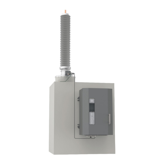
User Manuals: MR MSENSE BM Bushing Monitoring System
Manuals and User Guides for MR MSENSE BM Bushing Monitoring System. We have
2
MR MSENSE BM Bushing Monitoring System manuals available for free PDF download: Operating Instructions Manual
MR MSENSE BM Operating Instructions Manual (250 pages)
Monitoring system
Brand:
MR
| Category:
Measuring Instruments
| Size: 12 MB
Table of Contents
Table of Contents
3
Introduction
9
Manufacturer
9
Completeness
9
Safekeeping
9
Notation Conventions
9
Hazard Communication System
9
Information System
11
Instruction System
11
Typographic Conventions
12
Safety
13
Appropriate Use
13
Inappropriate Use
14
Fundamental Safety Instructions
14
Personnel Qualification
16
Personal Protective Equipment
17
Security
19
General
19
Commissioning
19
Operation
20
Interfaces
20
Encryption Standards
23
Product Description
26
MSENSE® BM Monitoring System Versions
26
Scope of Delivery
26
Function Description of MSENSE® BM-C
26
Function Description of MSENSE® BM-T
27
Performance Features
28
Operating Modes
29
Design
30
Bushing Adapter and Bushing Coupling Unit
31
Control Cabinet
31
ISM® Assemblies
32
Packaging, Transport and Storage
44
Packaging
44
Suitability
44
Markings
45
Transportation, Receipt and Handling of Shipments
46
Storage of Shipments
47
Unpacking Shipments and Checking for Transportation Damages
48
Mounting
51
Preparation
51
Installing the Bushing Adapter
52
Installing the Bushing Coupling Unit
55
Mounting the Control Cabinet
57
Installing the Cap Rail Modules
61
Minimum Distances
61
Fastening the Cap Rail
62
Installing the Bus Rail on the Cap Rail
63
Installing the Assembly at a Distance on the Cap Rail
64
Wiring the CPU I / CPU II Assembly
65
Wiring the UI Assembly
67
Wiring the DIO Assembly
69
Wiring the MC 2-2/SW3-3 Assembly
73
Wiring the QS3.241 Assembly
76
Connecting the Device
79
Cable Recommendation
79
Information about Connecting Serial Interfaces RS232 and RS485 (with 9-Pin Data Cable)
79
Information about Connecting Serial Interfaces RS232 and RS485 (with RJ45 Data Cable)
81
Information about Laying Fiber-Optic Cable
82
Connecting the Bushing Adapter to the Bushing Coupling Unit
83
Connecting the Bushing Coupling Unit to the Control Cabinet
84
Connecting the Voltage Transformers for the Reference System
87
Connecting Additional Leads (Optional)
89
Connecting the Power Supply
91
Checking Functional Reliability
92
Commissioning
93
Determining the Capacitance of the Bushings with BM-C
93
Determining the Capacitance and Dissipation Factor of the Bushings with BM-T
93
Setting the Language
93
Setting Date and Time
94
Setting the Parameters
94
Commissioning Wizard
94
Setting the Parameters Manually
95
Performing Standardization
97
Performing Tests
97
Ground Test
97
Performing Function Tests
98
High-Voltage Tests on the Transformer
98
Dielectric Tests on Transformer Wiring
99
Operation
100
Establishing a Connection to the Visualization (with CPU I / CPU II)
100
Establishing a Connection to the Visualization (with CPU / COM-ETH)
101
Operating Concept
103
General
105
Setting General Device Functions
106
Set up Automatic Logout
107
Activating/Deactivating Service User Access
108
Setting SNMP
109
Configuring the Network
110
Mqtt
113
Setting the Device Time
115
Configuring Syslog
118
Scada
120
Configuring IEC 61850 (Optional)
120
Configuring IEC 60870-5-101 (Optional)
122
Configuring IEC 60870-5-103 (Optional)
125
Configuring IEC 60870-5-104 (Optional)
127
Configuring Modbus (Optional)
129
Configuring DNP3 (Optional)
131
Configure Data Points (Optional)
133
Setting the Measured Value Recorder
141
Linking Signals and Events
142
Linking Digital Outputs
142
Linking Control System Messages
143
Setting the Transformer Data for the Reference System (Optional)
145
Circuit Breaker Monitoring
146
Configuring Bushing Monitoring
146
Set the Field Designation
146
Configuring Capacitance Monitoring
147
Configuring Dissipation Factor Monitoring (MSENSE® BM-T)
151
Sum Current Method
154
Displaying the State of the Bushings
156
Displaying the Capacitance Progression
157
Show Dissipation Factor Curve (MSENSE® BM-T)
157
Displaying Sum Current Information
158
Displaying Measured Value Recorder (Optional)
159
Configuring Digital Inputs and Outputs
160
Event Management
162
Displaying and Acknowledging Events
162
Configuring Events
163
Displaying Event Memory
164
Exporting the Event Messages Overview
165
User Administration
166
User Roles
166
Changing the Password
167
Creating, Editing and Deleting Users
168
Setting Access Rights to Parameters and Events
170
User Authentication Via RADIUS (Optional)
171
Information about Device
174
Hardware
174
Software
174
Import/Export Manager
176
Exporting Data
176
Importing Data (Software Version 3.753 and Later)
177
Configuring Media Converter with Managed Switch
179
Commissioning
179
Configuration
180
Transformer Personal Logic Editor (TPLE)
182
Function
182
Configuring TPLE
195
Inspection and Maintenance
199
Care
199
Inspection
199
Maintenance
199
Fault Elimination
200
General Faults
200
Signal Lights and Digital Outputs
200
Human-Machine Interface
201
Other Faults
201
Uninstallation
203
Removing the Control Cabinet
203
Removing the Bushing Adapter and Bushing Coupling Unit
205
Disposal
206
Technical Data
207
Bushing Adapter
207
Bushing Coupling Unit
210
Connection Cable
211
Control Cabinet
211
ISM® Assemblies
212
Connection Terminals
212
Power Supply
212
Central Processing Unit
213
Voltage Measurement and Current Measurement
218
Digital Inputs and Outputs
221
Analog Inputs and Outputs
231
System Networking
235
Appendix
239
Measured Log Value of the Bushings, Field 1
239
Measured Log Value of the Bushings, Field 2
240
Advertisement
MR MSENSE BM Operating Instructions Manual (190 pages)
Monitoring system
Brand:
MR
| Category:
Measuring Instruments
| Size: 8 MB
Table of Contents
Table of Contents
3
1 Introduction
8
Manufacturer
8
Completeness
8
Safekeeping
8
Notation Conventions
8
Hazard Communication System
8
Information System
10
Instruction System
10
Typographic Conventions
11
2 Security
12
Appropriate Use
12
Inappropriate Use
13
Fundamental Safety Instructions
13
Personnel Qualification
15
Personal Protective Equipment
16
3 Security
18
4 Product Description
21
Scope of Delivery
21
Function Description
21
Performance Features
22
Operating Modes
23
Design
24
Bushing Adapter and Bushing Coupling Unit
25
Control Cabinet
25
DIO 28-15 Digital Inputs and Outputs
28
5 Packaging, Transport and Storage
31
Packaging
31
Suitability
31
Markings
32
Transportation, Receipt and Handling of Shipments
32
Storage of Shipments
33
Unpacking Shipments and Checking for Transportation Damages
34
6 Mounting
36
Preparation
36
Installing the Bushing Adapter
36
Installing the Bushing Coupling Unit
38
Fitting the Control Cabinet to the Transformer
41
Connecting the Device
43
Cable Recommendation
43
Information about Connecting Serial Interfaces RS232 and RS485
44
Information about Laying Fiber-Optic Cable
47
Connecting the Bushing Adapter to the Bushing Coupling Unit
47
Connecting the Bushing Coupling Unit to the Control Cabinet
48
Connecting the Voltage Transformers for the Reference System
53
Connecting Additional Leads (Optional)
54
Connecting the Power Supply
55
Checking Functional Reliability
56
7 Commissioning
57
Determining the Capacitance and Dissipation Factor of the Bushings
57
Establishing Connection to Visualization
57
Setting the Language
59
Setting Date and Time
60
Setting the Parameters
60
Commissioning Wizard
60
Setting the Parameters Manually
61
Performing Standardization
62
Performing Tests
62
Performing Function Tests
62
Electrical High-Voltage Tests on the Transformer
63
Dielectric Tests on Transformer Wiring
63
8 Operation
64
Establishing Connection to Visualization
64
Operating Concept
65
General
67
Setting General Device Functions
67
Set up Automatic Logout
68
Activating/Deactivating Service User Access
69
Configuring the Network
69
Setting the Device Time
72
Configuring Syslog
74
Scada
75
Configuring IEC 61850 (Optional)
76
Configuring IEC 60870-5-101 (Optional)
78
Configuring IEC 60870-5-103 (Optional)
81
Configuring IEC 60870-5-104 (Optional)
84
Configuring Modbus (Optional)
85
Configuring DNP3 (Optional)
87
Configure Data Points (Optional)
89
Linking Signals and Events
97
Linking Digital Outputs
98
Linking Control System Messages
99
Setting the Transformer Data for the Reference System (Optional)
100
Circuit Breaker Monitoring
101
Configuring Bushing Monitoring
102
Set the Field Designation
102
Configuring Capacitance Monitoring
103
Configuring Dissipation Factor Monitoring
107
Displaying the State of the Bushings
108
Displaying the Capacitance Progression
109
Displaying the Dissipation Factor Progression
110
Displaying Measured Value Recorder (Optional)
110
Configuring Digital Inputs and Outputs
112
Event Management
114
Displaying and Acknowledging Events
114
Configuring Events
115
Displaying Event Memory
116
User Administration
117
User Roles
118
Changing the Password
119
Creating, Editing and Deleting Users
120
Setting Access Rights to Parameters and Events
122
User Authentication Via RADIUS (Optional)
123
Information about Device
125
Hardware
125
Software
126
Import/Export Manager
126
Exporting Data
126
Importing Data (Software Version 3.44 and Later)
128
Configuring Media Converter with Managed Switch
129
Commissioning
129
Configuration
131
TAPCON® Personal Logic Editor (TPLE)
132
Function
132
Configuring TPLE
145
9 Inspection and Maintenance
149
Care
149
Inspection
149
Maintenance
149
10 Fault Elimination
150
General Faults
150
Signal Lights and Digital Outputs
150
Human-Machine Interface
151
Other Faults
151
11 Messages
153
Event Messages
153
12 Uninstallation
164
Removing the Control Cabinet
164
Removing the Bushing Adapter and Bushing Coupling Unit
166
13 Disposal
168
14 Technical Data
169
Bushing Adapter
169
Bushing Coupling Unit
172
Control Cabinet
173
Connection Terminals
174
CPU (Central Processing Unit) I
178
System Networking
180
Bus Extension Module
181
Connection Cable
182
15 Appendix
183
Measured Value Log
183
Glossary
185
List of Key Words
186
Advertisement
Related Products
MR MESSKO BeTech
MR MESSKO MMK
MR MESSKO MFLOC 2.0
MR MTO-ST160
MR MTO-ST160TT
MR MTO-ST160TTM
MR MTO-STF160
MR MTO-STF160TT
MR MTO-ST160V
MR MTO-ST160VTTM
MR Categories
Industrial Equipment
Controller
Measuring Instruments
Thermometer
Control Systems
More MR Manuals
Login
Sign In
OR
Sign in with Facebook
Sign in with Google
Upload manual
Upload from disk
Upload from URL