Table of Contents
Advertisement
Quick Links
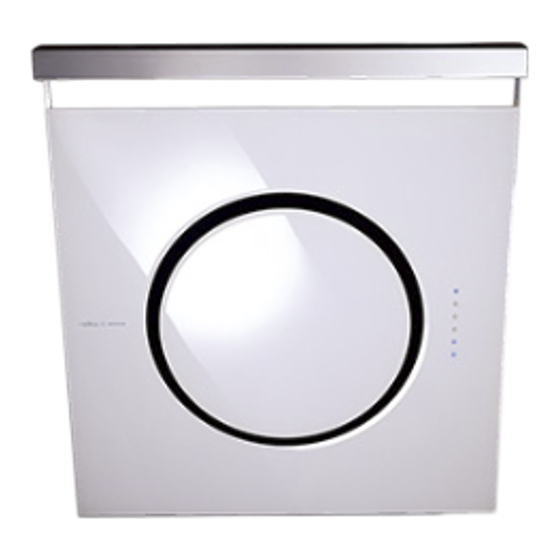
EOM-M80AW
EOM-M80AB
Model number:
Numéro de modèle: ____________________________________
Número de modelo:
Serial number:
Numéro de série : _____________________________________
Número de serie:
Date of Purchase:
Date d'achat :
Fecha de compra:
Sales Dealer:
Détaillant:
Distribuidorr:
JAN06.0101
READ AND SAVE THESE INSTRUCTIONS
LISEZ CES INSTRUCTIONS ET CONSERVEZ-LES
LEAYGUARDE ESTAS INSTRUCCIONES
Om
_____________________________________
_____________________________________
www.zephyronline.com
Advertisement
Table of Contents

Related Manuals for Zephyr Elica Om


Summary of Contents for Zephyr Elica Om
- Page 1 www.zephyronline.com EOM-M80AW EOM-M80AB Model number: Numéro de modèle: ____________________________________ Número de modelo: Serial number: Numéro de série : _____________________________________ Número de serie: Date of Purchase: Date d’achat : _____________________________________ Fecha de compra: Sales Dealer: Détaillant: _____________________________________ Distribuidorr: JAN06.0101 READ AND SAVE THESE INSTRUCTIONS LISEZ CES INSTRUCTIONS ET CONSERVEZ-LES LEAYGUARDE ESTAS INSTRUCCIONES...
- Page 2 E page F page S page APPROVED FOR RESIDENTIAL APPLIANCES FOR RESIDENTIAL USE ONLY READ AND SAVE THESE INSTRUCTIONS PLEASE READ ENTIRE INSTRUCTIONS BEFORE PROCEEDING. INSTALLATION MUST COMPLY WITH ALL LOCAL CODES. IMPORTANT: Save these Instructions for the Local Electrical Inspector’s use. INSTALLER: Please leave these Instructions with this unit for the owner.
-
Page 3: Table Of Contents
www.zephyronline.com Important safety Notice ..............4 Electrical & Installation requirements ..........5 Electrical requirements .............. 5 Before installing the hood ............5 List of Materials ................. 6 Parts supplied: ................6 Parts not supplied ..............6 Dimensions and clearances .............. 7 Installation Instructions .............. -
Page 4: Important Safety Notice
READ AND SAVE THESE INSTRUCTIONS CAUTION: FOR GENERAL VENTILATING USE ONLY. DO NOT USE TO EXHAUST HAZARDOUS OR EXPLOSIVE MATERIALS OR VAPORS. WARNING TO REDUCE THE RISK OF FIRE, ELECTRIC SHOCK, OR INJURY TO PERSONS, OBSERVE THE FOLLOWING: A. Use this unit only in the manner intended by the manufacturer. If you have questions, contact the manufacturer. B. -
Page 5: Electrical & Installation Requirements
www.zephyronline.com ELECTRICAL REQUIREMENTS Important: Observe all governing codes and ordinances. It is the customer’s responsibility: • To contact a qualified electrical installer. • To assure that the electrical installation is adequate and in conformance with National Electrical Code, ANSI/NFPA 70 —... -
Page 6: List Of Materials
PARTS SUPPLIED: • Blower unit housing • Top cover • Hood canopy • Metal grease filter x 1 • Halogen light bulb x 2 • Hardware Packet: Remote Control Transition for Rear/Horizontal discharge + backdraft damper Allen spanner x 1 Hook x 2 Rubber tape (section in mm: 20x5) for back of range hood Rubber tape (section in mm: 8x8) for hear/horizontal discharge Transition... -
Page 7: Dimensions And Clearances
www.zephyronline.com 17" 1/2 22" 1/16 31" 1/2 min 47" 14/16*** max 65" 3/16*** min 38" 13/16** max 47" 8/16** 29" 7/16 33" 15/16 7" 1/16 13" 3/4 2" 3/8 ceiling rear 1" 1/4 wall Conduit (vertical-horizontal discharge) and Ducting area 13"... -
Page 8: Installation Instructions
Closely follow the instructions set out in this manual. All responsibility, for any eventual inconveniences, damages or fires caused by not complying with the instructions in this manual, is declined. VENTING METHODS The hood is equipped to discharge of fumes to the outside towards the rear (Ducting version - Horizontal discharge). Fumes may be discharged towards the top side (Ducting version - Vertical discharge). -
Page 9: Installation - Ductwork Calculation Sheet
www.zephyronline.com Duct pieces Equivalent number Duct pieces Equivalent number lenght x used = Total lenght x used = Total 3 1/4 ” x 10” 1 Ft. 6" Round 30 Ft. x ( Rect., wall cap straight with damper 6 ” Round,, 1 Ft. -
Page 10: Installation- Discharge Direction
This hood is shipped ready for Horizontal c. Remove the screws that fix the electronic box to discharge. To change to Vertical discharge proceed the back of the hood and release the box as follows: towards the bottom of the motor housing, so to Note1: when proceeding keep all screws and leave anough clearance to handle the blower. - Page 11 www.zephyronline.com e. Remove the blower from the metal filter housing. f. Reposition the blower/bracket assembly so that discharge outlet is towards the top side (Vertical discharge), firmly tighten the 4 fixing screws. WARNING! When performing this step check that wirings run in a proper way, DO NOT DAMAGE OR PULL WIRINGS! Horizontal Vertical...
-
Page 12: Installation
Installation 8. Note: all fastener locations must span the studs otherwise proceed as follows: 1. If possible, disconnect and move freestanding or Cutout drywall along marked lines. Install each slide-in range from cabinet opening to provide necessary between studs firmly flush with already easier access to rear wall. - Page 13 www.zephyronline.com 10. Ducting Version-horizontal discharge ONLY: 11. Determine position of the conduit and cut a 1-1/4" Connect ducting to transition for horizontal (3.2 cm) hole at this location. Position the conduit. discharge, seal with duct tape and fix transition to Run wires through hole according the National the wall with four screws, use the included Electrical Code or CSA Standards and local codes...
-
Page 14: 19. Electrical Connection
15. Hang hood on hooks with the 2 brackets. 18. Ducting version - vertical discharge ONLY: Install the transition on top of the hood with 2 WARNING screws. Excessive Weight Hazard - Use two or more people Connect ducting to transition. Seal with duct tape. to move and install range hood. - Page 15 www.zephyronline.com Connect black wire from service panel to black or red in Controls start flashing for about 15 secs to indicate junction box, white to white and green to green-yellow. they are calibrating themselves, wait until flashing stops (only Motor touch sensor key OFF (stand by) Close junction box cover.
-
Page 16: Description Of The Hood
1 Control panel 2 Grease filter 3 Grease filter release handle 4 Halogen lamp (position and nr. of lamps may vary) 5 Front door 6 Air outlet (on top and on the rear side) -
Page 17: Controls
www.zephyronline.com Use the high suction speed in cases of concentrated kitchen vapours. It is recommended that the cooker hood suction is switched on for 5 minutes prior to cooking and to leave in operation during cooking and for another 15 minutes approximately after terminating cooking. -
Page 18: Remote Control
Using the Remote Control This device complies with part 15 of the FCC Rules. Operation is subject to the following two conditions: (1) This device may not cause harmful interference, and (2) this device must accept any interference received, including interference that may cause undesired operation. The remote control may operate in humid environments, but not when placed on wet surfaces. -
Page 19: Maintenance
www.zephyronline.com Prior to any maintenance operation ensure that the GREASE FILTER cooker hood is disconnected from the power supply. This must be cleaned once a month using non aggres- sive detergents, either by hand or in the dish-washer, CLEANING which must be set to a low temperature and a short The cooker hood should be cleaned regularly internally cycle. -
Page 20: Trouble Shooting
Issue Cause What to do After installation, the 1. The power source is not turned ON. 1. Make sure the circuit breaker and the unit doesn’t work? unit’s power is ON. 2. The power line and the cable locking 2. Check the power connection with the connector is not connecting properly. -
Page 21: Warranty
Product damaged through negligence, misuse, abuse, accident. Improper installation and failure to follow installation instructions. When product is used commercially or other than its intended purpose. Damaged because of improper connection with equipment of other manufacturers. Repaired or modified by anyone other than Zephyr’s Authorized Agents. What is Not Covered: Consumable parts such as light bulbs, filters, and fuses. -
Page 22: List Of Parts And Accessories
Part Description Part# Z0B-0009 halogen bulb, 12V 20 W metal filter GF009C remote control battery ..394 of 1.5V. (4 needed) Part Description Part# ZRC-00OM Ductless Recirculating Kit charcoal replacement filter Z0F-C061 Low duct cover kit Z0C-00OM High duct cover kit Z1C-00OM... - Page 23 www.zephyronline.com...
Need help?
Do you have a question about the Elica Om and is the answer not in the manual?
Questions and answers