
Related Manuals for Uplift Desk FRM240


Summary of Contents for Uplift Desk FRM240
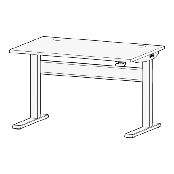
- Page 1 Pneumatic Standing Desk FRM240 For assembly assistance, two person visit upliftdesk.com/contact, assembly or call 800-349-3839, or email info@upliftdesk.com 355 lb ©2023 UPLIFT Desk®. All Rights Reserved...
-
Page 2: Safety And Warnings
WARNING: Inspect the desk regularly and stop using immediately if you notice any damaged or loose parts. Only replace damaged desk parts with authorized UPLIFT Desk parts and follow instructions. Please read these instructions carefully. This desk is height adjustable to fit the user’s height. - Page 3 Note: Desk image is for reference only. Desk shape and leg quantity or style may change based on the desk configuration ordered. © UPLIFT Desk • 800-349-3839 • info@upliftdesk.com • upliftdesk.com...
-
Page 4: Package Contents
Package Contents Legs Feet Crossbar Crossbar Rail Right Side Bracket qty 2 qty 2 Left Side Bracket Cross Brace Control Cover Screw Cover Badge qty 2 Paddle Adapter qty 2 M6 x 10 M6 x 6 M5 x 12 Flat #10 x 3/4”... - Page 5 M6 x 10 Machine Screws through the holes, but do not tighten them. © UPLIFT Desk • 800-349-3839 • info@upliftdesk.com • upliftdesk.com...
- Page 6 E. Place one of the Feet (C2) onto one of the Legs as shown, with the longer end of the foot facing up and away from the side of the Legs with the Crossbar Mounts. F. Loosely start four of the M6 x 10 Machine Screws (H1) using the 4mm Allen Wrench (H8).
- Page 7 Side Brackets as shown. E. Once all four screws have been started in each Side Bracket, tighten them using the 3mm Allen Wrench (H7). © UPLIFT Desk • 800-349-3839 • info@upliftdesk.com • upliftdesk.com...
- Page 8 Step 7 - Cross Brace Attachment A. Orient the Cross Braces (C7) with the counter-sink (larger) side of the holes facing up as shown. B. Align the Cross Braces with the holes near the center of the Crossbar Rails (C4) as shown and loosely insert two M5 x 12 Flat Head Screws (H3) through the counter-sunk holes of each Cross Brace and into the Crossbar Rails.
- Page 9 Control Paddle Adapter (C8) attached. When positioning your frame on the desktop, lift it up. DO NOT SLIDE THE FRAME. This will help protect the underside of your desktop from scratches. © UPLIFT Desk • 800-349-3839 • info@upliftdesk.com • upliftdesk.com...
- Page 10 D. Carefully position the frame so that the three holes in each Side Bracket align with the metal threaded inserts along the sides of the desktop. E. Loosely insert three of the #10-24 x 3/4” Machine Screws (H5) with #10 Flat Washers (H6) through the holes in the Side Brackets and into the threaded metal inserts at the sides of the desktop using a Phillips head screwdriver.
-
Page 11: Step 12 - Desk Placement
Do not place any objects underneath the desk taller than the underside of the desk when it is in the lowered position. © UPLIFT Desk • 800-349-3839 • info@upliftdesk.com • upliftdesk.com... - Page 12 Copyright Notice: This guide is a component of this UPLIFT Desk product. This guide is a part of © the scope of delivery, even if the item is resold. This guide is also available on the UPLIFT Desk website: upliftdesk.com. These specifications are subject to United States copyright law.
Need help?
Do you have a question about the FRM240 and is the answer not in the manual?
Questions and answers