
Related Manuals for Uplift Desk FRM067


Summary of Contents for Uplift Desk FRM067
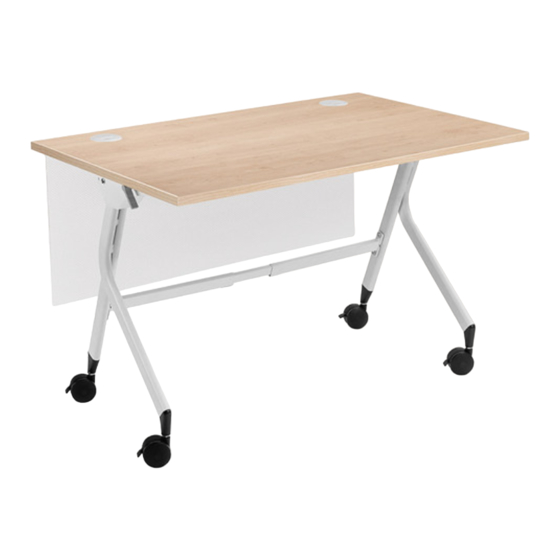
- Page 1 Flip Top Table FRM067 For assembly assistance, two person visit upliftdesk.com/contact, assembly or call 800-349-3839, or email info@upliftdesk.com 355 lb ©2022 UPLIFT Desk®. All Rights Reserved...
- Page 2 WARNING: Inspect the table regularly and stop using immediately if you notice any damaged or loose parts. Only replace damaged parts with authorized UPLIFT Desk parts and instructions. WARNING: The table is designed for use in dry environments, indoors only.
- Page 3 L. Upper Crossbar end R. Upper Crossbar end Lower Crossbar end Crossbar rail Tools required (not provided) sbar end R. Upper Crossbar end Lower Crossbar end Crossbar rail Tape Measure Phillips Head Screwdriver © UPLIFT Desk • 800-349-3839 • info@upliftdesk.com • upliftdesk.com...
-
Page 4: Component Diagram
Component Diagram Left Leg Assembly Left Upper Crossbar End Latch Release Crossbar End Lower Crossbar End Crossbar Rail Latch Release Crossbar Rail Right Upper Crossbar End Crossbar Rail Right Leg Assembly Lower Crossbar End Caster... -
Page 5: Step 1 - Inventory Of Parts
D. Using the long end of the 5mm Allen Wrench (H6) through the access holes in the Leg Assembly mounting plate, tighten the screws. E. Repeat this step for the Left Leg Assembly (P1L) and Left Upper Crossbar End (P2L). © UPLIFT Desk • 800-349-3839 • info@upliftdesk.com • upliftdesk.com... - Page 6 Step 3 - Lower Crossbar End Attachment A. Starting with the Right Leg Assembly (P1R), align one of the Lower Crossbar Ends (P3) with the circled end in the image facing up. B. Loosely insert two M8 x 20 Machine Screws (H2) through the Lower Crossbar End holes and into the Leg Assembly, but do not tighten them yet.
- Page 7 Step 6 - Leg Assembly Attachment (Left Side) A. Slide the Upper Crossbar End (P2L) and Lower Crossbar End (P3) of the Left Leg Assembly (P1L) onto the ends of the two Crossbar Rails (P4) as shown. © UPLIFT Desk • 800-349-3839 • info@upliftdesk.com • upliftdesk.com...
- Page 8 B. Align the holes in the Left Leg Assembly with the metal threaded inserts in the tabletop. C. Loosely insert four #10-24 x 3/4” Machine Screws (H4) and #10 Flat Washers (H5) through the frame holes and into the four metal threaded inserts in the tabletop.
- Page 9 (10mm) away from the inside of the Leg Assembly bracket. Insert one M6 x 10mm Set Screw (H1) in the hole and tighten using the 3mm Allen Wrench. Insert one M6 x 10mm Set Screw © UPLIFT Desk • 800-349-3839 • info@upliftdesk.com • upliftdesk.com...
-
Page 10: Step 9 - Caster Installation
E. Repeat previous two steps to attach the other Latch Release Crossbar End to the opposite Leg Assembly. F. Slide the Latch Release Crossbar Rail left or right as needed until it is approximately centered between the two Leg Assemblies as shown. G. - Page 11 B. Remove the backing on each Rubber Bumper and press it firmly for 20 to 30 seconds onto the bottom side of the tabletop where it makes contact with one of the Leg Assemblies. © UPLIFT Desk • 800-349-3839 • info@upliftdesk.com • upliftdesk.com...
- Page 12 © Copyright Notice: This guide is a component of this UPLIFT Desk product. This guide is a part of the scope of delivery, even if the item is resold. This guide is also available on the UPLIFT Desk website: upliftdesk.com. These specifications are subject to United States copyright law.
Need help?
Do you have a question about the FRM067 and is the answer not in the manual?
Questions and answers