Table of Contents
Advertisement
Quick Links
Advertisement
Table of Contents

Related Manuals for Uplift Desk F550


Summary of Contents for Uplift Desk F550
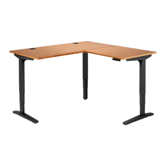
- Page 1 V2 L-Shaped Standing Desk Work Better. Live Healthier F550 - F551 Two person Scan QR code for assembly product webpage For assembly assistance, visit upliftdesk.com/contact, call 800-349-3839, or email support@upliftdesk.com ©2023 UPLIFT Desk®. All Rights Reserved. US patent no. 11,109,672 B2...
- Page 2 WARNING: Never use the desk if the power cord or plug becomes damaged as this can cause a risk of fire and electric shock. Contact UPLIFT Desk for a replacement power cord if it is damaged in any way. WARNING: Risk of serious injury or death.
- Page 3 Desk image is for reference only and may not match your desk style. > 1” vertical gap Max height > 1” horizontal gap Min height Do not place feet on items below the desk where they can be injured. © UPLIFT Desk • 800-349-3839 • info@upliftdesk.com • upliftdesk.com...
-
Page 4: Package Contents
Package Contents Frame Components (ships in multiple boxes) Foot Peg Foot Crossbar End Short Corner Long Corner qty 2 qty 3 qty 2 Crossbar End Crossbar End Side Bracket Corner Anchor Plate Crossbar Rail Keypad Control Box qty 2 qty 2 qty 4 Side Bracket Type varies... -
Page 5: Parts Diagram
Parts Diagram Corner Side Bracket Short Corner Crossbar End Long Corner Crossbar End Crossbar Rail Crossbar End Crossbar End Logo Plate Side Bracket Side Bracket Foot © UPLIFT Desk • 800-349-3839 • info@upliftdesk.com • upliftdesk.com... - Page 6 Assembly Instructions Step 1 - Inventory of Parts A. To avoid damage to your floor or desktop, assemble the desk on a clean carpet or blanket. B. Lay out all parts from each box and ensure you have everything listed in the package contents of this manual before throwing away any packaging.
-
Page 7: Step 5 - Attach Feet
C. Tighten screws using the 4mm Allen Wrench (H6) attached to the Allen Wrench Handle (H15) to provide Long end of more leverage when tightening screws. side Bracket © UPLIFT Desk • 800-349-3839 • info@upliftdesk.com • upliftdesk.com... - Page 8 IMPORTANT: Tighten Foot screws very thoroughly to ensure the stability of the desk. Long ends D. Repeat the previous steps to attach the second Foot. Long ends Tighten screws very thoroughly. IMPORTANT: Retighten each screw again to ensure that all screws are VERY tight before proceeding. Tightening these screws has a noticeable impact on desk stability.
- Page 9 C. Tighten screws using the 4mm Allen Wrench (H6) attached to the Allen Wrench Handle (H15). IMPORTANT: Tighten Foot screws very thoroughly to ensure the stability of the desk. Completed center Leg assembly. © UPLIFT Desk • 800-349-3839 • info@upliftdesk.com • upliftdesk.com...
- Page 10 Step 10 - Insert Crossbar Rails into Right Leg Assembly A. Insert a Crossbar Rail (P12) into each of the two openings at the end of the Crossbar End (P4) of the right Leg assembly shown. B. Slide the Crossbar Rails as far as they will go into the Crossbar End.
- Page 11 Bottom surface of desktops Bottom surface of desktops arranged for a left return. arranged for a right return. Main Main Left return Right return Keypad mounting holes Keypad mounting holes © UPLIFT Desk • 800-349-3839 • info@upliftdesk.com • upliftdesk.com...
- Page 12 Step 13 - Place Leg Assemblies from Step 11 onto Desktops Leg assemblies are positioned on the main and return desktops in the same orientation regardless of whether the return will be on the left or right side. A. With the help of a friend, pick up and place the Leg assemblies from Step 11 onto the desktops as shown below for either the right or left return orientation.
- Page 13 Step 16 - Place & Attach Remaining Leg Assembly A. Position the remaining Leg assembly as shown and slide the Crossbar End (P4) onto the ends of the Crossbar Rails (P12). Desk with left return. Desk with right return. © UPLIFT Desk • 800-349-3839 • info@upliftdesk.com • upliftdesk.com...
- Page 14 B. Align the holes in the Side Bracket and Crossbar End with the pre-drilled holes or metal threaded inserts in the desktop. C. Use a Phillips Screwdriver to insert a Screw (H4a or H4b) and Washer (H5) through each of the holes shown in the Side Bracket and Crossbar End and into the pre-drilled holes or metal threaded inserts in the desktop.
- Page 15 C. If your Casters have a hex nut between the threaded stem and wheels, you can use a 1⁄2” (12mm) or adjustable wrench (not included) to assist with the Caster installation process. © UPLIFT Desk • 800-349-3839 • info@upliftdesk.com • upliftdesk.com...
- Page 16 Step 20 - Separate Main & Return Desk Sections The desk will be flipped upright for the remainder of the assembly. Flipping the return and main desk sections individually is much easier and safer than attempting to flip the complete L-shaped desk assembly. It can also prevent damage to the desk assembly.
- Page 17 End and tighten using the 4mm Allen Wrench (H6). IMPORTANT: Ensure that all set screws are making contact with the Crossbar Rails inside the Crossbar Ends and are tight before proceeding. © UPLIFT Desk • 800-349-3839 • info@upliftdesk.com • upliftdesk.com...
-
Page 18: Step 24 - Connect Cables
F. Connect the Keypad cable into the Control Box port labeled “HS”. The Control Box port labeled “F” is used to connect the Bluetooth Adapter (FRM125) for use with the UPLIFT Desk App. The Control Box port labeled “DC” is used to power low voltage accessories with compatible connectors. -
Page 19: Accessory Installation
B. Use a Phillips Screwdriver to attach the Tray to your desktop using two #10 x 5/8” Wood Screws (H14). © UPLIFT Desk • 800-349-3839 • info@upliftdesk.com • upliftdesk.com... - Page 20 Install Accessory Anchor Plates (optional) Some UPLIFT Desk accessories are designed to attach to the patented mounting points located on front and back of the Crossbar Ends. Some of these accessories require the use of the included Anchor Plates (P11). Refer to the instructions provided with each accessory for specific mounting instructions.
- Page 21 10. Try operating the desk again. If the desk is working properly, you’re done and the desk is ready to use. If you have an Advanced Keypad, see the Programming section below for further information on how to use your Keypad. © UPLIFT Desk • 800-349-3839 • info@upliftdesk.com • upliftdesk.com...
-
Page 22: Keypad Lock
Programming (Advanced Keypads only) These UPLIFT Desk programming instructions are compatible with all UPLIFT Advanced Keypads except the Advanced Paddle Keypad. For Advanced Paddle Keypad programming steps, refer to the instructions provided with that Keypad. Set & Use Memorized Heights... - Page 23 4. Wait for the display to change back to “ASr.” 5. Hold the “down” button until the desktop lowers and rises slightly and the display changes back to the numeric height setting. © UPLIFT Desk • 800-349-3839 • info@upliftdesk.com • upliftdesk.com...
-
Page 24: Starting And Stopping
Study this manual carefully. If this product is sold, please provide this manual to the buyer, installers, or support personnel operating the product. Copyright Notice: This manual is a component of this UPLIFT Desk product. This manual is a ©...
Need help?
Do you have a question about the F550 and is the answer not in the manual?
Questions and answers