Verathon GlideScope Core Operation & Maintenance Manual
Hide thumbs
Also See for GlideScope Core:
- Operation & maintenance manual (84 pages) ,
- Operators & service manual (19 pages) ,
- Operation & maintenance manual (64 pages)
Table of Contents
Advertisement
Advertisement
Table of Contents

Related Manuals for Verathon GlideScope Core


Summary of Contents for Verathon GlideScope Core
- Page 1 GlideScope Core ® Operations & Maintenance Manual...
- Page 2 0900‑5017 REV‑07...
- Page 3 GlideScope Core Operations & Maintenance Manual Effective: March 20, 2023 Caution: Federal (United States) law restricts this device to sale by or on the order of a physician. GlideScope Core ®...
- Page 4 Switzerland Switzerland Copyright © 2023 by Verathon Inc. All rights reserved. No part of this manual may be copied or transmitted by any method without the express written consent of Verathon Inc. GlideScope, GlideScope BFlex, GlideScope Core, GVL, GlideRite, QuickConnect, MagnaView, Spectrum, Verathon, and all associated symbols are trademarks or registered trademarks of Verathon Inc.
-
Page 5: Table Of Contents
Environments of Intended Use ..........................1 Essential Performance ...............................1 HIPAA Privacy ................................1 Notice to All Users ..............................2 Warnings & Cautions..............................2 INTRODUCTION ................................6 GlideScope Core ................................6 System Parts & Accessories ............................7 Buttons, Icons, & Connections ...........................9 SYSTEM FEATURES ..............................15 Home Screen ................................15 Gallery ..................................16 SETTING UP................................17... - Page 6 Procedure 5. Record Video or Take a Snapshot ....................37 Procedure 6. Use the Gallery ..........................38 REPROCESSING ...............................43 MAINTENANCE & SAFETY ............................44 Periodic Inspections ..............................44 GlideScope Core Battery ............................44 System Software ..............................44 Device Repair ................................45 Device Disposal ................................45 LIMITED WARRANTY ..............................46 PRODUCT SPECIFICATIONS ..........................48...
-
Page 7: Important Information
(Core 10) or Dual View (Core 15) options. Product Description GlideScope Core is an all-in-one system offering immediate access to the tools you need to visualize the airway. Designed around a 10” or 15” high-definition, touchscreen monitor and comprehensive workstation, GlideScope Core delivers elevated visibility and improved workflow. -
Page 8: Notice To All Users
Notice to All Users Verathon recommends that all users read this manual before using the system. Failure to do so may result in injury to the patient, may compromise the performance of the system, and may void the system warranty. - Page 9 This product may only be cleaned by using the approved processes provided in the GlideScope and GlideRite Products Reprocessing Manual (part number 0900-5032). Cleaning methods listed are recommended by Verathon based on efficacy or compatibility with component materials. Warnings: Product Safety...
- Page 10 Use only the accessories and peripherals recommended by Verathon. WARNING Electric shock hazard. Do not attempt to open the system components. This may cause serious injury to the operator or damage to the instrument and voids the warranty. Contact Verathon Customer Care for all servicing needs. WARNING Stored mechanical energy hazard.
- Page 11 The system contains electronics that may be damaged by ultrasonic and automated washing equipment. Do not use an ultrasonic device or automated washing equipment, other than Verathon-approved systems, to clean this product. CAUTION Ensure that you do not use any abrasive brushes, pads, or tools when cleaning the video monitor screen.
-
Page 12: Introduction
Titanium video laryngoscopes must be cleaned and high-level disinfected between uses. These connect to the video monitor through the reusable GlideScope Core Video Cable. Due to their titanium construction, reusable video laryngoscopes contain a T in the blade name, such as LoPro T4. -
Page 13: System Parts & Accessories
System Parts & Accessories Table 1. Required System Components REQUIRED PARTS & ACCESSORIES GlideScope Core video monitor GlideScope Core 10 GlideScope Core 10 FHD GlideScope Core 15 GlideScope Core 15 FHD 12V DC power adapter Power cable Video cable *†... - Page 14 REQUIRED PARTS & ACCESSORIES BFlex Single-Use Bronchoscopes Table 2. Optional System Components OPTIONAL PARTS & ACCESSORIES Premium workstation (0800-0557) Premium workstation (0800-0636) Nonin 3231 USB GlideRite Stylets Media storage USB Operations & ‡ External Pulse Maintenance Manual USB Oximeter † * For a full list of single-use bronchoscopes, please see the GlideScope BFlex Single‑Use Bronchoscopes Operations &...
-
Page 15: Buttons, Icons, & Connections
Buttons, Icons, & Connections The digital, full-color GlideScope Core Video Monitor clearly displays the images transmitted from the camera in the scope. The front of the monitor includes the button for power and the touchscreen. The back panel of the monitor includes sockets and ports for connecting the power cord, video cables, USB flash drives, and an HDMI cable for an external video display. - Page 16 BUTTON BUTTON FUNCTION GROUP Gallery: Launches Gallery page. If there is an error, the icon changes to include an Attention symbol: Main Menu Settings: Launches Settings page. Flyout Video Rotation: Pressing this button rotates video feed(s) 180-degrees. Can be enabled or disabled in the Feature Settings Tab.
- Page 17 BUTTON BUTTON FUNCTION GROUP Export: Exports selected file. Star: Adds or removes ‘favorite’ status to selected file. Delete: Deletes selected file. Back: Returns to previous screen. Select All: When viewing files in the Gallery, check this box to select all files in Gallery the row.
- Page 18 BUTTON BUTTON FUNCTION GROUP Restart: Rewinds selected video to beginning. Rewind: Rewinds selected video by 20% of the video’s duration. Play Video: Plays selected video. Changes to pause button while video is playing. Pause Video: Pauses the playing video. Changes to play button while video is paused.
- Page 19 ICON FUNCTION USB Drive Detected: Indicates a USB flash drive is attached to the monitor and detected. Hourglass: Advises the operator to wait while the system shuts down. Patient name field: Indicates the patient name text entry field. Clinician name field: Indicates the clinician name text entry field. Device Name: Indicates the device name text entry field.
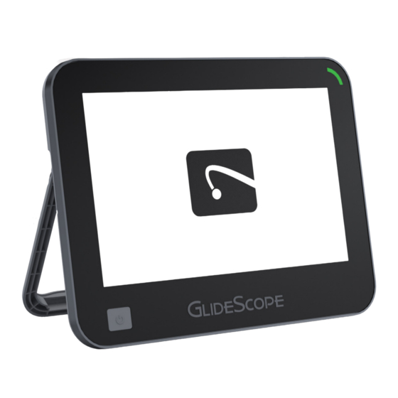
- Page 20 Figure 1. GlideScope Core Monitor Front Panel Battery indicator LED: Displays power and battery charge state LCD touch screen: Displays images from video accessories and recorded videos and Power button: images Powers the monitor on or off Figure 2. GlideScope Core Monitor Back Panel...
-
Page 21: System Features
These are not intended for patient diagnosis. For direction on using the USB pulse oximeter, please refer to the Nonin instructions for use. * GlideScope Core 15 Dual View layout pictured. Operations & Maintenance Manual: System Features 0900‑5017 REV‑07... -
Page 22: Gallery
RIGHT BAR The right bar displays an icon for connected scopes. When more than one scope is attached, the Video Layout menu is shown. For more information on video layout features, see Adjust Video Layout page 36. Buttons for Brightness Control and Contrast Control are available when they are enabled in the Settings menu. -
Page 23: Setting Up
2. Inspect the components for damage. 3. If any of the components are missing or damaged, notify the carrier and Verathon Customer Care or your local representative. For contact information, visit verathon.com/service-and-support. Operations & Maintenance Manual: Setting Up... -
Page 24: Procedure 2. Mount The System (Optional)
Mount the System (Optional) If you choose to mount the system, the GlideScope Core Premium Workstation makes it easy for you to move the system from one location to another, and to adjust the monitor’s position to fit your needs. - Page 25 ATTACH THE MONITOR TO THE WORKSTATION 1. Assemble the workstation according to its included instructions. 2. When attaching the quick-release locking plate, ensure the (4) screws are fully tightened and the locking plate is securely attached to the monitor. Note: The screws and hex driver are included with the workstation. 3.
- Page 26 ADJUST THE MONITOR TILT ANGLE TENSION If the angle of the monitor is difficult to adjust, or the monitor angle tilts down on its own, the workstation’s monitor angle tension needs to be adjusted. • Using a 4 mm hex wrench, turn the tension adjustment screw clockwise to increase the tension, or counter-clockwise to decrease it.
-
Page 27: Procedure 3. Charge The Monitor Battery
Warnings & Cautions section before performing the following task. The GlideScope Core Monitor includes an internal lithium battery. Verathon recommends that you charge the battery fully prior to first use. Under normal operating conditions, a fully charged battery lasts approximately 135 minutes for Core 10, and 90 minutes for Core 15 before it needs to be recharged. -
Page 28: Procedure 4. Complete The Setup Wizard (Optional)
Procedure 4. Complete the Setup Wizard (Optional) The first time the monitor is powered on, a setup wizard guides you through some initial settings. If the setup wizard has already been completed, or you decide to skip the setup wizard, all settings can be modified in Configure User Settings (Optional) on page 25. - Page 29 Note: When a security code is enabled, users will require it to access the Gallery and system settings. Figure 7. Security code on Figure 8. Security code off * If the security code has been forgotten, please contact Verathon Customer Care. For contact information, visit verathon.com/service-and- support. Operations & Maintenance Manual: Setting Up 0900‑5017 REV‑07...
- Page 30 5. To enable or customize an option, tap its toggle to On . The following options are available: • Brightness and Contrast: Toggle the Brightness/Contrast option. • Auto‑Shutdown options: Toggle the Auto-Shutdown feature and select the Auto-Shutdown duration. • Video Rotation: Toggle the Video Rotation menu option.
-
Page 31: Procedure 5. Configure User Settings (Optional)
Procedure 5. Configure User Settings (Optional) The Settings menu allows you to configure, change, or view the following system settings and information: Feature Settings Tab • System Sounds • Video Rotation • Video Recording • Brightness/Contrast • Dynamic Light Control •... - Page 32 Table 5. Feature Settings SETTING FUNCTION Toggles whether sound effects are heard when buttons are pressed. When on, provides options for all systems sounds, or alerts on ly. 10:55 AM CITY HOSPITAL 2017-06-05 When the System Sounds are toggled on, tap the System Sounds Video Rotation Feature...
- Page 33 REGIONAL SETTINGS TAB Use the Regional Settings tab to choose the date, date format, time, time format, daylight saving time, and time zone settings. 1. To access the Regional Settings tab, from the Home screen, tap the Main Menu button, and then tap the Settings button.
- Page 34 Displays software versions for various system resources. Reset Settings Restores all settings back to factory defaults. * If the security code has been forgotten, please contact Verathon Customer Care to request a security code reset USB flash drive. For contact information, visit verathon.com/service-and-support...
-
Page 35: Procedure 6. Attach The Video Cable And Scope
This procedure provides basic instruction on connecting compatible video cables and scopes to the monitor. For detailed information about cables and scopes, refer to one of the following manuals or contact Verathon Customer Care: •... - Page 36 The cable disconnects from the monitor. Option 1. GlideScope Core Video Cable 1. Bring into line the alignment marks on the video cable and scope connectors, and then fully insert the video cable into the scope connector port. You will hear a click when the cable is successfully connected.
-
Page 37: Procedure 7. Attach The Usb Device (Optional)
Procedure 7. Attach the USB Device (Optional) Connecting a USB drive to one of the USB ports allows you to export exams that were saved to the internal memory. The ports also allows a Nonin 3231 USB External Pulse Oximeter to be attached. The SpO reading from the sensor is shown on the Core display for convenience, but should not be used for diagnostic purposes. -
Page 38: Procedure 8. Connect To An External Monitor (Optional)
IMPORTANT To maintain electromagnetic interference (EMI) within certified limits, the system must be used with the cables, components, and accessories specified or supplied by Verathon. For additional information, see System Parts & Accessories Component Specifications sections. -
Page 39: Procedure 9. Perform A Functional Check
Perform a Functional Check Before you use the device for the first time, perform the following functional check to ensure that the system is working properly. Please contact your Verathon Customer Care representative if your system does not function as described below. -
Page 40: Using The Device
Using the Device Prior to using the device, set up the device according to the instructions in the previous chapter, and verify the setup by completing Step 1 through Step 4 of the procedure Perform a Functional Check on page 33. Please read the Warnings &... -
Page 41: Procedure 2. Use A Usb Pulse Oximeter
For direction on using the USB pulse oximeter, please refer to the Nonin instructions for use. CITY HOSPITAL The GlideScope Core monitor is compatible with the Nonin 3231 USB External Pulse Oximeter. When connected, the SpO and pulse rate can be found in the upper left corner of the display. -
Page 42: Procedure 3. Adjust Video Layout
Procedure 3. Adjust Video Layout When the monitor has two scopes connected, a video layout menu is available. This menu allows you to select how the video feeds are displayed. Attached scopes Video layout menu (updates to match the current layout) 1. -
Page 43: Procedure 4. Rotate The Display
Procedure 4. Rotate the Display The display can be rotated 180 degrees if needed. The option to show the video rotation button can be turned on or off in the user settings. To change this setting, see Configure User Settings (Optional) on page 25. -
Page 44: Procedure 6. Use The Gallery
2. When you are finished recording, press the Record button again. The recording stops. 3. If you would like to save a photo of the live display, press the Snapshot button. A frame briefly appears around the video to indicate the snapshot has been taken. This can also be done while the recording video. - Page 45 2. To select all the files in a row, tap the Select All check box to the left of the row. 2018-05-22 10:29 2018-05-22 10:29 6:13 6:13 2018-06-01 8:10 2018-06-01 8:10 FAVORITES 0:48 0:48 1. To mark a file as a favorite, tap the check box to select the file(s), and then tap the Favorite button in the left bar.
- Page 46 2. Connect the USB flash drive to the one of the USB ports. USB ports 3. Ensure that the USB flash drive is detected by verifying the USB icon is visible at the top of the screen. 4. From the Home screen, tap the Main Menu button, and then tap the Gallery button.
- Page 47 Viewing Media If you would like to export, delete, or favorite a file being viewed, tap the check box at the upper left corner of the file thumbnail, and then tap the corresponding button on the left of the display. 10:55 CITY HOSPITAL 2018-10-14...
- Page 48 VIEW A SNAPSHOT • To review a recorded snapshot, tap its thumbnail. The Photo Viewer opens. 10:55 AM CITY HOSPITAL 2017-06-05 95 min 2016-01-06 6:16 AM Internal Storage USB Drive 0:27 2017-03-15 1:44 PM 2017-05-22 10:29 AM VIEW PATIENT NOTES 1.
-
Page 49: Reprocessing
For information about the cleaning, disinfection, and sterilization requirements for these components, refer to the GlideScope and GlideRite Products Reprocessing Manual, which is available at verathon.com/service-and-support/glidescope-reprocessing-products. Operations & Maintenance Manual: Reprocessing 0900‑5017 REV‑07... -
Page 50: Maintenance & Safety
The battery is not user-replaceable. In case of battery malfunction, do not attempt to replace the monitor battery. Any attempts to replace the battery by unauthorized service technicians may cause serious harm to the user and will void the warranty. Please contact your Verathon Customer Care representative for more information on battery replacement. -
Page 51: Device Repair
Device Repair The GlideScope Core components are not user-serviceable. Verathon does not make available any type of circuit diagrams, component parts lists, descriptions, or other information that would be required for repairing the device and related accessories. All service must be performed by a qualified technician. -
Page 52: Limited Warranty
Warranty is void. If a Product purchased by Customer requires Service, Verathon will, at its discretion, either repair or replace the Product and may provide a loaner unit, at Customer’s request. Customer shall send the defective Product to Verathon (cleaned and disinfected as appropriate). - Page 53 Verathon shall be free from defect in materials and workmanship for the Term. Customer shall notify Verathon if and to what respect any of said guarantees have not been met and Verathon shall promptly, at its own expense and sole discretion, re-perform such services and make such alteration, repair, or replacement as may be necessary to meet the guarantees hereunder so long as the non-performance is due to a manufacturer defect and not physical or Customer induced issues after the service is completed.
-
Page 54: Product Specifications
Product Specifications Component Specifications Video Monitor Specifications Table 8. Core 10 (0570‑0376) GENERAL SPECIFICATIONS Classification: Electrical Class II, Applied Part BF Range: 100–240 V AC, 50 and 60 Hz Line voltage: (If the power cord has a third prong, the third conductor is not intended to be a protective earth connection for the medical power supply.) DC power supply: 12 V DC, 2.5 A max... - Page 55 Table 9. Core 10 FHD (0570‑0436) GENERAL SPECIFICATIONS Classification: Electrical Class II, Applied Part BF Range: 100–240 V AC, 50 and 60 Hz Line voltage: (If the power cord has a third prong, the third conductor is not intended to be a protective earth connection for the medical power supply.) DC power supply: 12 V DC, 2.5 A max...
- Page 56 Table 10. Core 15 (0570‑0404) GENERAL SPECIFICATIONS Classification: Electrical Class II, Applied Part BF Range: 100–240 V AC, 50 and 60 Hz Line voltage: (If the power cord has a third prong, the third conductor is not intended to be a protective earth connection for the medical power supply.) DC power supply: 12 V DC, 2.5 A max...
- Page 57 Table 11. Core 15 FHD (0570‑0437) GENERAL SPECIFICATIONS Classification: Electrical Class II, Applied Part BF Range: 100–240 V AC, 50 and 60 Hz Line voltage: (If the power cord has a third prong, the third conductor is not intended to be a protective earth connection for the medical power supply.) DC power supply: 12 V DC, 2.5 A max...
- Page 58 Workstations Table 12. Premium Workstation (0800‑0636) COMPONENT SPECIFICATIONS Wheelbase diameter (A) 64 cm Min. height (B) 142 cm ± 2 cm B–C Max. height (C) 165 cm ± 2 cm Safe working load 42 kg Table 13. Premium Workstation (0800‑0557) COMPONENT SPECIFICATIONS Wheelbase diameter (A) 64 cm...
- Page 59 Electromagnetic Compatibility The system is designed to be in compliance with IEC 60601-1-2, which contains electromagnetic compatibility (EMC) requirements for medical electrical equipment. The limits for emissions and immunity specified in this standard are designed to provide reasonable protection against harmful interference in a typical medical installation.
- Page 60 Table 15. Guidance and Manufacturer’s Declaration —Electromagnetic Immunity The system is intended for use in the electromagnetic environment specified below. The customer or the user of the system should ensure that it is used in such an environment. COMPLIANCE ELECTROMAGNETIC IMMUNITY TESTS IEC 60601 TEST LEVEL LEVEL...
- Page 61 Table 15. Guidance and Manufacturer’s Declaration —Electromagnetic Immunity The system is intended for use in the electromagnetic environment specified below. The customer or the user of the system should ensure that it is used in such an environment. COMPLIANCE ELECTROMAGNETIC IMMUNITY TESTS IEC 60601 TEST LEVEL LEVEL...
- Page 62 Accessory Conformance to Standards To maintain electromagnetic interference (EMI) within certified limits, the system must be used with the cables, components, and accessories specified or supplied by Verathon. For additional information, see System Parts & Accessories Component Specifications sections.
-
Page 63: Glossary
The following table provides definitions for specialized terms used in this manual or on the product itself. For a full list of caution, warning, and informational symbols used on this and other Verathon products, please refer to the Verathon Symbol Glossary at verathon.com/service-and-support/symbols. - Page 64 TERM DEFINITION Relative humidity Restriction of the Use of Certain Hazardous Substances in Electrical and RoHS Electronic Equipment Volt Vrms Voltage root mean squared Watt WEEE Waste electrical and electronic equipment GlideScope Core ® 0900‑5017 REV‑07...
Need help?
Do you have a question about the GlideScope Core and is the answer not in the manual?
Questions and answers